
Related Manuals for EWM Pico 160 cel puls


Summary of Contents for EWM Pico 160 cel puls
- Page 1 Operating instructions Welding machine Pico 160 cel puls Pico 160 cel puls VRD (RU) Pico 160 cel puls VRD (AUS) 099-002129-EW501 Observe additional system documents! 15.10.2020...
- Page 2 +49 2680 181-0. A list of authorised sales partners can be found at www.ewm-group.com/en/specialist-dealers. Liability relating to the operation of this equipment is restricted solely to the function of the equipment. No other form of liability, regardless of type, shall be accepted.
-
Page 3: Table Of Contents
Contents Notes on using these operating instructions Contents 1 Contents ............................3 2 For your safety ..........................5 Notes on using these operating instructions ................5 2.1.1 Explanation of icons ....................5 2.1.2 Complete documentation ..................6 General ..........................6 3 Intended use ........................... - Page 4 Dynamic power adjustment ....................36 Resetting welding parameters to the factory settings ............37 8 Technical data..........................38 Pico 160 cel puls ........................38 9 Accessories ..........................39 Electrode holder / workpiece lead ..................39 Remote controls and accessories ..................39 TIG welding torch .........................
-
Page 5: For Your Safety
For your safety Notes on using these operating instructions For your safety Notes on using these operating instructions 2.1.1 Explanation of icons Symbol Description Symbol Description Indicates technical aspects which the u- Activate and release / Tap / Tip ser must observe. Switch off machine Release Switch on machine... -
Page 6: Complete Documentation
For your safety General 2.1.2 Complete documentation These operating instructions are part of the complete documentation and valid only in combination with the "Safety instructions”! Read and observe the documents for all system components! Figure 2-1 Item Documentation Safety instructions Power source Electrode holder/welding torch Remote control... - Page 7 For your safety General Requirements for connection to the public mains network High-performance machines can influence the mains quality by taking current from the mains network. For some types of machines, connection restrictions or requirements relating to the maximum possible line impedance or the necessary minimum supply capacity at the interface with the public network (Point of Common Coupling, PCC) can therefore apply.
-
Page 8: Intended Use
3.2.1 Warranty For more information refer to the "Warranty registration" brochure supplied and our information regarding warranty, maintenance and testing at www.ewm-group.com! 3.2.2 Declaration of Conformity This product corresponds in its design and construction to the EU directives listed in the decla- ration. -
Page 9: Machine Description - Quick Overview
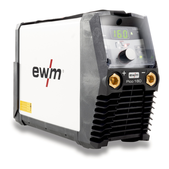
Machine description – quick overview Front view Machine description – quick overview Front view Figure 4-1 Item Symbol Description Carrying strap > see 5.1.4.1 chapter Machine control > see 4.3 chapter Protective cap Connection socket, "+" welding current • MMA: Electrode holder or workpiece lead connection •... -
Page 10: Rear View
Machine description – quick overview Rear view Rear view Figure 4-2 Item Symbol Description Main Switch Switching the machine on or off. Cooling air inlet Mains connection cable > see 5.1.7 chapter 099-002129-EW501 15.10.2020... -
Page 11: Machine Control - Operating Elements
Machine description – quick overview Machine control – Operating elements Machine control – Operating elements Figure 4-3 Item Symbol Description Excess temperature signal light In case of excess temperature, temperature monitors de-activate the power unit, and the excess temperature control lamp comes on. Once the machine has cooled down, welding can continue without any further measures. -
Page 12: Design And Function
Design and function Transport and installation Design and function WARNING Risk of injury from electrical voltage! Contact with live parts, e.g. power connections, can be fatal! • Observe the safety information on the first pages of the operating instructions! • Commissioning must be carried out by persons who are specifically trained in handling power sources! •... -
Page 13: Ambient Conditions
Design and function Transport and installation 5.1.3 Ambient conditions T he machine must not be operated in the open air and must only be set up and operated on a suitable, stable and level base! • The operator must ensure that the ground is non-slip and level, and provide sufficient lighting for the place of work. -
Page 14: Notes On The Installation Of Welding Current Leads
Design and function Transport and installation 5.1.5 Notes on the installation of welding current leads • Use an individual welding lead to the workpiece for each welding machine! Figure 5-2 • Fully unroll welding current leads, torch hose packages and intermediate hose packages. Avoid loops! •... -
Page 15: Stray Welding Currents
Design and function Transport and installation 5.1.6 Stray welding currents WARNING Risk of injury due to stray welding currents! Stray welding currents can destroy protective earth conductors, damage machines and electronic devices and cause overheating of components, leading to fire. •... -
Page 16: Mains Connection
Design and function Operating the machine control 5.1.7 Mains connection DANGER Hazards caused by improper mains connection! An improper mains connection can cause injuries or damage property! • The connection (mains plug or cable), the repair or voltage adjustment of the device must be carried out by a qualified electrician in accordance with the respective local laws or nati- onal regulations! •... -
Page 17: Mma Welding
Design and function MMA welding MMA welding 5.4.1 Connecting the electrode holder and workpiece lead CAUTION Risk of crushing and burns! When changing stick electrodes there is a risk of crushing and burns! • Wear appropriate and dry protective gloves. •... -
Page 18: Welding Task Selection
Design and function MMA welding 5.4.2 Welding task selection Figure 5-7 Type Electrode type Rutile Rutile-basic Basic Rutile cellulose Cellulose 5.4.3 Arcforce During the welding process, arcforce prevents the electrode sticking in the weld pool with increases in current. This makes it easier to weld large-drop melting electrode types at low current strengths with a short arc in particular. -
Page 19: Antistick
Design and function MMA welding 5.4.5 Antistick The Antistick feature prevents the electrode from annealing. Should the electrode stick despite the Arcforce feature, the machine au- tomatically switches to the minimum current within approx. one second. This prevents the electrode from annealing. Check the welding current setting and correct for the welding task in hand. -
Page 20: Expert Menu (Mma)
Design and function MMA welding 5.4.7 Expert menu (MMA) The Expert menu has adjustable parameters stored that don’t require regular setting. The number of pa- rameters shown may be limited, e.g. if a function is deactivated. The setting ranges for the parameter values are summarised in the Parameter overview sec- tion >... -
Page 21: Tig Welding
Design and function TIG welding TIG welding 5.5.1 Connecting a TIG welding torch with rotating gas valve Prepare welding torch according to the welding task in hand (see operating instructions for the torch). Figure 5-14 Item Symbol Description Workpiece Connection socket for "+" welding current Workpiece lead connection Output side of the pressure regulator Welding torch... -
Page 22: Pressure Regulator Connection
Design and function TIG welding 5.5.3 Pressure regulator connection Figure 5-15 Item Symbol Description Pressure regulator Output side of the pressure regulator Shielding gas cylinder Cylinder valve • Before connecting the pressure regulator to the gas cylinder, open the cylinder valve briefly to blow out any dirt. -
Page 23: Arc Ignition
Design and function TIG welding 5.5.6 Arc ignition 5.5.6.1 Liftarc Figure 5-17 The arc ignites through contact with the workpiece: a) Carefully place the torch gas nozzle and tungsten electrode tip against the workpiece (lift arc current flows independent of the set main current) b) Angle the torch above the torch gas nozzle until the distance between electrode tip and workpiece is approx. -
Page 24: Expert Menu (Tig)
Design and function TIG welding 5.5.8 Expert menu (TIG) The Expert menu has adjustable parameters stored that don’t require regular setting. The number of pa- rameters shown may be limited, e.g. if a function is deactivated. The setting ranges for the parameter values are summarised in the Parameter overview sec- tion >... -
Page 25: Degaussing
Design and function Degaussing Degaussing CAUTION Movement forces due to electromagnetic fields! Electromagnetic fields may exert movement forces on unsecured metal objects! This may result in injury for example by tools that are set in motion uncontrolled, etc. • Remove metal objects lying around from the working area or secure against movement. 5.6.1 Description of procedure With the process activgauss, an adjustable direct current is used to generate an opposing magnetic field. -
Page 26: Generating An Opposing Magnetic Field During Welding (Activgauss)
Design and function Degaussing Large or long workpieces Figure 5-22 • Lay power cables tightly around the component. • Lay power cables up to the welding-relevant area, such as the sidewall of the joint. If the space required by the power lines is too large, the turns can also be placed on top of each other. - Page 27 Design and function Degaussing The process must be activated before use. The subsequent restarting of the power source switches back to the last active welding procedure. Figure 5-25 Display Setting/selection Degaussing is activated. Figure 5-26 • Press the welding procedure/ degaussing pushbutton. •...
-
Page 28: Automatic Cut-Out
Design and function Remote control Figure 5-27 • Measure the magnetic flux density. • Compare the measured magnetic flux density with the table “Guide values for residual flux den- sity” > see 11.2 chapter for the corresponding welding process. If the residual field strength is too high, the process of degaussing can be repeated as often as desired (increase the number of turns if necessary). -
Page 29: Power-Saving Mode (Standby)
Design and function Power-saving mode (Standby) Power-saving mode (Standby) You can activate the power-saving mode by either pressing the push-button > see 4.3 chapter for a pro- longed time or by setting a parameter in the machine configuration menu (time-controlled power-saving mode ) >... -
Page 30: Machine Configuration Menu
Design and function Machine configuration menu 5.12 Machine configuration menu Basic machine settings are defined in the machine configuration menu. Figure 5-29 Display Setting/selection Calibration The machine will be calibrated for approx 2 seconds each time it is switched on. Exit the menu Exit Machine configuration... - Page 31 Design and function Machine configuration menu Display Setting/selection Service menu Any changes to the service menu should be agreed with the authorised service person- nel. Software version of the machine control Version display 099-002129-EW501 15.10.2020...
-
Page 32: Maintenance, Care And Disposal
Maintenance, care and disposal General Maintenance, care and disposal General DANGER Risk of injury due to electrical voltage after switching off! Working on an open machine can lead to fatal injuries! Capacitors are loaded with electrical voltage during operation. Voltage remains present for up to four minutes after the mains plug is removed. -
Page 33: Maintenance Work, Intervals
A periodic test according to IEC 60974-4 "Periodic inspection and test" has to be carried out. In addition to the regulations on testing given here, the relevant local laws and regulations must also be observed. For more information refer to the "Warranty registration" brochure supplied and our information regarding warranty, maintenance and testing at www.ewm-group.com! 099-002129-EW501 15.10.2020... -
Page 34: Disposing Of Equipment
• Information about returning used equipment or about collections can be obtained from the respective municipal administration office. • In addition to this, returns are also possible throughout Europe via EWM sales partners. 099-002129-EW501 15.10.2020... -
Page 35: Rectifying Faults
Rectifying faults Error messages (power source) Rectifying faults All products are subject to rigorous production checks and final checks. If, despite this, something fails to work at any time, please check the product using the following flowchart. If none of the fault rectification procedures described leads to the correct functioning of the product, please inform your authorised dea- ler. -
Page 36: Checklist For Rectifying Faults
Rectifying faults Checklist for rectifying faults Error message Possible cause Remedy Earth fault (PE error) Connection between welding wire and machine casing Failure of a mains phase Switch off the machine and check the mains vol- tage Short circuit in welding circuit Switch off the machine and check welding current leads for correct installation, e.g. -
Page 37: Resetting Welding Parameters To The Factory Settings
Rectifying faults Resetting welding parameters to the factory settings Resetting welding parameters to the factory settings All customised welding parameters that are stored will be replaced by the factory settings. RESET Figure 7-1 Display Setting/selection Calibration The machine will be calibrated for approx 2 seconds each time it is switched on. Initialising Keep the push-button pressed until is shown on the display. -
Page 38: Technical Data
Technical data Pico 160 cel puls Technical data Performance specifications and guarantee only in connection with original spare and replacement parts! Pico 160 cel puls Welding current (I 5 A to 150 A 5 A to 160 A Welding voltage according to standard (U... -
Page 39: Accessories
Accessories Electrode holder / workpiece lead Accessories Electrode holder / workpiece lead Type Designation Item no. EH25 QMM 4M Electrode holder 094-005800-00000 WK16mm² 170A/60% 4m/K Workpiece lead 094-005801-00000 Remote controls and accessories Type Designation Item no. RG13 Remote control 090-008113-00000 TIG welding torch Type Designation... -
Page 40: Service Documents
Service documents Spare and replacement parts Service documents WARNING Do not carry out any unauthorised repairs or modifications! To avoid injury and equipment damage, the unit must only be repaired or modified by specialist, skilled persons! The warranty becomes null and void in the event of unauthorised interference. •... - Page 41 Service documents Spare and replacement parts Item Order number Name Type 094-015236-E0501 Carrying strap TG3-E 094-021818-E0501 Casing panel BH276,5X201,5X124,2 094-021826-00000 Insulating foil 040-001090-E0000 Operating panel assembly with E160 rotary transducer 044-004185-10015 Rotary transducer 30POS/1,5NCM 094-019308-00000 Plastic insulation for rotary trans- KID/D23X7,3 ducer 094-021994-00000 Fibre optics...
-
Page 42: Circuit Diagram
Service documents Circuit diagram 10.2 Circuit diagram Figure 10-2 099-002129-EW501 15.10.2020... -
Page 43: Appendix
Appendix Parameter overview – setting ranges Appendix 11.1 Parameter overview – setting ranges Parameters/function Setting range MMA (MMA) Main current (AMP) Hot start current (AMP%) Hot start time (sec) 20,0 Arcforce correction Pulse frequency Pulse balance Pulse current Arc length restriction TIG (TIG) Main current AMP Ignition current... -
Page 44: Guide Values Of Magnetic Flux Density, Weldability
Appendix Guide values of magnetic flux density, weldability 11.2 Guide values of magnetic flux density, weldability TIG welding GMAW welding Magnetic flux density Weldability Magnetic flux density Weldability <0.5 mT very good <3 mT very good 0.5-1 mT good 3-4 mT good 1-2 mT possible... -
Page 45: Searching For A Dealer
Appendix Searching for a dealer 11.3 Searching for a dealer Sales & service partners www.ewm-group.com/en/specialist-dealers "More than 400 EWM sales partners worldwide" 099-002129-EW501 15.10.2020...
Need help?
Do you have a question about the Pico 160 cel puls and is the answer not in the manual?
Questions and answers