Table of Contents
Advertisement
Quick Links
Advertisement
Table of Contents

Related Manuals for HT HT9012


Summary of Contents for HT HT9012
- Page 1 ENGLISH User manual Copyright HT ITALIA 2013 Versione EN 2.00 - 25/03/2013...
- Page 2 HT9012 Contents: SAFETY PRECAUTIONS AND PROCEDURES ............2 Preliminary ........................2 Before use ........................3 After use .......................... 3 Measuring (overvoltage) categories definitions ..............3 GENERAL DESCRIPTION ................... 4 TRMS and Mean Value measuring instruments ............... 4 True Root Mean Square value and crest factor definitions ..........4 PREPARATION FOR USE ...................
-
Page 3: Safety Precautions And Procedures
HT9012 1 SAFETY PRECAUTIONS AND PROCEDURES This clamp complies with IEC/EN61010-1. For your own safety and in order to avoid damaging the instrument, you’re recommended to keep to the instructions contained in this manual and read carefully all the notes preceded by the symbol... -
Page 4: Before Use
HT9012 1.2 BEFORE USE Always keep to the instructions contained in this manual: CAUTION Non compliance with the warnings and/or the instructions may damage the tester and/or its components or injure the operator. Before changing the switch’s position, take off the clamp jaw from the tested conductor... -
Page 5: General Description
HT9012 2 GENERAL DESCRIPTION HT9012 meter can performs the herewith measurements: DC and AC voltage Detection of AC voltage without contact AC current Resistance and test continuity Diode test Each parameter can be selected by rotating the 8-positions switch included OFF position. -
Page 6: Preparation For Use
HT9012 3 PREPARATION FOR USE 3.1 INITIAL The tester has been checked from a mechanical and electrical point of view before shipment. Every care has been taken to make sure that the instrument reaches you in perfect conditions. However, it’s advisable to make a rapid check in order to detect eventual damages which may have occurred in transit. -
Page 7: Operating Instructions
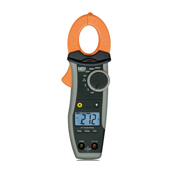
HT9012 4 OPERATING INSTRUCTIONS 4.1 INSTRUMENT DESCRIPTION 4.1.1 Commands description LEGEND: 1. Clamp jaw 2. Red LED for AC voltage detection without contact 3. Clamp trigger 4. Rotary function selector 5. HOLD key backlight key 7. LCD display 8. MODE key 9. -
Page 8: Function Key Description
HT9012 4.2 FUNCTION KEY DESCRIPTION 4.2.1 HOLD key By pushing HOLD key the parameter’s measured value is frozen on the display and the symbol “HOLD” appears on it. Pushing HOLD key another time deactivates this mode. 4.2.2 key for about 1s it’s possible to activate the backlight function on By pushing and hold the display. -
Page 9: Functions Of Rotary Switch Description
HT9012 4.3 FUNCTIONS OF ROTARY SWITCH DESCRIPTION 4.3.1 DC Voltage measurement CAUTION Maximum input Voltage measurements 1000VDC 1000VACrms. Do not take any voltage measurement exceeding this limit in order not to risk electrical shock or damaging the meter. Fig. 3: Taking DC voltage measurement position. -
Page 10: Ac Voltage Measurement
HT9012 4.3.2 AC Voltage measurement CAUTION Maximum input Voltage measurements 1000VDC 1000VACrms. Do not take any voltage measurement exceeding this limit in order not to risk electrical shock or damaging the meter. Fig. 4: Taking AC voltage measurement 1. Approach the meter closest to AC source and note the turn on of red LED which is placed to the bottom of clamp jaws (see Fig. -
Page 11: Ac Current Measurement
HT9012 4.3.3 AC Current measurement CAUTION Make sure that all the test leads are disconnected from the meter terminals for current measurement. Fig. 5: Taking AC current measurement 1. Approach the meter closest to AC source. The turn on of red LED which is placed to the bottom of clamp jaws (see Fig. -
Page 12: Resistance Measurement
HT9012 4.3.4 Resistance measurement CAUTION Before taking any in circuit resistance measurement, remove power from the circuit to be tested and discharge all the capacitors. Fig. 6: Taking resistance measurement position. The “ ” symbol is shown at display 1. Rotate the switch on 2. -
Page 13: Continuity Test And Diode Test
HT9012 4.3.5 Continuity test and Diode test CAUTION Before taking any in circuit resistance measurement or diode test, remove power from the circuit to be tested and discharge all the capacitors. Fig. 7: Taking continuity test and diode test 1. Rotate the switch on position 2. -
Page 14: Maintenance
HT9012 5 MAINTENANCE 5.1 GENERAL INFORMATIONS 1. This digital clamp meter is a precision instrument. Whether in use or in storage, please do not exceed the specification requirements to avoid possible damages or dangers 2. Do not place this meter at high temperatures or humidity or expose it to direct sunlight 3. -
Page 15: Technical Specifications
HT9012 6 TECHNICAL SPECIFICATIONS 6.1 CHARACTERISTICS Accuracy is calculated as [% rdg + (n°of dgt) * resolution] referred to: 23°C ± 5°C <80%RH DC Voltage Input Overload Range Resolution Accuracy impedance protection 200.0mV 0.1mV 2.000V 0.001V 20.00V 0.01V (1.0%rdg + 3dgt) 1000VDC/ACrms 200.0V... -
Page 16: Safety
This product conforms to the prescriptions of the European directive on low voltage 2006/95/EEC and to EMC directive 2004/108/EEC 6.3 ACCESSORIES 6.3.1 Standard accessories The content of a standard package is the following: Instrument HT9012 Test leads - Cod. 4413-2 Carrying bag Battery User manual... -
Page 17: Service
HT9012 7 SERVICE 7.1 WARRANTY CONDITIONS This instrument is guaranteed against material or production defects, in accordance with our general sales conditions. During the warranty period the manufacturer reserves the right to decide either to repair or replace the product.
Need help?
Do you have a question about the HT9012 and is the answer not in the manual?
Questions and answers