
Related Manuals for Omega TX93A


Summary of Contents for Omega TX93A
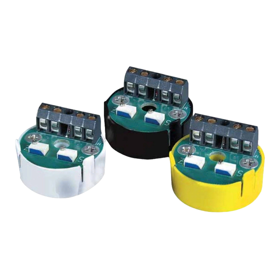
- Page 1 User’s Gui d e Shop online at omega.com e-mail: info@omega.com For latest product manuals: www.omegamanual.info TX93A (J, K, T, E) 4-20 mA Ultra-Miniature Temperature Transmitters...
- Page 2 Fax: (203) 359-7700 e-mail: info@omega.com For Other Locations Visit omega.com/worldwide The information contained in this document is believed to be correct, but OMEGA accepts no liability for any errors it contains, and reserves the right to alter specifications without notice.
-
Page 3: Table Of Contents
TABLE OF CONTENTS Section 1 Getting Started 1.1 Unpacking ........1 1.2 Safety and EMC Considerations . - Page 4 FIGURES & TABLES Figure 1-1 Thermocouple Transmitter ......2 Figure 1-2 Straight Line Approximation of a Curve ....3 Figure 2-1 Assembly inside an NB2 Protection Head .
-
Page 5: Unpacking
1.1 Unpacking Remove the packing list and verify that you have received all equipment. If you have any questions, contact the nearest Customer Service Department, as listed on the cover of this manual. Upon receipt of shipment, inspect the container and equipment for any signs of damage. - Page 6 1.3 General Description (continued) The transmitter is normally powered by an unregulated power supply as shown in Figure 1-1. The proportionally-transmitted signal begins at 4mA, at the low end of its temperature range, and increases to 20mA, at the high end of its temperature range. (There are various temperature ranges/ thermocouple types available for the transmitter.
-
Page 7: Features
1.3 General Description (continued) Most thermocouple transmitters with 4-20 mA outputs, including this transmitter , are proportional with respect to the thermocouple input voltage. However, the relationship between temperature and millivolt for all the thermocouple types is somewhat non-linear. This leads to maximum error at approximately the midpoint of the range as shown in Figure 1-2. -
Page 8: Models Available
0 to 750 F (-18 to 399 C) 0 to 1000 F (-18 to 538 C) Table 1-2 Model Numbers Model Number Description TX93A-(*) Thermocouple Transmitter (J, K, T, or E) NB2TX93A-(*) NB2 thermocouple probe, 12"L, 1/4” O.D., ungrounded junction, 304SS sheath... -
Page 9: Mounting
2.1 Mounting The transmitter may be: 1. surface mounted 2. mounted inside a protection head (shown in Figure 2-1) POWER LINES T/C WIRES SECTION A-A Figure 2-1 Assembly of the Transmitter inside an NB2 Protection Head... -
Page 10: Wiring
2.2 Wiring Refer to Figure 2-2 Connect a dc power supply in series with the load to the (+PS) and (-PS) power terminals. Note that the load (usually a monitoring instrument) may be connected to either the (+) or (-) power lead. Connect the thermocouple to the (+IN) and (-IN) input terminals. -
Page 11: Equipment Required
• Precision DVM with ±0.002 mV accuracy and an adjustable mV source with 0.001 mV resolution • OMEGA TRC III Ice Point Reference (or stable ice bath) • Temperature Reference Probe Part Number: TRP-(*) *Thermocouple Type J, K, T, E 3.2 Set-Up of Equipment... -
Page 12: Calibration Procedures
Select, from Table 3-1, the correct mV input values for the Z (zero) and S (span) adjustments that correspond to the model number. For example, for Model TX93A-J2, the Z input is -0.886 mV, and the S input is 4.907 mV. - Page 13 3.3 Calibration Procedures (continued) Figure 3-1 Transmitter Calibration Set-Up Figure 3-2 Transmitter Calibration Set- Up (Alternate)
-
Page 14: Troubleshooting Guide
Table 3-1. Calibration Values Temperature mV Input mV Input Input Range Model Ref 32°F Model Ref 32°F Zero/Span TX93A Zero/Span TX93A Zero/Span -40/120°F -1.961/2.527 0/200°F -0.886/4.907 -0.692/3.820 0/300°F -0.886/7.949 -0.692/6.094 0/500°F -0.886/14.110 -0.692/10.561 0/750°F -0.886/21.787 -0.692/16.350 0/1000°F -0.886/29.521 -0.692/22.255 -40/120°F –... -
Page 15: Specifications
4.1 Troubleshooting Guide (continued) Loose or broken wires: Check each terminal connection for tightness. Move each wire back and forth and note any changes in operation. Too high a load resistance in the output current loop or too low a current rating on the power supply: Measure the total resistance of each device (excluding the transmitter and power supply) in the 20 mA loop, including... - Page 16 5.1 Specifications (continued) Zero/Span Adj Range: ±25% Power Supply Voltage Operating Range: +8 Vdc to +35 Vdc, 28 mA max required per transmitter Accuracy: ±0.1% of full scale (includes effects of hysteresis, repeatability and linearity proportional to the T/C) Frequency Response: 3dB@ 3Hz Thermal Zero Shift: <0.01%/°F of span (span >10 mV)
- Page 17 Notes: ________________________________________ ________________________________________ ________________________________________ ________________________________________ ________________________________________ ________________________________________ ________________________________________ ________________________________________ ________________________________________ ________________________________________ ________________________________________ ________________________________________ ________________________________________ ________________________________________ ________________________________________ ________________________________________ ________________________________________ ________________________________________ ________________________________________ ________________________________________ ________________________________________ ________________________________________ ________________________________________...
- Page 18 Notes: ________________________________________ ________________________________________ ________________________________________ ________________________________________ ________________________________________ ________________________________________ ________________________________________ ________________________________________ ________________________________________ ________________________________________ ________________________________________ ________________________________________ ________________________________________ ________________________________________ ________________________________________ ________________________________________ ________________________________________ ________________________________________ ________________________________________ ________________________________________ ________________________________________ ________________________________________ ________________________________________...
- Page 19 Department will issue an Authorized Return (AR) number immediately upon phone or written request. Upon examination by OMEGA, if the unit is found to be defective, it will be repaired or replaced at no charge. OMEGA’s WARRANTY does not apply to defects resulting from any action of the purchaser, including but not limited to mishandling, improper interfacing, operation outside of design limits, improper repair, or unauthorized modification.
- Page 20 Where Do I Find Everything I Need for Process Measurement and Control? OMEGA…Of Course! Shop online at omega.com TEMPERATURE M U Thermocouple, RTD & Thermistor Probes, Connectors, Panels & Assemblies M U Wire: Thermocouple, RTD & Thermistor M U Calibrators & Ice Point References M U Recorders, Controllers &...
Need help?
Do you have a question about the TX93A and is the answer not in the manual?
Questions and answers