
Related Manuals for Omega TX92A


Summary of Contents for Omega TX92A
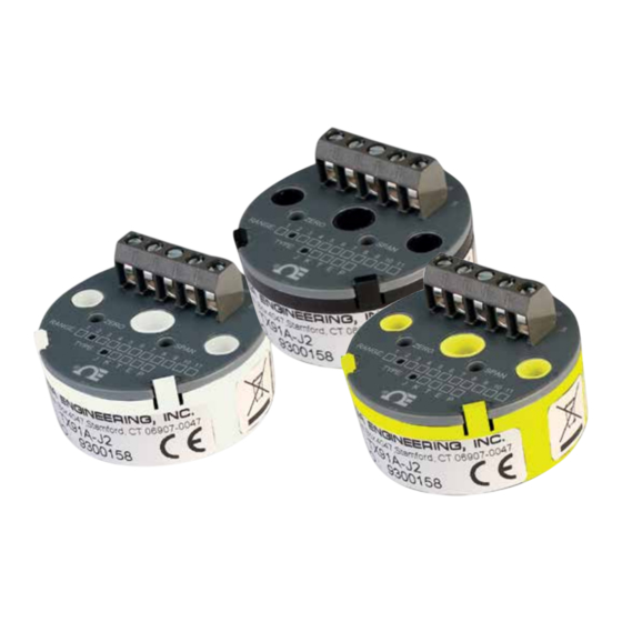
- Page 1 User’s Gui d e Shop online at omega.com e-mail: info@omega.com For latest product manuals: www.omegamanual.info TX92A Miniature Temperature Transmitters...
- Page 2 Fax: (203) 359-7700 e-mail: info@omega.com For Other Locations Visit omega.com/worldwide The information contained in this document is believed to be correct, but OMEGA accepts no liability for any errors it contains, and reserves the right to alter specifications without notice.
-
Page 3: Table Of Contents
T T A A B B L L E E O O F F C C O O N N T T E E N N T T S S P P A A G G E E GETTING STARTED Unpacking . -
Page 5: Unpacking
8-to-50 Vdc source to produce the 4-to-20 mA output signal. As much as 800 ohms dropping resistance may be used in the power leads of the TX92A when the unit is energized from a 24 Vdc source because of the small compliance voltage needed by the unit. -
Page 6: Available Ranges
4-mA output temperature within +/- 25% for Fahrenheit and +/- 10% for Celsius of nominal span (refer to Section 3.0, Calibrating the Transmitter, for more details). Models TX92A-*-L are transmitters with the 4-20mA output linearized to temperature. -
Page 7: Ordering Guide
4-20mA output linearized to temperature **Factory Scaling Option: **Factory Scaling available for additional charge. Consult factory. To order additional transmitters, specify TX92A followed by the model number. For example: TX92A-2 = RTD Transmitter with a temperature range of -0 to 200°F. -
Page 8: Connecting Power And Signal Inputs
2.0 CONNECTING POWER AND SIGNAL INPUTS Verify that the transmitter is connected for the correct power voltage rating. Connect the power supply to pin 4 and the resistance load to pin 5. Connect the sensor to pins 1, 2 and 3. The transmitter has no power on switch, so it will be in operation as soon as you apply power. -
Page 9: Calibrating The Transmitter
CALIBRATING THE TRANSMITTER Calibration Setup: Insert the reference RTD. Connect RTD simulator. Connect DMM monitor and power supply. (4–20 mA) SPAN MONITOR (–) DC SUPPLY 24 VDC 250 Ohms (–) RESISTANCE SOURCE (–) INPUT ZERO WIRE COPPER WIRE Figure 3-1. Calibration Setup (Resistance Source) To calibrate the transmitter, follow these steps (refer to Figure 3-1): Locate the model number in Table 3-1 or 3-2 and set the resistance source to the LO-IN value. - Page 10 CALIBRATING THE TRANSMITTER (Continued) An RTD calibrator may be used in place of the resistance source - refer to Figure 3-2. (4–20 mA) SPAN MONITOR (–) DC SUPPLY 24 VDC 250 Ohms (–) CALIBRATOR INPUT ZERO WIRE Figure 3-2. Calibration Setup (RTD Simulator) Table 3-1.
-
Page 11: Specifications
4.0 SPECIFICATIONS I I N N P P U U T T Configuration: Non-isolated input Transducer types: Platinum RTD Burnout indication: Upscale over-range indication, 40 mA max. O O U U T T P P U U T T Linear range: 4 to 20 mAdc Current Output limits: <2 to >40 mA (open RTD) - Page 12 4.0 SPECIFICATIONS (Continued) 2 3 4 5 1.750 [44.45] DIA. .650 .650 [1.650] [1.650] 1 2 3 4 5 1.150 [29.21] .750 [19.05] Figure 4-1. Case Dimensions > 4 REGULATOR < < –V CURRENT > 5 CONTROL Figure 4-2. Transmitter Block Diagram...
- Page 13 - NOTES -...
- Page 14 - NOTES -...
- Page 15 Department will issue an Authorized Return (AR) number immediately upon phone or written request. Upon examination by OMEGA, if the unit is found to be defective, it will be repaired or replaced at no charge. OMEGA’s WARRANTY does not apply to defects resulting from any action of the purchaser, including but not limited to mishandling, improper interfacing, operation outside of design limits, improper repair, or unauthorized modification.
- Page 16 Where Do I Find Everything I Need for Process Measurement and Control? OMEGA…Of Course! Shop online at omega.com TEMPERATURE M U Thermocouple, RTD & Thermistor Probes, Connectors, Panels & Assemblies M U Wire: Thermocouple, RTD & Thermistor M U Calibrators & Ice Point References M U Recorders, Controllers &...
Need help?
Do you have a question about the TX92A and is the answer not in the manual?
Questions and answers