Advertisement
Quick Links
User' s Guide
UK
UK
UK
UK
UK
UK
Shop online at
omega.com
e-mail: info@omega.com
For latest product manuals:
omegamanual.info
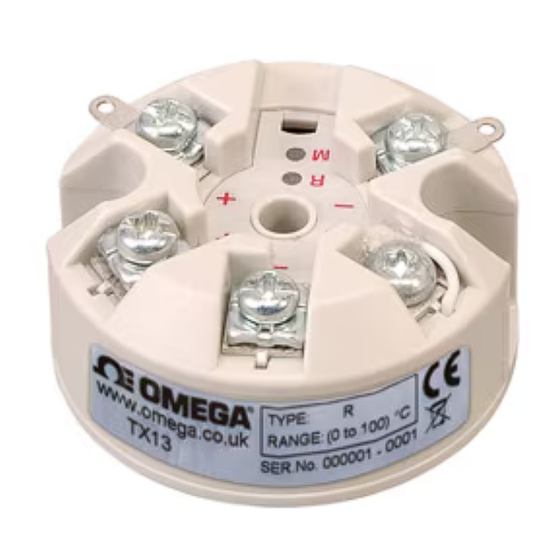
TX13
Push Button
Thermocouple
1.0 DESCRIPTION
The transmitter is an in-head (4 to 20) mA transmitter that connects to a
standard thermocouple sensor and converts the sensors temperature to a
linear temperature (4 to 20) mA signal. The transmitter sensor type and range
can be requested at the time of order, but if desired the user can re-configure
the transmitter parameters by use of a single push button and the range "R"
menu "M" LEDS. Two methods of configuration are available, the first "USER
RANGING" acts only on the transmitter range, similar to the previous design.
The other method "ADVANCED USER CONFIGURATION" offers full
configuration, this level is entered by holding down the push button on
power up. The advanced level has the following menus:
• Menu 1 - Selection of input type, seven popular thermocouples or mV input
• Menu 2 - Select either user push button set range or one of seven fixed ranges
• Menu 3 - Select either up or down scale output on sensor burnout
• Menu 4 - User trim allow trim of output current at high and low range
• Menu 5 - Reset factory default
The addition of fixed ranges to this product allows the user to re-range the
product without the need for specialist equipment. The transmitter input is
isolated.
2.0 RECEIVING AND UNPACKING
Please inspect the packaging and instrument thoroughly for any signs of
transit damage. If the instrument has been damaged, please notify your
supplier immediately.
3.0 SPECIFICATION @ 20 °C
INPUT
Sensor
Range
Accuracy
K
-200 to 1370
± 0.1% of F.S. ± 0.5°C (plus any sensor error)
J
-100 to 1200
± 0.1% of F.S. ± 0.5°C (plus any sensor error)
E
-100 to 1000
± 0.1% of F.S. ± 0.5°C (plus any sensor error)
N
-180 to 1300
± 0.1% of F.S. ± 0.5°C (plus any sensor error)
T
-100 to 400
± 0.2% of F.S. ± 0.5°C (plus any sensor error)
R
-10 to 1760
± 0.1% of F.S. ± 0.5°C (plus any sensor error)
over range 800 to 1600
-10 to 1760
± 0.1% of F.S. ± 0.5°C (plus any sensor error)
S
over range 800 to 1600
mV
-10 to 70
± 0.02% of full scale
Isolation: Tested to 250 Vdc
Sensor Burnout: Either up or down scale output
Cold Junction: Range (-40 to 85)°C; accuracy ± 0.5; tracking ± 0.05°C/°C
Stability: Offset 0. 1°C/°C; span 0.05°C/°C
OUTPUT
Type: Two wire (4 to 20) mA sink
Limits: Low 3.8 mA; high 21.5 mA
Accuracy: (mA out/2000) or 5 uA which ever greater
Loop Effect: ± 0.2 uA/V measured @ 50 Hz 1V (peak to peak)
Thermal Drift: ± 1 uA/°C typical ; ± 1. 5 uA max
Max Load: [(Vsupply - 10)/20] KΩ
GENERAL
Update Time: 0.5 seconds
Response Time: 1 second to reach 90% of final value
Start Up Time: From power up typically 5 seconds
Filter Factor: Adaptive
Ambient Temperature: (-40 to 85)°C
Connection: Screw terminal
Approvals: BS EN 61326; 1998 -electrical equipment for measurent and control
ANNEX A; ANNEX F
Factory Default: (0 to 1000)°C type K upscale burnout (0.0°C user trim)
4.0 INSTALLATION AND WRING
4.1 Mechanical
The transmitter has been specifically designed to fit inside a DIN
standard probe head enclosure, which provides adequate protection from
moisture, dust, corrosive atmosphere etc. All cable entries must be sealed
using the correct size gland. Likewise any probe assembly fitted must be
sealed. Care must be taken when locating the transmitter to ensure the
working ambient temperature range of (-40 to 85)°C is not exceeded. The
transmitter enclosure has a center hole allowing the sensor wired to enter
screw terminals from the transmitter center, this is applicable when the sensor
is mounted directly below the transmitter.
Figure 1
Mounting Holes: Two holes
5.5 mm diameter, 33 mm centers
Center hole sensor wire entry:
4 mm
This datasheet has been downloaded from
4.2 Electrical
Electrical connections to the transmitter are made to the screw terminal pro-
vided on the top face. The correct type of thermocouple wire must be used to
connect sensor, this will normally be provided as part of the probe assembly.
The screw terminals allow for wires to enter either inner or outer direction.
Never attempt to unscrew the spare terminal which secures the factory fitted
cold junction sensor. The terminal is fitted with a tamperproof screw to avoid
accidental adjustment.
The transmitter is protected against reverse connection and over voltage.
If no sensor (input) connection is made the transmitter will go into either up
or down scale output current, depending on configuration setting.
Figure 2 gives connection details, the output is shown connected to a 24V
supply. The load symbol represent any other device connected in the loop,
such as monitoring equipment, panel indicators and loop isolators. The load
value can range from 0 Ω to the max loop load for given supply, refer to
section 3 "max load" for more information.
The transmitter conforms with EC directive BS EN 61326: 1998 when correctly
installed in a termination head providing at least IP20 protection and with
sensor wires less than 3 meters.
Screened or twisted pair wires are recommended for output wires. Always
ensure the (4 to 20) mA loop is grounded at one point this would normally be
at the monitoring equipment or loop power supply.
In normal operation the range "R" LED acts as over-range LED. The menu
LED is always off.
Figure 2
5.0 USER RANGING
The transmitter may be purchased pre-configured, if specified at the time of
order. User ranging is provided to allow the temperature range of the trans-
mitter to be set to a custom range. This configuration level cannot change the
input type. If the input type or other parameters require change, then please
refer to the advances configuration section. To confirm the present input type
set on the transmitter is correct for your application, count the number of
flashes of the range "R" LED at power up then refer to the chart in section 6
"Menu 1" to establish the type set.
The push button is located under the slot in the key hole label, the slot located
next to the menu "M" LED. To press the button use a 3 mm screw driver (flat
blade), inserted into the slot and locate resistance of button key. The button
has a slight click action.
It my be worth noting at this stage the advance user configuration provides
the user with the option of selecting fixed ranges, this may be a more attrac-
tive option if a suitable range is available, as no calibration equipment will be
required.
Configuration will require the following tools and equipment:
• DC Supply (12 to 30) V @ 30 mA
• Thermocouple calibrator
• Thermocouple compensating wire
• Screw driver flat blade 3 mm wide
To re-range the temperature scale follow the instructions below:
• Connect thermocouple calibrator to transmitter input terminals using
• Connect the output terminals to the DC supply, observe polarity.
• Turn DC supply on.
• Set calibrator to the required low scale temperature. Note Range "R"
• Allow 1 minute warm up period.
• To "enter" ranging, press and keep pressed the push button until Range
• The "R" LED will flash at a slow rate for a approximately one
• Set the calibrator to the required high range temperature and allow ten
• Press button to store high range setting, the "R" LED will flicker for
http://www.digchip.com
at this
page
correct thermocouple compensation wire. Observe polarity.
LED if on indicates input connection error or input out of range, please
check input.
"R" LED flashes at a slow rate, then release button.
second during which period the low scale range is stored. Once the
store is complete the "R" LED will flash at a medium rate
indicating the transmitter is ready to store the high range setting.
seconds.
one second before the transmitter returns to normal operation. The
transmitter is now re-ranged.
Advertisement

Related Manuals for Omega TX13


Summary of Contents for Omega TX13
- Page 1 Cold Junction: Range (-40 to 85)°C; accuracy ± 0.5; tracking ± 0.05°C/°C The transmitter may be purchased pre-configured, if specified at the time of e-mail: info@omega.com Stability: Offset 0. 1°C/°C; span 0.05°C/°C order. User ranging is provided to allow the temperature range of the trans- mitter to be set to a custom range.
- Page 2 (°C) (°C) (°C) Purchase Order number to cover the COST of the repair, form, in whole or in part, without the prior written consent of OMEGA User Ranged Model and serial number of the product, and 0 to 1000 0 to 400...
Need help?
Do you have a question about the TX13 and is the answer not in the manual?
Questions and answers