Advertisement
Quick Links
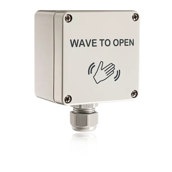
DESCRIPTION
1
2
1. faceplate
2. microwave motion sensor
3. connector
4. housing
TECHNICAL SPECIFICATIONS
Technology
Detection Mode
Radiated Frequency
Radiated Power Density
Supply Voltage
Current Consumption
Temperature Range
Enclosure Rating
Sensing Zone *
Output
Relay contact rating (max voltage)
Relay contact rating (max current)
Max switching power
Output Hold Time
Temperature Range
Material
Certification
* Sensing Zone is dependent upon
•
Size (area) of object
•
Orientation of object
•
Speed of object
•
Environmental conditions
* Use of the device outside the intended application cannot be guaranteed by the manufacturer.
75.5746.04 MS-09 20151020
MAGIC SWITCH: MS09
NEMA 4 | Touchless | Activation Sensor
10MS09TL (shown)
Text & Logo
Microwave - Doppler Radar (24.125 GHz)
Motion (bidirectional)
24.125 GHz
5 mW/cm
12 to 24VAC ± 10%
12 to 24VDC +30% / -10%
< 1.2W
-4°F to + 131°F ( -20°C to +55°C)
NEMA 4
4 - 24 inches (adjustable)
Relay with switch-over contact (voltage free)
60 VDC / 125 VAC
1 A (resistive)
30 W (DC) / 60 VA (AC)
0.5 s (in pulse mode)
-4°F to +131°F
ABS / PC
Electromagnetic compatibility (EMC) according to
2004/108/EC
FCC: G9B-MS08 / 2ABWS-10TD900PB
IC: 4680A-MS08 / 4680A-10TD900PB
10MS09L
Logo Only
4
3
Screw (x4)
2
Specifications are subject to change without prior notice.
Page 1 of 4
Advertisement

Related Manuals for Halma BEA MS09


Summary of Contents for Halma BEA MS09
- Page 1 MAGIC SWITCH: MS09 NEMA 4 | Touchless | Activation Sensor 10MS09TL (shown) 10MS09L Text & Logo Logo Only DESCRIPTION 1. faceplate 2. microwave motion sensor 3. connector 4. housing Screw (x4) TECHNICAL SPECIFICATIONS Technology Microwave - Doppler Radar (24.125 GHz) Detection Mode Motion (bidirectional) Radiated Frequency...
- Page 2 PRECAUTIONS The door control unit Only trained and Always test the proper The warranty is invalid if and the door cover qualified personnel operation of the unauthorized repairs are profile must be correctly may install and setup installation before made or attempted by grounded.
- Page 3 SETTINGS & ADJUSTMENTS Toggle Mode DETECTION ZONE - potentiometer Potentiometer COUNTERCLOCKWISE - decrease (4’’ minimum) Output Mode Switch 4” CLOCKWISE - increase (24’’ maximum *) 24” Pulse Mode OUTPUT MODE - slide switch PULSE - switch down TOGGLE - switch up * Maximum Detection Zone will vary depending on size (area), 4”...
- Page 4 FCC: G9B-21019 This device complies with Part 15 of the FCC Rules. Operation is subject to the following two conditions: (1) this device may not cause harmful interference, and (2) this device must accept any interference received, including interference that may cause undesired operation.