
Related Manuals for Halma BEA ULTIMO


Summary of Contents for Halma BEA ULTIMO
- Page 1 ULTIMO ACTIVATION AND SAFETY SENSOR FOR Visit website for available languages AUTOMATIC, SLIDING DOORS of this document. 75.0034.02 ULTIMO 20211013 Page 1 of 16...
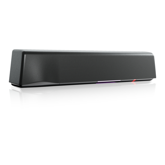
- Page 2 DESCRIPTION cover light pipe radar antenna AIR receiver AIR emitter [for internal use only] AIR curtain angle adjustment knob 10. main adjustment knob 11. main connector 12. [for future development] Page 2 of 16 75.0034.02 ULTIMO 20211013...
-
Page 3: Technical Specifications
TECHNICAL SPECIFICATIONS Mounting height 6’6” – 11’6” Detection mode motion and presence Technology microwave doppler radar and active infrared (AIR) with background analysis Radar detection speed (min) 2 in/s AIR response time (typ.) < 200 ms (max. 500 ms) Radar transmitter frequency 24.150 GHz radiated power... -
Page 4: Led Signals
READ BEFORE BEGINNING INSTALLATION/PROGRAMMING/SETUP LED SIGNALS COLORS BEHAVIORS (green) LED flashes LED flashes red-green Motion detection (red) LED flashes quickly Presence detection LED is off (white) LED flashes x times IR synchronization INSTALLATION The sensor should be Do not cover the sensor. Avoid moving objects and Avoid highly reflective mounted securely to avoid... -
Page 5: Mounting And Wiring
MOUNTING & WIRING MOUNTING Using the provided mounting template, mount the sensor center over the clear opening, ensuring that the bottom of the sensor is no higher than 5 inches from the bottom of the door header. Route the harness (20.5349) using the wire stay as shown in the exploded view of the mounting illustration. Sensor connectivity (power and relays) must utilize only the supplied harness. - Page 6 READ BEFORE BEGINNING PROGRAMMING/SET-UP HOW TO USE THE LCD DISPLAY DURING NORMAL FUNCTION negative display = active output motion To adjust contrast, push and turn the gray button simultaneously. During normal function only. FACTORY VALUE VS. SAVED VALUE displayed value displayed value factory value saved value...
-
Page 7: How To Use The Remote Control
READ BEFORE BEGINNING PROGRAMMING/SETUP HOW TO USE THE REMOTE CONTROL UNDERSTANDING LED ACTIVITY After unlocking, the red LED To end an adjustment If the red LED flashes quickly after unlocking, you need flashes and the sensor can be session, always lock the to enter an access code from 1 to 4 digits. - Page 8 RADAR FIELD The size of the detection field varies according to the mounting height and parameter settings of the sensor. Tilt the radar antenna up to increase the depth and down to decrease. The following graphics are representations – not default settings. ANGLE Tilt the antenna up to adjust the depth outward and down to adjust inward from the doorway.
- Page 9 ACTIVE INFRARED SAFETY FIELD NUMBER OF CURTAINS / POSITION OF CURTAINS (IR:CURTAINS, MENU 1) Choose the number and position of the AIR curtains based on your application. The sensor is defaulted to Non-Threshold setting (3). If threshold is desired, you may choose Threshold setting 1, 2, 4, or 5;...
- Page 10 ACTIVE INFRARED SAFETY FIELD ANGLE (cont.) THRESHOLD 2. If necessary, adjust the AIR curtain angles using the red adjustment knob. Ensure AIR curtain positioning reflects IR:Curtains on the LCD screen. CLOSER CLOSER NON-THRESHOLD AWAY AWAY default 3. When in Threshold mode, verify correct positioning of the threshold curtain: First, turn on the red spots, and then verify that either C1 is at least in line with the moving door panel (see image below, left) or *preferred* through the door opening (see image below, right).
-
Page 11: Push Button
ACTIVE INFRARED SAFETY FIELD ULTI-SYNC: AUTOMATIC SAFETY FIELD SYNCHRONIZATION ULTI-SYNC is used to eliminate AIR crosstalk when safety fields are overlapping in the threshold of the door or when safety fields are overlapping side-to-side. ULTIMO will automatically synchronize its safety field when an overlapping safety field is detected. - Page 12 Page 12 of 16 75.0034.02 ULTIMO 20211013...
- Page 13 75.0034.02 ULTIMO 20211013 Page 13 of 16...
- Page 14 Page 14 of 16 75.0034.02 ULTIMO 20211013...
-
Page 15: Troubleshooting
TROUBLESHOOTING ORANGE LED flashes The sensor signals an Replace sensor. internal fault. ORANGE LED flashes The power supply voltage Check power supply voltage in Diagnostics menu is too low/high. (menu 3) of the LCD. Check wiring. ORANGE LED flashes Radar communication error Check the connection at the radar. - Page 16 TROUBLESHOOTING (cont.) The LED and the LCD No power to sensor. Check wiring. displays are off Check for correct power supply. The reaction of Incorrect output Ensure that the sensor output configuration the door does not configuration / wiring. matches what the door control is expecting. correspond with the Check sensor wiring.
Need help?
Do you have a question about the BEA ULTIMO and is the answer not in the manual?
Questions and answers