Advertisement
Please keep for further use
Designed for colour printing
Other use of the device is outside the permitted purpose and can not be
guaranteed by the manufacturer. The manufacturer cannot be held responsible
for incorrect installations or inappropriate adjustments of the sensor.
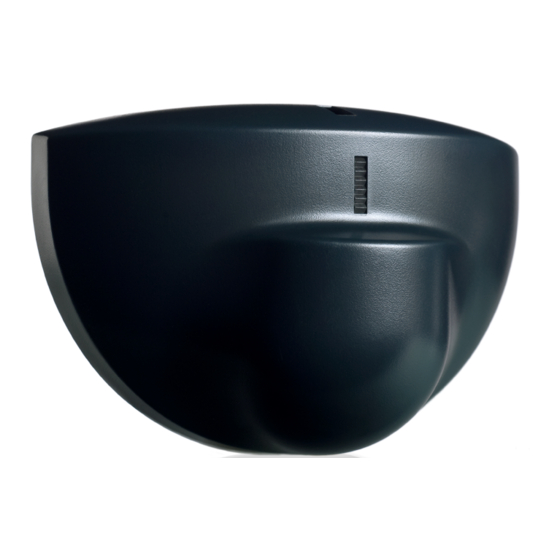
DESCRIPTION
1
2
3
1.
main connector
2.
potentiometer for field size adjustment
3.
radar antenna
4.
DIP-switch
5.
cover
TECHNICAL SPECIFICATIONS
Technology:
Transmitter frequency:
Transmitter radiated power:
Transmitter power density:
Detection mode:
Min. detection speed:
Supply voltage:
Mains frequency:
Max power consumption:
Output:
Max. contact voltage:
Max. contact current:
Max. switching power:
Mounting height:
Degree of protection:
Temperature range:
Dimensions:
Tilt angles:
Material:
Weight:
Cable lenght:
Conformity:
Specifications are subject to changes without prior notice.
Measured in specific conditions
SEAGLE TWO
BIDIRECTIONAL OPENING SENSOR
FOR AUTOMATIC DOORS
microwave doppler radar
24.150 GHz
< 20 dBm EIRP
< 5 mW/cm²
motion
5 cm/s (measured in sensor axis)
12 V to 24 V AC ±10%; 12 V to 24 V DC +30% / -10%
50 to 60 Hz
< 2 W
relay (free of potential change-over contact)
42 V AC/DC
1 A (resistive)
30 W (DC) / 60 VA (AC)
from 1.8 m to 3 m
IP54
from -20 °C to + 55 °C
120 mm (L) x 80 mm (H) x 50 mm (W)
0° to 90° vertical; -30° to +30° lateral
ABS
120 g
2.5 m
RED 2014/53/EU ; 2011/65/EU
4
5
Advertisement
Table of Contents

Related Manuals for Halma BEA SEAGLE TWO


Summary of Contents for Halma BEA SEAGLE TWO
- Page 1 Please keep for further use Designed for colour printing SEAGLE TWO Other use of the device is outside the permitted purpose and can not be BIDIRECTIONAL OPENING SENSOR guaranteed by the manufacturer. The manufacturer cannot be held responsible for incorrect installations or inappropriate adjustments of the sensor. FOR AUTOMATIC DOORS DESCRIPTION main connector...
- Page 2 APPLICATIONS Wall mounting above sliding or Ceiling mounting in front of sliding, revolving doors revolving or swing doors (outside of the door motion range) OPENING THE SENSOR Before fixing After fixing TIPS Do not touch electronical Avoid vibrations. Do not cover the sensor. Avoid proximity to neon parts.
- Page 3 MOUNTING & WIRING Apply the mounting template. Pull the cable through the hole Fix the sensor firmly. Drill 1 hole for the cable and and connect the wires as follows: pull it through. 1 - BROWN - POWER SUPPLY 2 - GREEN - POWER SUPPLY Drill 2 holes for the screws.
- Page 4 TROUBLESHOOTING The door remains The sensor power is off. Check the wiring and the power supply. closed. The LED is OFF. The door does not Change the output configuration setting on Improper output react as expected. each sensor connected to the door operator. configuration on the sensor.
Need help?
Do you have a question about the BEA SEAGLE TWO and is the answer not in the manual?
Questions and answers