
Related Manuals for Halma LZR-Widescan


Summary of Contents for Halma LZR-Widescan
- Page 1 -WIDESCAN ® OPENING, PRESENCE & SAFETY* SENSOR FOR INDUSTRIAL DOORS Download the LZR WIDESCAN installation app! User’s Guide for software version SW 0400 and higher (refer to tracking label on product) * please refer to page 4...
- Page 2 INSTALLATION & MAINTENANCE TIPS INSTALLATION & MAINTENANCE Avoid extreme Do not cover Avoid moving objects in Avoid exposure to vibrations. the laser window screens. the detection field. sudden and extreme temperature changes. Do not use aggressive Avoid direct exposure to Keep the protection film Wipe the laser window products or dry towels to...
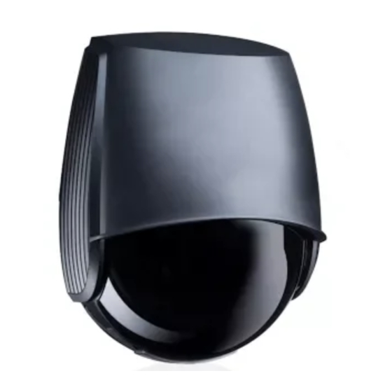
- Page 3 DESCRIPTION The LZR®-Widescan is an industrial door sensor with opening and presence features. main connector LCD-screen protection film 10. keypad laser window 11. tilt angle adjustment screw (1x) USB cap 12. parallel angle adjustment screw (2x) LED-display 13. lateral angle lock screw (1x) cover 14.
- Page 4 BASIC PRINCIPLES: FUNCTIONS & OBJECT There are 3 main functions that create 3 overlapping detection fields with certain detection characteristics each: DOOR OPENS IF: - motion in motion field - certain object type - certain direction DOOR DOES NOT CLOSE IF: - presence in presence field - certain object type DOOR DOES NOT CLOSE IF:...
- Page 5 LED-SIGNAL LED flashes LED flashes LED flashes LED flashes LED is off LED is on quickly slowly x times SETTINGS DETECTION GENERAL All fields Remote control session Motion detection Motion field Pull cord detection Teach-in status Pull cord Troubleshooting Presence detection Presence field No smartphone connected Safety detection...
- Page 6 HOW TO ADJUST THE SENSOR BY REMOTE CONTROL If the red LED flashes quickly after unlocking, enter To end an adjustment After unlocking, the red an access code from 1 to 4 digits. If you do not LED flashes and the sensor session, always lock the know the access code, cut and restore the power can be adjusted by remote...
-
Page 7: Mounting And Wiring
MOUNTING & WIRING Mounting height: as high as possible in acc. to the limitations in the Technical specifications The size of the detection field depends on the mounting height. Mounting position: centre of door or upper left corner. Mounting on the right side of the door should be avoided. The UNIVERSAL MOUNTING BRACKET can be used if the environment requires it. - Page 8 POSITIONING OF DETECTION FIELD First of all, remove the blue protection film from the laser window. If the sensor is mounted in the center of the door, follow steps to adjust the field. If the sensor is mounted on the left (or right side*), follow all steps described on this page. Note that right side mounting could alter the performance of the motion detection LCD DISPLAY LONG...
- Page 9 TEACH-IN: INSTALL - Make sure the blue protection film is removed and the sensor is closed! - Make sure the laser window is free from dust and/or water drops. - The teach-in zone (square in front of the 2 visible spots) must be empty and even. If not, see troubleshooting. - This teach-in must be launched each time a sensor’s position/orientation has been changed.
- Page 10 OVERVIEW OF REMOTE CONTROL SETTINGS (OPTIONAL) install Teach-in corridor corner Presettings The service mode deactivates the presence and safety detection during 15 minutes and can be useful during an installation, Service Mode a mechanical teach-in of the door or maintenance work. Exit the service mode by using the same sequence. full: complete reset of all values Factory Reset partial...
- Page 11 OVERVIEW OF REMOTE CONTROL SETTINGS (OPTIONAL) mot or mot/pull/ mot/pull/ pull motion+ motion+ motion+ Out 1 Function OUT1 OUT2 REL motion change pres pull safe cord & height & speed pres/ presence Out 2 Function presence safety change safety & height pres/ pres Relay Function...
- Page 12 MOTION FIELD WIDTH 000 cm 999 cm (no field) FIELD DEPTH 000 cm 999 cm OBJECT TYPE vehicle vehicle XL (WH) vehicle XL (WH): detects large vehicles; rejects bicycles & narrow forklifts vehicle: detects all types of vehicles; rejects pedestrians any: detects all objects DIRECTION uni INV...
- Page 13 PRESENCE ..FIELD WIDTH 000 cm 999 cm (no field) ..FIELD DEPTH 000 cm 999 cm 300 cm ..OBJECT TYPE vehicle vehicle XL (WH) vehicle XL (WH): detects large vehicles; rejects bicycles & narrow forklifts vehicle: detects all types of vehicles; rejects pedestrians any: detects all objects SAFETY ..
- Page 14 VIRTUAL PULL CORD The door only opens when an object is detected in one of the three virtual pull cord zones during the chosen min. presence time (factory value : 2 seconds). In order to use this function: - the sensor must know its environment: teach-in install is OK. - the corresponding wires must be connected to the door activation input (out 1 by default) - the output or relay function must be set to motion or pull cord (factory value) or pull cord.
- Page 15 HEIGHT TRIGGER All objects higher than 2.25 m will activate the selected output. This option is typically used to open the door completely or partially depending on the height of the object. The wiring and logic of the output configuration are related to the door controller. <...
-
Page 16: Protection Functions
OUT 1 DOOR ACTIVATION FUNCTIONS Motion Motion or pull cord Motion or pull cord or safety Motion or pull cord or presence Pull cord Motion + Motion + and height Motion + and speed OUT 2 PROTECTION FUNCTIONS Presence Safety Presence or safety Presence and height RELAY... - Page 17 CHOSEN SETTINGS DATE : ....... DATE : ....... DATE : ....DATE : ...... LOCATION : ....LOCATION : ....LOCATION : .... LOCATION : ..... INSTALLER : ....INSTALLER : ....INSTALLER : .... INSTALLER : ..... MOVEMENT Field width Field depth (stop) Field start Object type...
- Page 18 NOTES...
-
Page 19: Troubleshooting
TROUBLESHOOTING The sensor encounters an E1: CPU-XXX Replace sensor. internal problem. The internal power supply Replace sensor. E2: XXX PWR is faulty. The power supply is too low Verify power supply > Diagnostics - LCD. E2: IN SUPPLY or too high. Verify the sensor temperature >... -
Page 20: Technical Specifications
TECHNICAL SPECIFICATIONS Technology LASER scanner, time-of-flight measurement (7 laser curtains) Detection mode Motion, presence, height and speed Max. detection field Width: 1 x mounting height; Depth: 1 x mounting height Thickness of first curtain 0.5 cm / m (mounting height) Mounting height 2 m to 10 m Min.
Need help?
Do you have a question about the LZR-Widescan and is the answer not in the manual?
Questions and answers