Table of Contents
Advertisement
Quick Links
INVERTOR GENERATORS INSTRUCTION MANUAL
READ ALL INSTRUCTIONS AND WARNINGS BEFORE USING THIS PRODUCT.
This manual provides important information on proper operation & maintenance. Every effort has been
made to ensure the accuracy of this manual. These instructions are not meant to cover every possible
condition and situation that may occur. We reserve the right to change this product at any time without
prior notice.
IF THERE IS ANY QUESTION ABOUT A CONDITION BEING SAFE OR UNSAFE,
DO NOT OPERATE THIS PRODUCT!
Visit our website for Troubleshooting / Frequently Asked Questions
H A V E Q U E S T IO N S OR P R O B L E M S ? C O N T A C T C U S T O M E R S E R V IC E F IR S T
B E F O R E R E T U R N IN G T H IS P R O D U C T T O T H E R E T A IL E R
If you experience a problem or need parts for this product, visit our website http://www.buffalotools.com
or call our customer help line at 1-866-460-9436, Monday-Friday, 8 AM - 4 PM Central Time. A copy
of the sales receipt is required.
FOR CONSUMER USE ONLY – NOT FOR PROFESSIONAL USE.
KEEP THIS MANUAL, SALES RECEIPT & APPLICABLE WARRANTY FOR FUTURE
REFERENCE.
ITEM # GEN351KIT30
http://sportsmanseriesbrand.com/generators
Q
Advertisement
Table of Contents

Related Manuals for Sportsman GEN351KIT30


Summary of Contents for Sportsman GEN351KIT30
- Page 1 ITEM # GEN351KIT30 INVERTOR GENERATORS INSTRUCTION MANUAL READ ALL INSTRUCTIONS AND WARNINGS BEFORE USING THIS PRODUCT. This manual provides important information on proper operation & maintenance. Every effort has been made to ensure the accuracy of this manual. These instructions are not meant to cover every possible condition and situation that may occur.
- Page 2 Rated Watts (W) 3000 Rated Frequency (Hz) Phase Single DC Output Voltage (V) Circuit Breaker Amperage (A) Engine Engine Type 4-stroke single cylinder with forced air cooling system Ignition System Non-contact transistor (T.C.I.) Starting System Recoil Item # GEN351KIT30 Invertor Generators...
-
Page 3: Table Of Contents
Air Filter Maintenance ............................22 Changing Fuel Line ..............................22 Spark Plug Maintenance ............................22 Emptying The Fuel Tank ............................22 STORAGE/TRANSPORT PROCEDURES ........................23 TROUBLESHOOTING ..............................24 PARTS DIAGRAM ................................26 EMISSION CONTROL SYSTEM WARRANTY ......................... 31 Item # GEN351KIT30 Invertor Generators... -
Page 4: Recognize Safety Symbols, Words And Labels
Parts replaced during warranty repairs will be considered as part of the original product and will have the same warranty period as the original product. This warranty gives you specific legal rights, and you may have other rights that vary state to state. Item # GEN351KIT30 Invertor Generators... - Page 5 Avoid the use of extension cords if possible. If you choose to use them, be sure they are sized adequately to handle the flow of electricity. An undersized cord can overheat, short out and cause a fire. Item # GEN351KIT30 Invertor Generators...
- Page 6 Caution is necessary when near the engine’s recoil starter. Usage: Prolonged exposure to high noise levels can be hazardous to hearing. Always wear ANSI-approved hearing protection when operating or working around the generator when it is running. Item # GEN351KIT30 Invertor Generators...
- Page 7 • Do not operate an excessive number of electrical devices in excess of the wattage capacity of this generator. • Do not turn on electrical devices until after they are connected to this generator. • Turn off all connected electrical devices before stopping this generator. Item # GEN351KIT30 Invertor Generators...
- Page 8 In addition to the previously described safety information, familiarize yourself with all safety and hazard placards on this generator. Item # GEN351KIT30 Invertor Generators...
-
Page 9: Package Contents
If there are missing items, call 1-866-460-9436, Monday - Friday, 8 AM - 4 PM Central Time for customer service. Item List: DC connector wires for charging 12 Volt automotive-type batteries Spark plug wrench 5 ft 9 inch Regulator Hose Kit (YOU MUST USE THE SUPPLIED REGULATOR FOR SAFE OPERATION) Item # GEN351KIT30 Invertor Generators... -
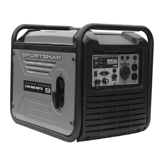
Page 10: Components
11) DC Circuit Protector 12) 12 Volt DC Outlet 13) Grounding Terminal 14) 120 Volt RV Outlet 15) Smart Throttle 16) LP gas inlet 17) Parallel Ports A and B 18) USB Port 19) Alert Indicator Item # GEN351KIT30 Invertor Generators... -
Page 11: Preparing The Generator For Use
When the engine crankcase is full and almost overflowing, the oil level should reach the lower lip of the oil filling opening as shown in Figure 2. 5. Replace the oil filler/dipstick cap and reattach the oil access panel. Figure 1 – Figure 1A Figure 1B Figure 1C Figure 2 - Add Oil Item # GEN351KIT30 Invertor Generators... -
Page 12: Step 2 - Add Gasoline
If using LPG, first connect the regulator that was included with the generator to the Propane Fuel Tank, then connect the other end to the Gas Inlet. Make sure the LPG cylinder is vertical and securely positioned. Item # GEN351KIT30 Invertor Generators... -
Page 13: Step 3 - Ground The Generator
(See “Changing/Adding Oil” in the “Maintenance/Care” section of this manual). 5. Confirm that the oil filler/dipstick cap is properly screwed in place when finished verifying the oil level. Item # GEN351KIT30 Invertor Generators... -
Page 14: Step 2 - Verify Gas Level
No. 12 AWG (American Wire Gauge) stranded copper wire. The other end of this grounding wire should be connected to a copper or brass grounding rod that is driven into the earth. Grounding codes can vary by location. Contact a local electrician for information on grounding regulations for your area. Item # GEN351KIT30 Invertor Generators... -
Page 15: Starting The Generator
The choke is used to provide an enriched fuel mixture when starting a cold engine. It can be opened and closed by operating the choke rod manually. Choke OUT/OFF Choke IN/ON To Start To Run Figure 4 The Recoil Start is located on the left side of the generator. Item # GEN351KIT30 Invertor Generators... -
Page 16: Using The Generator
(18 Cu. Ft.) 1600 saw - circular (7 1/4 inch) 1500 1500 stereo receiver electric stove - single element 1500 sump pump 1200 television (27 inch color) well water pump (1/3 HP) 1000 2000 Item # GEN351KIT30 Invertor Generators... -
Page 17: Dc Usage
If the DC Circuit Breaker turns off, reduce the load of connected electronic devices until the load is within the specified rated output. To re-establish power, return the DC Circuit Breaker back to the “ON” position Item # GEN351KIT30 Invertor Generators... -
Page 18: Ac Parallel Terminals
Do not pair more than 2 generators. Only use the Sportsman Generator parallel output cable for parallel operation (sold separately). You can use the outlets on the control panel of the generator while operating in parallel. Do not exceed combined load on all outlets 20 amps. - Page 19 Fuel Switch to OFF position and let the engine continue to run until it burns off all remaining gasoline fuel in carburetor. Then turn the propane tank ON. If using propane and you want to switch to gasoline, turn the propane tank OFF and turn the gas Fuel Switch ON. Item # GEN351KIT30 Invertor Generators...
-
Page 20: Stopping The Generator
Never clean this generator with a bucket of water and/or a hose as water can get inside and cause a short circuit or corrosion. Never use gasoline to clean parts of this generator. Item # GEN351KIT30 Invertor Generators... -
Page 21: Checking The Oil Level
TROUBLESHOOTING: IF THE GENERATOR WILL NOT START, DOUBLE CHECK THAT THE OIL LEVEL IS COMPLETELY FULL AND ALMOST OVERFLOWING. Figure 8B – Adding oil Figure 8A – Use 12mm hex wrench to REMOVE bolt and drain oil Item # GEN351KIT30 Invertor Generators... -
Page 22: Air Filter Maintenance
To store this generator for extended time, the fuel needs to be drained from the carburetor. To drain the gasoline from the carburetor turn the fuel valve to the “off” position while the engine is running. The generator will shut down when all the gasoline in the carburetor has been used. Item # GEN351KIT30 Invertor Generators... -
Page 23: Storage/Transport Procedures
2 months to 1 year Empty the fuel tank. (See “Emptying the Fuel Tank” in the “Maintenance/Care” section.) 1 year or more Empty the fuel tank. (See “Emptying the Fuel Tank” in the “Maintenance/Care” section.) Disconnect the spark plug. Item # GEN351KIT30 Invertor Generators... -
Page 24: Troubleshooting
Generator runs but does not support all Short in one of the connected devices. Disconnect any faulty or short-circuited connected electrical devices. electrical loads. Air filter is dirty. Clean or replace air filter. Item # GEN351KIT30 Invertor Generators... - Page 25 Item # GEN351KIT30 Invertor Generators...
-
Page 26: Parts Diagram
PARTS DIAGRAM Item # GEN351KIT30 Invertor Generators... - Page 27 PARTS DIAGRAM Item # GEN351KIT30 Invertor Generators...
- Page 28 PARTS DIAGRAM Valve Assembly Item # GEN351KIT30 Invertor Generators...
- Page 29 PARTS DIAGRAM Item # GEN351KIT30 Invertor Generators...
- Page 30 PARTS LIST Item # GEN351KIT30 Invertor Generators...
-
Page 31: Emission Control System Warranty
Any such part repaired or replaced under warranty will be warranted for the remaining warranty period. (3) Any warranted part that is scheduled for replacement as required maintenance in your Owner’s Manual is warranted Item # GEN351KIT30 Invertor Generators... - Page 32 (a) Purge valves (b) Carbon canister (c) canister Mounting Brackets (d) Fuel Cap (e) Fuel Tank (7) Miscellaneous items used in above systems including: (a) Switches (b) Hoses, belts connectors, and assemblies (8) Air injection system (a) Pulse valve Item # GEN351KIT30 Invertor Generators...
- Page 33 . T h i s w a r r a n t y g i v e s y o u s p e c i f i c l e g a l r i g h t s , a n d y o u m a y h a v e o t h e r r i g h t s t h a t v a r y s t a t e t o s t a t e . Item # GEN351KIT30 Invertor Generators...
- Page 34 . C a u t i o n i s n e c e s s a r y w h e n n e a r t h e e n g i n e ’ s r e c o i l s t a r t e r . Item # GEN351KIT30 Invertor Generators...
- Page 35 . Item # GEN351KIT30 Invertor Generators...
- Page 36 (11) Ground (earth) (12) DC protector terminal (13) DC receptacle (14) AC receptacle (16) Fuel filter (17) Fuel tank cap (18) Fuel pump (19) Recoil starter (20) Fuel cock (21) Oil filler cap (22) Air filter cover Item # GEN351KIT30 Invertor Generators...
- Page 37 D o n o t f i l l a b o v e t h e t o p o f t h e f u e l f i l t e r o r i t m a y o v e r f l o w w h e n t h e f u e l h e a t s u p l a t e r a n d e x p a n d s . l K e e p o p e n f l a m e s a w a y . Item # GEN351KIT30 Invertor Generators...
- Page 38 . Item # GEN351KIT30 Invertor Generators...
- Page 39 Check fuel hose for crack or l damage. Replace if necessary. Exhaust System Check for leakage. Retighten or l replace gasket if necessary Check muffler screen. l Clean / replace if necessary. Carburetor Check choke operation l Item # GEN351KIT30 Invertor Generators...
- Page 40 2 . C h e c k f o r d i s c o l o r a t i o n a n d r e m o v e t h e c a r b o n . Item # GEN351KIT30 Invertor Generators...
- Page 41 1 . R e m o v e t h e f u e l t a n k c a p , d r a i n t h e f u e l f r o m t h e f u e l t a n k . Item # GEN351KIT30 Invertor Generators...
- Page 42 SAE 10W30 Lubricating oil Capacity 7.5 ounce Starting System Recoil Starter Ignition system C.D.I. Spark Plug: Type CMR6A (TORCH) Net dimension L×W×H 395×209×355 Overall dimension L×W 425×230×380 ×H Net Weight 9.2 Kg Gross Weight 11.4Kg Item # GEN351KIT30 Invertor Generators...
- Page 43 Pull the recoil starter until you feel compression. Stop pulling. Clean exterior of the generator and apply a rust inhibitor. Store the generator in a dry, well-ventilated place, with the cover place over it. The generator must remain in a vertical position Item # GEN351KIT30 Invertor Generators...
- Page 44 W I R I N G D I A G R A M Item # GEN351KIT30 Invertor Generators...
- Page 45 Item # GEN351KIT30 Invertor Generators...
- Page 46 Item # GEN351KIT30 Invertor Generators...
- Page 47 Item # GEN351KIT30 Invertor Generators...
- Page 48 Item # GEN351KIT30 Invertor Generators...
- Page 49 Item # GEN351KIT30 Invertor Generators...
- Page 50 Item # GEN351KIT30 Invertor Generators...
- Page 51 Item # GEN351KIT30 Invertor Generators...
- Page 52 EMISSION CONTROL SYSTEM WARRANTY BUFFALO CORPORATION Your Warranty Rights and Obligations Item # GEN351KIT30 Invertor Generators...
- Page 53 Buffalo Corp will not be liable to warrant failures of warranted parts caused by the use of a non-exempted add-on or modified part. Item # GEN351KIT30 Invertor Generators...
- Page 54 (a) Purge valves (b) Carbon canister (c) canister Mounting Brackets (d) Fuel Cap (e) Fuel Tank (7) Miscellaneous items used in above systems including: (a) Switches (b) Hoses, belts connectors, and assemblies (8) Air injection system (a) Pulse valve 201901 Item # GEN351KIT30 Invertor Generators...
Need help?
Do you have a question about the GEN351KIT30 and is the answer not in the manual?
Questions and answers