Table of Contents
Advertisement
Quick Links
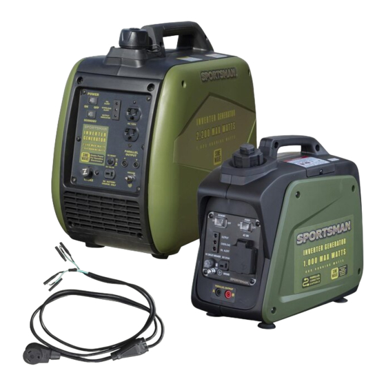
Item # GEN3KIT30A
INSTRUCTION MANUAL
Connect the parallel cables, making sure to first ground the cable. Be certain to match the same
color wire into A and B. Start the GEN2000I first. When it is running you can start GEN1000I-PL.
This should give you a combined max output of 3,000 Surge Watts / 2,500 Running Watts.
201901
1
Advertisement
Table of Contents

Related Manuals for Sportsman GEN3KIT30A


Summary of Contents for Sportsman GEN3KIT30A
- Page 1 Item # GEN3KIT30A INSTRUCTION MANUAL Connect the parallel cables, making sure to first ground the cable. Be certain to match the same color wire into A and B. Start the GEN2000I first. When it is running you can start GEN1000I-PL.
- Page 2 Item # GEN2000I 2200 SURGE WATTS / 1800 RUNNING WATTS GASOLINE INVERTER PORTABLE GENERATOR INSTRUCTION MANUAL READ ALL INSTRUCTIONS AND WARNINGS BEFORE USING THIS PRODUCT. This manual provides important information on proper operation & maintenance. Every effort has been made to ensure the accuracy of this manual. These instructions are not meant to cover every possible condition and situation that may occur.
- Page 3 CARBON MONOXIDE Using a generator indoors CAN KILL YOU IN MINUTES Generator exhaust contains carbon monoxide (CO). This is a poison you cannot see or smell. If you can smell the generator exhaust, you are breathing CO. But even if you cannot smell the exhaust, you could be breathing CO.
- Page 4 Model GEN2000I 2200 Surge Watts / 1800 Running Watts This unit is a Gasoline Fuel powered Inverter generator. FEATURES: • 2200 Surge Output / 1800 Running Watts • 120V Operation • 3.0 HP Engine, 4 Stroke , 4650 RPM • Displacement (CC): 79.7 •...
-
Page 5: Table Of Contents
TABLE OF CONTENTS RECOGNIZE SAFETY SYMBOLS, WORDS AND LABELS ....................5 PACKAGE CONTENTS PACKAGE CONTENTS ............................10 COMPONENTS ..............................11 PREPARING THE GENERATOR FOR USE ........................11 Using This Generator For The First Time ....................... 12 Step 1 – Add Oil ............................12 Step 2 –... -
Page 6: Recognize Safety Symbols, Words And Labels
RECOGNIZE SAFETY SYMBOLS, WORDS AND LABELS What You Need to Know About Safety Instructions Warning and Important Safety Instructions appearing in this manual are not meant to cover all possible conditions and situations that may occur. Common sense, caution and care must be exercised when operating or cleaning tools and equipment. - Page 7 IMPORTANT SAFETY INSTRUCTIONS STOP! Before using this generator and if you have any questions regarding the hazard and safety notices listed in this manual and/or on this generator, call 1-866-460-9436, Monday - Friday, 8 AM - 4 PM Central Time. Carbon Monoxide Gas: When in operation, the exhaust from this generator contains poisonous carbon monoxide gas.
- Page 8 Usage: Misuse of this generator can damage it or shorten its life. • Use this generator only for its intended purpose. • Operate this generator only on a dry, level surface. • Allow this generator to run for several minutes before connecting any electrical devices. •...
- Page 9 GEN2000I 2200 Surge Watt / 1800 Running Watt Portable Gasoline Inverter Generator Manual...
- Page 10 In addition to the previously described safety information, familiarize yourself with all safety and hazard notices on this generator. GEN2000I 2200 Surge Watt / 1800 Running Watt Portable Gasoline Inverter Generator Manual...
-
Page 11: Package Contents
PACKAGE CONTENTS The following items are supplied with this Model GEN2000I Portable Gasoline Inverter Generator. Verify that all items are included. STOP! If there are missing items, call 1-866-460-9436, Monday - Friday, 8 AM - 4 PM Central Time for customer service. DO NOT RETURN THIS GENERATOR TO THE RETAILER. -
Page 12: Components
GENERATOR COMPONENTS Observe the locations and functions of the various components and controls of this generator. To prevent electrical shock from faulty appliances, the generator should be grounded. Connect a length of heavy wire between the ground terminal and the ground source. Consult with a qualified electrician to ensure compliance with local electrical codes. -
Page 13: Preparing The Generator For Use
PREPARING THE GENERATOR FOR USE Using this Generator for the First-Time STOP! The following section describes the required steps for preparing this generator for the first use. Failure to correctly perform these steps can damage this generator and/or shorten its life. If still unsure about how to perform any of these steps after reading this section, call 1-866-460-9436 Monday - Friday, 8 AM - 4 PM Central Time for customer service. -
Page 14: Step 2 - Connect Fuel
Step 2 – Connect Fuel Add Unleaded gasoline only with an octane rating of 87 or higher. Maximum Capacity: 1.0 Gallons Pre-Operation Check List Step 1 Check that the gas supply source is in good condition. Check that the gas inlet connection is tightly fixed and not leaking. Step 2 CHOKE VALVE GRIP is at CHOKE (CLOSE) position. -
Page 15: Step 3 - Ground The Generator
Step 3 - Ground the Generator Failure to properly ground this generator can result in electrocution. Ground this generator by tightening the grounding nut against a grounding wire as illustrated in Figure 3. A No. 12 AWG (American Wire Gauge) stranded copper wire is generally an acceptable grounding wire. -
Page 16: Step 3 - Ground The Generator
Step 3 - Ground the Generator Failure to properly ground this generator can result in electrocution. Ground this generator by tightening the grounding nut against a grounding wire as previously illustrated in Figure 3. A generally acceptable grounding wire is a No. 12 AWG (American Wire Gauge) stranded copper wire. The other end of this grounding wire should be connected to a copper or brass grounding rod that is driven into the earth. -
Page 17: Using The Generator
USING THE GENERATOR After the engine has been running for several minutes, electrical devices may be connected to this generator. AC Usage Electrical devices running on AC current may be connected according to their wattage requirements. The rated (running) and surge wattage: Model GEN2000I Rated (Running) Wattage 1800 Model GEN2000I Surge Wattage... - Page 18 Connect electrical devices to this generator according to the following procedure: 1. Allow the engine to run for several minutes after it has been started. 2. Confirm that the electrical device is switched off prior to plugging it into this generator. Connect only electrical devices that are in good working order.
-
Page 19: Ac Parallel Usage
AC PARALLEL TERMINALS The parallel port terminals are used with a parallel kit (sold separately). It will allow two generators to be linked to increase output. The black and white wire connections are non-polarized and can be inserted into either the left or right ports. -
Page 20: Dc Usage
DC Usage The DC outlet is only for recharging 12 Volt automotive-type batteries. Do not connect any other device to this outlet. Use this generator only for recharging 12 Volt batteries. NEVER attempt to jumpstart a car with this generator. Failing to use the correct procedure can cause a battery to explode, seriously injuring anyone nearby. -
Page 21: Maintenance/Care
MAINTENANCE/CARE Proper routine maintenance of this generator is essential for safe, economical, and trouble-free operation. It will help prolong the life of this generator as well as help reduce air pollution. Perform maintenance checks and procedures according to the schedule in Figure 10. STOP! If you have questions about maintenance procedures described in this manual, call 1-866-460-9436 , Monday - Friday, 8 AM - 4 PM Central Time. -
Page 22: Changing/Adding Oil
Figure 11 - Checking the Oil Changing/Adding Oil The oil level in this generator should be checked before each use. When the oil level is low, add oil until the level is sufficient to operate this generator. To drain the oil from this generator: The oil should be changed after the first 20 hours of operation. -
Page 23: Air Filter Maintenance
GEN2000I 2200 Surge Watt / 1800 Running Watt Portable Gasoline Inverter Generator Manual... -
Page 24: Spark Arrestor
GEN2000I 2200 Surge Watt / 1800 Running Watt Portable Gasoline Inverter Generator Manual... -
Page 25: Troubleshooting
Troubleshooting GEN2000I 2200 Surge Watt / 1800 Running Watt Portable Gasoline Inverter Generator Manual... -
Page 26: Specifications
SPECIFICATIONS GEN2000I 2200 Surge Watt / 1800 Running Watt Portable Gasoline Invertor Generator Generator Type Revolving Magnetic Field, Self Exciting, Multi-Pole, Single Phase AC Output Rated Wattage (W) 1800 Surge Wattage (W) 2200 Rated Voltage (V) Rated Amperage Rated Frequency (Hz) Phase Single DC Output... -
Page 27: Parts Diagram
PARTS DIAGRAM GEN2000I 2200 Surge Watt / 1800 Running Watt Portable Gasoline Inverter Generator Manual... - Page 28 GEN2000I 2200 Surge Watt / 1800 Running Watt Portable Gasoline Inverter Generator Manual...
- Page 29 PARTS DIAGRAM GEN2000I 2200 Surge Watt / 1800 Running Watt Portable Gasoline Inverter Generator Manual...
- Page 30 PARTS DIAGRAM GEN2000I 2200 Surge Watt / 1800 Running Watt Portable Gasoline Inverter Generator Manual...
-
Page 31: Wiring Diagram
GEN2000I 2200 Surge Watt / 1800 Running Watt Portable Gasoline Inverter Generator Manual... -
Page 32: Emissions Control System Warranty
EMISSION CONTROL SYSTEM WARRANTY BUFFALO CORPORATION Your Warranty Rights and Obligations The California Air Recourse Board, U.S. EPA and Buffalo Corp. are pleased to explain the Emission Control System Warranty on your 2018 model year new outdoor power equipment engine. California In California, new spark-ignited small off-road equipment engines must be designed, built and equipped to meet the State’s stringent anti-smog standards. - Page 33 (6) The engine owner must not be charged for diagnostic labor that leads to the determination that a warranted part is in fact defective, provided that such diagnostic work is performed at a warranty station. (7) Buffalo Corp. is liable for damages to other engine components proximately caused by a failure under warranty of any warranted part. (8) Throughout the engine warranty period stated above, Buffalo Corp.
- Page 34 Item # GEN1000I-PL 1,000 MAX WATTS INVERTER GENERATOR INSTRUCTION MANUAL R E A D A L L I N S T R U C T I O N S A N D W A R N I N G S B E F O R E U S I N G T H I S P R O D U C T . This manual provides important information on proper operation &...
- Page 35 Notice Regarding Emissions: Engines certified to comply with California and U.S. EPA emission regulations for SORE (Small Off Road Equipment) are certified to operate on regular unleaded gasoline and may include the following emission control systems: Three-Way Catalyst (TWC) (if equipped), and Engine Modifications (EM). Legal Requirements: Federal and/or State Occupational Safety and Health Administration (OSHA) regulations, local codes, and/or ordinances may apply to the intended use of this generator.
- Page 36 Flammable Gasoline: This generator may emit highly flammable and explosive gasoline vapors, which can cause severe burns or even death. A nearby open flame can lead to an explosion even if not directly in contact with gasoline. • Do not operate this generator near open flame. •...
- Page 37 This generator produces powerful voltage, which can result in electrocution. Powerful Voltage: • ALWAYS ground this generator before using it. (See “Ground the Generator” section in this manual). • Only electrical devices should be plugged into this generator, either directly or with an extension cord. NEVER connect a building electrical system to this generator without a qualified electrician.
- Page 38 Misuse of this generator can damage it or shorten its life. Usage: • Use this generator only for its intended purpose. • Operate this generator only on a dry, level surface. Do not secure the generator with a chain or rope, which would prevent it from being moved in an emergency.
- Page 39 FEATURES: •0.55 Gallon Fuel Tank •1,000 Watts Max/800 W Min AC output •5,000 RPM •40cc, 4 stroke •Low oil shutdown •Recoil Start •Run Time : 6.3 Hours at 50% load •Noise Level : 56db at 0% load @23 Ft •1.3 HP •7.5 ounces Oil •...
- Page 40 2) ECONOMY CONTROL SWITCH When the economy control switch is turned “ON”, the economy control unit controls the engine speed according to the connected load. The results are better fuel connection and less noise. (Turn OFF when using less voltage.) 3)...
- Page 41 CHECK ENGINE OIL Remove side panel, remove oil filler cap and check the engine oil level. Make sure the engine oil is at the upper level of the oil filler hole. l WARNING: The generator has been shipped without engine oil. Fill with oil or it will not start. Do not tilt the generator when adding engine oil.
- Page 42 DC APPLICATION This usage is applicable to 12V battery charging. Be sure the Economy Control Switch is turned off while charging the battery. PARALLEL OUTLETS Parallel two generators through using Parallel terminal connecting the special terminal. the parallel operating need two generators with parallel function and special cable.
- Page 43 MAINTENANCE CHART Regular maintenance is important for the best performance and safe operation. Initial Every Every Every Pre-operation Item Remarks 1 months 3 months 6 months 12 months Check (daily) or 20 Hr or 50 Hr or 100 Hr or 300 Hr Spark Plug Check condition adjust gap and clean.
- Page 44 ENGINE OIL REPLACEMENT 1. Place the machine on a level surface and warm up the engine for several minutes. Then stop the engine and turn the fuel cock knob to “OFF”. Turn the fuel tank cap air vent knob clockwise. 2.
- Page 45 FUEL TANK FILTER Remove the fuel tank cap and filter. Clean the filter with solvent. If damaged, replace. Wipe the filter and insert it. Be sure the tank cap is tightened securely. MUFFLER SCREEN l The engine and muffler will be very hot after the engine has been run.
- Page 46 l Faulty ignition system….Consult dealer. Compression insufficient l Worn out piston and cylinder….Consult dealer. Generator won’t produce power Safety device (AC) to “OFF” …Stop the engine, then restart. Safety device (DC) to “OFF” …Press to reset the DC protector STORAGE Long term storage of your machine will require some preventive procedures to guard against deterioration.
- Page 47 Model XY139F-6 Type Air-cooled, 4 cycle, OHV, Gasoline Engine Bore×Stroke mm×mm 39×33.5 Displacement 40 cc Max. Output 0.9KW / 5500rpm Fuel Regular Automobile Gasoline Fuel tank Capacity 0.55 Gallon Rated Continuous Operation 6.3 hr @ 50% load Lubricating oil SAE 10W30 Lubricating oil Capacity 7.5 ounce Starting System...
- Page 48 STORAGE INSTRUCTIONS Long term storage of your machine will require some preventive procedures to guard against deterioration. 1. DRAIN THE FUEL Remove the fuel tank cap, drain the fuel from the fuel tank 2. E NGINE Remove spark plug, pour in about one tablespoon of SAE 10W30 motor oil into the spark plug hole and ...
- Page 49 WIRING DIAGRAM ...
- Page 50 ...
- Page 51 ...
- Page 52 ...
- Page 53 ...
- Page 54 ...
- Page 55 ...
- Page 56 ...
- Page 57 ...
- Page 58 EMISSION CONTROL SYSTEM WARRANTY BUFFALO CORPORATION Your Warranty Rights and Obligations The California Air Resources Board, U.S. EPA and Buffalo Corp are pleased to explain the Emission Control System Warranty on your 2018 model year outdoor power equipment engine. California In California, new spark-ignited small off-stringent anti-smog standards.
- Page 59 (2) Any warranty part that is scheduled only for regular inspection in your period stated above. Any such part repaired or replaced under warranty will be warranted for the remaining warranty period. (3) Any warranted part that is scheduled for replacement as required maintenance in your Owners Manual is warranted for the period of time before the first scheduled replacement date for that part.
- Page 60 (3) Ignition system including: (a) Spark plug (b) Ignition coil (4) Catalytic muffler assembly including: (a) Muffler gasket (b) Exhaust manifold (c) Catalytic converter if available (5) Crankcase breather assembly including (a) Breather connection tube (6) Fuel tank evaporative emissions control system including: (a) Purge valves (b) Carbon canister (c) canister Mounting Brackets (d) Fuel Cap (e) Fuel Tank (7) Miscellaneous items used in above systems including: (a) Switches (b) Hoses, belts connectors, and assemblies (8) Air injection system (a) Pulse valve...
Need help?
Do you have a question about the GEN3KIT30A and is the answer not in the manual?
Questions and answers