
Related Manuals for Rosemount P330


Summary of Contents for Rosemount P330
- Page 1 00809-0100-4776 English Rev. AA Model P330 Pressure Validator Installation and Operation Manual...
- Page 3 Read this manual before working with the product. For personal and system safety, and for optimum product performance, make sure you thoroughly understand the contents before installing, using, or maintaining this product. Within the United States, Rosemount Inc. has two toll-free assistance numbers. Customer Central: 1-800-999-9307 ( 7:00 a.m.
- Page 4 Rosemount Model P330 Pressure Validator...
-
Page 5: Table Of Contents
Table of Contents IMPORTANT Procedures and instructions in this manual may require special precautions to ensure the safety of the personnel performing the operations. Refer to the safety messages at the beginning of each section before performing any operations. Introduction ..........1-1 SECTION 1 Product Description . - Page 6 Turning the 24 V Power Source On or Off ....4-9 Overview ..........5-1 SECTION 5 Safety Messages .
- Page 7 SECTION 9 Model P330 Specifications ........9-1 Pressure Specifications .
-
Page 9: Introduction
Section 7: Using the Hydraulic Validator This section is for users of the Rosemount Model P330 Hydraulic Validator. It describes procedures and special safety precautions related to using the hydraulic validator. -
Page 10: Product Description
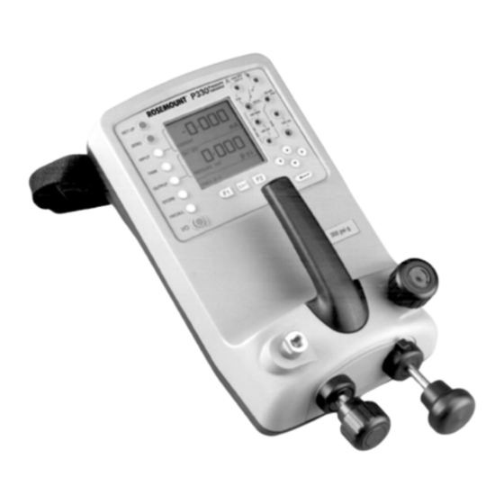
Rosemount Model P330 Pressure Validator The Rosemount Model P330 Pressure Validator is a rugged and PRODUCT DESCRIPTION portable precision validator available either in a pneumatic or a hydraulic version. It is used primarily for validating transmitters and systems over the range of –15 to 300 psi (–1 to 20 bar), HAV version to 6,000 psi (400 bar). -
Page 11: Shipping List
Introduction SHIPPING LIST Item Part number Rechargeable Batteries 00330-0013-0001 Charger 110 V ac 00330-0014-0001 Lead Set 00330-0015-0001 Carrying Case 00330-0016-0001 User Manual 00809-0100-4776... - Page 12 Rosemount Model P330 Pressure Validator...
-
Page 13: Overview
Connections OVERVIEW This section describes the power, pressure, and electrical controls of the Model P330 Pressure Validator. Power sources and powering procedures, pressure controls and the pressure-generation procedure, and electrical controls, including a section on test leads, are described in this section. -
Page 14: Installing Batteries
Rosemount Model P330 Pressure Validator NOTE Old batteries can leak and cause corrosion. Never leave discharged batteries in the validator. NOTE If a rechargeable battery pack is installed and the display reads you must charge the batteries before use. BATTERY LOW,... -
Page 15: Charging The Nicad Battery Pack
Hardware Functions To install either the rechargeable NiCad pack or six C cell batteries, proceed as follows: 1. Ensure that the validator is turned off. 2. Unscrew the battery compartment cover and remove it. 3. If there are batteries in the compartment, carefully lift them out. 4. -
Page 16: Pressure Controls
Rosemount Model P330 Pressure Validator NOTE The validator must be powered on in order to charge. The validator may be operated while in charging mode. PRESSURE CONTROLS The pressure controls are used to generate and control pressure during pressure validations. Pressure controls are shown in Figure 2-2 and described in Table 2-1. -
Page 17: Pressure-Generation Procedure
Hardware Functions The pressure-generation procedure is provided in all validation testing PRESSURE-GENERATION procedures. It allows you to become acquainted with the features, PROCEDURE processes, and safety considerations involved with validation testing. Before performing any validation procedures, read the following pressure safety notes carefully. NOTE The pressure test port has a –27 NPT female coupling. -
Page 18: Validation Connections
Rosemount Model P330 Pressure Validator The validation connections are located on the validator control panel. Validation Connections Use these sockets to make electrical connections to the transmitter being tested. Figure 2-3 shows the validation connections. If the transmitter is in an existing power loop, it is said to be External Power vs. -
Page 19: Interface Connections
NiCad battery pack NiCad Battery Pack on page 2-3 CHANGING FUSES The Model P330 Pressure Validator is equipped with internal fuses that can only be changed by your distributor. ADDING AN EXTERNAL NOTE Before using an external sensor for any measurements, a two-point SENSOR (TRANSDUCER) calibration must be carried out. - Page 20 Rosemount Model P330 Pressure Validator...
-
Page 21: Overview
Section Software Functions OVERVIEW This section describes software functions of the Rosemount Model P330 Pressure Validator, which include use of the validator’s keypads and display panel to access the validator’s menus. This information is preliminary and essential to performing all the setup and validation procedures described in this manual. -
Page 22: Display Panel
Rosemount Model P330 Pressure Validator FIGURE 3-1. Model P330 Control Display Panel Panel. Validation Connection Sockets Hard Keys Arrow Keys Enter Key Function Keys Display Panel The display panel is divided into three sections: the input (to validator), the output (from validator), and the status line/soft box. Figure 3-2... -
Page 23: The Keypads
Software Functions Output Display display shows output from the validator. In the same OUTPUT example, in Pressure-to-Voltage task mode, the validator sends a pressure to a transmitter and receives a voltage signal from a transmitter. The display is pressure, as shown in Figure 3-2 OUTPUT above. - Page 24 Rosemount Model P330 Pressure Validator Arrow Keys TABLE 3-2. Arrow Key Uses. Arrow Key Uses 1. Select from a list of options to highlight options listed in the display panel. When the desired option is highlighted, press to select it.
- Page 25 Software Functions TABLE 3-4. Setup Key Menu Tree. 1. Sets display lighting mode 2. Sets display timeout period, in seconds BACKLIGHT NONE Turns S mode off TORE Takes a “picture” of the screen and saves it. 20 snapshot locations SNAPSHOT available.
- Page 26 Rosemount Model P330 Pressure Validator TABLE 3-6. Input Key Menu Tree. SELECT UNITS OF PRESSURE UNITS (F2) Select units of pressure PRESSURE INT Sets input to internal source TARE PRESSURE EXT Tares the display or a manually Sets input pressure entered value off a display reading.
- Page 27 Software Functions TABLE 3-7. Task Key Menu Tree. BASIC P-I or P-V: Press F1 to switch mode. Zero only active hard key Pressure-Current Pressure-Voltage Current-Pressure Converter P-Display Use with Datalog to store data points P-Switch Switch test. Use F1 to run/stop test. TASK Buzzes at closure.
- Page 28 Rosemount Model P330 Pressure Validator TABLE 3-8. Output Key Menu Tree. SELECT FUNCTION PRESSURE INT 1. Select units of pressure Sets output to internal 2. Turn 24 V power on and off PRESSURE EXT Sets output to external OUTPUT mA STEP LINEAR 4–20 mA...
- Page 29 Software Functions TABLE 3-10. Recall Key Menu Tree. SNAPSHOT RECALL Recalls stored snapshots in in S mode NAPSHOT numerical order. Press C URSOR to advance to next snapshot. DIRECTORY RECALL Recalls a list of saved files. Use in D mode ATALOG function keys to review, erase, and download to a PC.
- Page 30 Rosemount Model P330 Pressure Validator 3-10...
-
Page 31: Overview
Section Validator Setup OVERVIEW This section describes setting the internal parameters and the validation testing parameters of the Rosemount Model P330 Pressure Validator. Internal parameters are: • Display appearance (backlight and contrast) • Memory mode • Settings for pressure units, language, RS232 parameters,... -
Page 32: Setting Internal Parameters
Rosemount Model P330 Pressure Validator Internal parameter setup is done with the key. In Setup, the SETTING INTERNAL SETUP following parameters are set: PARAMETERS • Backlight • Store mode • Contrast • Settings (includes Units, Language, RS232, Powerdown, and Calibration) -
Page 33: Store Mode
Hardware Functions 1. In the menu, use to highlight Press SETUP BACKLIGHT. ENTER 2. On the screen, the box should be BACKLIGHT MODE OF OPERATION highlighted. Press F1 to change the value. The options are ON, OFF, TIMER mode, the backlight stays on. mode, the backlight is off. -
Page 34: Contrast
Rosemount Model P330 Pressure Validator Contrast adjusts the contrast between the display background and Contrast foreground. To adjust the contrast, refer to Figure 4-3 and proceed as follows: FIGURE 4-3. Setting the Contrast. 1. In the menu, use to highlight . - Page 35 Hardware Functions To set units, refer to Figure 4-5 and Figure 4-6 and proceed as follows: FIGURE 4-5. Removing and Selecting Units. 1. In the menu, use to highlight . Press SETTINGS UNITS ENTER menu is displayed. SELECT REGULAR UNITS 2.
- Page 36 Rosemount Model P330 Pressure Validator To set language, refer to Figure 4-7 and proceed as follows: Setting Language FIGURE 4-7. Language Menu. 1. In the menu, use to highlight . Press SETTINGS LANGUAGE ENTER 2. Use to highlight the desired language.
-
Page 37: Setting Validation Parameters
Hardware Functions enables the validator to shut itself off after a user-set Setting Powerdown POWERDOWN period of inactivity. It can be set to must be TIMER POWERDOWN set to in order to turn off automatically after a set time period. TIMER The time period can be between 1 and 120 minutes. -
Page 38: Zeroing The Display
Rosemount Model P330 Pressure Validator Setting units in any task mode other than Basic or Advanced 1. Press the key. OUTPUT 2. Use to highlight . Press UNITS ENTER 3. Use to highlight desired units. Press ENTER 4. If desired units are not listed, refer to Selecting Units on page 4-4. -
Page 39: Turning The 24 V Power Source On Or Off
Hardware Functions 1. Press the key. ZERO The soft box displays the change to ZERO INPUT ZERO OUTPUT depending on the task mode. ZERO INTERNAL SENSOR? 2. To zero the input, press F1. 3. Press F1 again to zero the display, or press F2 to return to the task screen without zeroing the display. - Page 40 Rosemount Model P330 Pressure Validator 4-10...
-
Page 41: Overview
Section Validator Procedures OVERVIEW This section provides procedures for the task modes listed in the TASK key menu. The procedures are not listed in the order they appear on the validator menu; they are grouped by function. • The Pressure-to-Electrical Validations section describes procedures in which the validator outputs a pressure and reads an input in an electrical unit. -
Page 42: Maximum Ratings
Rosemount Model P330 Pressure Validator Ensure that the external transducer is compatible with the pressure medium being used. All Rosemount External Transducers supplied are approved for use with the validator. Before using any other transducer, ensure that the permitted transducer and cable parameters are compatible. -
Page 43: Pressure-To- Electrical Validation Procedures
ELECTRICAL VALIDATION results in either milliamps (current, or I) or volts (V). These are the PROCEDURES most common validation procedures done by the Model P330 Pressure Validator. NOTE The first time the validator is turned on upon shipment from the manufacturer, it is in Basic task mode. - Page 44 Rosemount Model P330 Pressure Validator NOTE In Basic mode, the input displays the validator mode, and the left soft box displays the other selections. For example, if the validator is in Voltage mode, the Input displays and the left soft box displays VOLTAGE, CURRENT.
-
Page 45: Pressure-To-Current (P-I) Mode
Hardware Functions In (P-I) Mode, the validator sends a pressure to the transmitter PRESSURE-TO-CURRENT (outputs), and receives a signal from the transmitter in milliamperes (P-I) MODE (mA). To perform the P-I test, refer to Figure 5-1 and Figure 5-2 for hookup diagrams and proceed as follows: FIGURE 5-1. - Page 46 Rosemount Model P330 Pressure Validator P-I Task Mode Procedure 1. Ensure that the validator is turned off. 2. Open the release valve on the validator. 3. Set the pressure/vacuum knob to + or – as required. 4. Connect the transmitter to the reference pressure port on the validator using a –27 NPT coupling device and a pneumatic...
-
Page 47: Pressure-To-Voltage (P-V) Mode
Hardware Functions In P-V mode, the validator outputs a pressure to a transmitter and PRESSURE-TO-VOLTAGE receives a signal from the transmitter in voltage. Transmitters with a (P-V) MODE 10 V supply and outputs of ±10 V can be tested. To perform a P-V test, refer to Figure 5-3 and Figure 5-4 for hookup diagrams and proceed as follows: FIGURE 5-3. - Page 48 Rosemount Model P330 Pressure Validator FIGURE 5-4. P-V Mode Setup, Externally Powered P-V Task Mode Procedure 1. Ensure that the validator is turned off. 2. Open the release valve on the validator. 3. Connect the transmitter to the reference pressure port on the validator using a –27 NPT coupling device and a pneumatic...
-
Page 49: Pressure Switch Test (P-Switch) Mode
Hardware Functions In the Pressure Switch Test mode, the validator sends a pressure to the Pressure Switch Test transmitter and receives an input from the transmitter that displays (P-SWITCH) Mode the contact state of the switch. When the contact closes, the validator displays the point of closure and emits a buzzing signal. -
Page 50: Pressure Switch Test With Contact Resistance Measurement
Rosemount Model P330 Pressure Validator 12. Use the pressure pump on the validator to apply pressure to just below the expected switch operating point. 13. Screw in the fine pressure adjuster until the switch operates. The contact state is displayed on the screen, and you hear a buzz. The operating pressure is also displayed. - Page 51 Hardware Functions P-Switch Contact Resistance Task Mode Procedure 1. Open the release valve on the validator. 2. Connect the pressure switch to the reference pressure port on the validator using a –27 NPT coupling device and a pneumatic hose. 3. Set the pressure/vacuum knob to + or – as required. 4.
-
Page 52: Nonelectrical Pressure Procedures
Rosemount Model P330 Pressure Validator This section covers validations that do not have electrical connections. NONELECTRICAL They are Pressure Converter (P-P), Pressure-to-Display (P-Display), PRESSURE PROCEDURES Leak Test, and Relief Valve (Rel Valve) Test. Pressure Converter (P-P) The Pressure Converter test, also called Pressure-to-Pressure or P-P, is used to measure an existing pressure system. -
Page 53: Pressure-To-Display (P-Display) Mode
Hardware Functions P-P Task Mode Procedure 1. Ensure that the validator is turned off. 2. Open the release valve on the validator. 3. Set the pressure/vacuum knob to + or – as required. 4. Connect the unit being tested to the reference pressure port on the validator using a –27 NPT coupling device and a pneumatic hose. - Page 54 Rosemount Model P330 Pressure Validator P-Display Task Mode Procedure 1. Ensure that the validator is turned off. 2. Set the pressure/vacuum knob to + or – as required. 3. Connect the unit being tested to the reference pressure port on the validator using a –27 NPT coupling device and a pneumatic...
-
Page 55: Leak Test
Hardware Functions A leak test must be set up to include parameters of wait time and Leak Test duration. When the test is completed, the validator beeps and the leak test results are displayed on the screen. NOTE A wait time of three minutes is recommended for this test. To perform a leak test, refer to Figure 5-13 for the hookup diagram and proceed as follows: FIGURE 5-13. -
Page 56: Relief Valve (Rel Valve) Test
Rosemount Model P330 Pressure Validator FIGURE 5-14. Setting Leak Test Parameters. Relief Valve (REL VALVE) The relief valve test indicates the minimum and maximum pressure points of the valve being tested. The minimum and maximum operating Test points are displayed on the screen. -
Page 57: Special Validation Procedures
Hardware Functions This section describes procedures in which the Rosemount Model P330 SPECIAL VALIDATION Pressure Validator performs special functions that are neither PROCEDURES pressure-to-electrical nor nonelectrical. Current-to-Pressure (I-P) In Current-to-Pressure (I-P) mode, the validator outputs a current to a tranducer and receives a signal (input) in pressure. This test can be Converter Mode used to asses the pressure output of a system. - Page 58 Rosemount Model P330 Pressure Validator I-P Task Mode Procedure 1. Open the release valve on the validator. 2. Set the pressure/vacuum knob to + or – as required. 3. Connect the transducer to the reference pressure port on the validator using a –27 NPT coupling device and a pneumatic...
-
Page 59: Overview
The display appears to return to the mode it was in, but the task line on the display now reads ADVANCED. Set the inputs and outputs for the test as described below. The Model P330 can be set to any of these inputs: SETTING INPUTS PRESSURE INT, See Table 6-1 on page PRESSURE EXT, VOLTAGE, CURRENT, SWITCH TEST. - Page 60 Rosemount Model P330 Pressure Validator FIGURE 6-1. Input Key Menu Tree. UNITS (F2) Select units of PRESSURE INT pressure SELECT UNITS Sets input OF PRESSURE pressure to internal source TARE Tares the display or a manually entered value off a display reading. Use L/R cursors to turn off/on.
-
Page 61: Setting Process Functions In The Input Menu
Hardware Functions Setting Input Parameters 1. Ensure that the validator is in Advanced task mode. 2. Press the key. INPUT 3. Use the to highlight the desired input. When the desired input is highlighted, press ENTER 4. If the desired input function has a menu (F1) and/or a PROCESS menu (F2), make these selections as described in the next... -
Page 62: Process Function Descriptions
Rosemount Model P330 Pressure Validator Process Function Tare Process Function Descriptions allows either the present display value or a manually entered TARE value to be tared off display readings. Set or disable the function TARE as described in Setting Process Functions: on page 6-3. - Page 63 Hardware Functions Filter Process Function applies a low pass filter function to the displayed reading to FILTER reduce noise that may affect validation results. The filter characteristics (Settling Time and Band) are user defined and are accessed in the (F1) menu (Figure 6-7). Set or disable the SETTINGS Filter function as described in Setting Process Functions in the Input Menu on page 6-3.
-
Page 64: Setting Outputs
Rosemount Model P330 Pressure Validator SETTING OUTPUTS The Model P330 can be set to any of the following outputs: Pressure, mA Step, mA Ramp, mA Value, 24 V, and No Output. See Table 6-2 on page 6-7 for a list of Output functions and Figure 6-10 for a diagram of setting Output parameters. -
Page 65: Output Parameter Descriptions
Hardware Functions Setting Outputs 1. Ensure that the validator is in Advanced task mode. 2. Press the key. OUTPUT 3. Use the to highlight the desired output. Press ENTER 4. Depending on the Output selected, certain parameters will have to be set. See Output Parameter Descriptions below. Output Parameter mA Step Descriptions... - Page 66 Rosemount Model P330 Pressure Validator Press F1 to run or stop the test (Figure 6-14 and Figure 6-15): FIGURE 6-14. mA Ramp Display Before and After Starting Test. FIGURE 6-15. mA Ramp Display Before and After Stopping Test. mA Value In mA Value mode, the validator looks for a specific value and displays if the system meets the value.
-
Page 67: User Task Mode
Hardware Functions NOTE To conserve battery power, keep 24 V off when not in use. USER TASK MODE In User Task mode, the validation test is named by the user and saved in a memory location under the menu. There are ten USER TASKS memory locations for User Tasks. - Page 68 Rosemount Model P330 Pressure Validator 6-10...
-
Page 69: Overview
Section Using the Hydraulic Validator OVERVIEW This section describes the Rosemount Model P330 Hydraulic Validator. It provides safety warnings and instructions for all the procedures related to the use of the hydraulic version. Please read all safety warnings and instructions before operating. -
Page 70: Description
Rosemount Model P330 Pressure Validator The hydraulic validator is capable of testing pressures up to 6,000 psi DESCRIPTION (400 bar). It provides manual generation of hydraulic pressure for the validation testing of transmitters. It consists of a screwpress with a priming pump and priming isolation valve, as well as bleed pipe connections, as shown below in Figure 7-1. -
Page 71: Connection Procedure
Using the Hydraulic Validator To make a pressure connection to a transmitter, refer to Figure 7-2 and CONNECTION proceed as follows: PROCEDURE 1. Fit the bleed pipe connection to the priming port using a bonded seal as shown in Figure 7-1. 2. -
Page 72: Priming The System
Rosemount Model P330 Pressure Validator Before any measurements can be taken, the hydraulic system needs to PRIMING THE SYSTEM be primed (bled free of air). Figure 7-2 shows the validation and priming setup. To prime the hydraulic system, follow the steps below:... -
Page 73: Draining The Hydraulic Fluid
Using the Hydraulic Validator To drain the hydraulic fluid from the validator, proceed as follows: DRAINING THE HYDRAULIC FLUID 1. Turn the isolation valve fully counterclockwise. 2. Turn the validator onto its left side (pressure port nearest to workbench). Place a receptacle below the pressure port to collect hydraulic fluid. - Page 74 Rosemount Model P330 Pressure Validator NOTE If storing, apply a label detailing the type of hydraulic fluid contained in the validator. For long-term storage, it is recommended that the validator be drained and stored empty.
-
Page 75: Overview
Section Using the Store Function OVERVIEW operates the memory functions of the validator. It is used in STORE MODE conjunction with the key to store and recall validation data. RECALL Store options are , and . This section describes SNAPSHOT DATALOG NONE the use of Snapshot and Datalog. -
Page 76: Snapshot Mode
Rosemount Model P330 Pressure Validator In Snapshot mode, the validator stores any display (except menu SNAPSHOT MODE displays) when you press the key. STORE Saving a Display To save a screen display: 1. Ensure that the validator Store mode is set to SNAPSHOT 2. -
Page 77: Datalog Mode
Using the Store Function In Datalog mode, the validator can log displays automatically at preset DATALOG MODE intervals or manually when you press a key. The logged data are assigned a filename, and these files can be downloaded to a personal computer using the validator’s RS232 port. -
Page 78: Manual Logging Setup And Procedure
Rosemount Model P330 Pressure Validator To set up and run a manual Datalog test, refer to Figure 8-5 and Manual Logging Setup and proceed as follows: Procedure FIGURE 8-5. Setting Up a Manual Datalog File. 1. Press the key. STORE 2. -
Page 79: Recalling Datalog Files
Using the Store Function To recall Datalog files, refer to Figure 8-7 and proceed as follows: Recalling Datalog Files FIGURE 8-7. Recalling Datalog Files. 1. Ensure that the validator Store mode is set to DATALOG 2. Press the key. Use to scroll through files. - Page 80 Rosemount Model P330 Pressure Validator...
-
Page 81: Model P330 Specifications
Exceptions: 300 psi (20.7 bar): 1.6 times full scale. 6000 psi (414 bar): 1.2 times full scale. Burst Pressure The following table lists the burst pressures for the Model P330 pressure ranges: Model Pressure Range Burst Pressure... -
Page 82: Electrical Specifications
Rosemount Model P330 Pressure Validator Integral Hydraulic Pressure Source 0 to 6,000 psi (0 to 414 bar). Electrical Specifications Electrical Inputs Input Range Accuracy Resolution Voltage* ± 50V dc ± 0.05% Rdg. ± 100µV max 0.004% F.S. Current ± 55 mA ±... -
Page 83: Remote Pressure Sensors (External Transducers)
Specifications and Reference Data Power Management Auto power OFF, auto backlight OFF, battery low indicator, and status on key press. Remote Pressure Sensors Programmable for up to ten digitally characterized sensors. (External Transducers) Remote Sensor Media ® 316 SST and Hastelloy C compatibility. -
Page 84: Ordering Information
6,000 psi (414 bar) 00330-0021-1460 00330-0022-1460 10,000 psi (689 bar) 00330-0021-1510 00330-0022-1510 (1) Each P330 can be configured for up to ten remote sensors. Typical Model Number: P330 G 5 V1 RG6 RA9 GENERAL ORDERING Conformity EN61010, EN50081-1, EN50082-1, CE marked. INFORMATION... -
Page 85: Overview
Troubleshooting OVERVIEW This section identifies possible problems that may be encountered when operating the Model P330 and offers suggestions to resolve them. SAFETY MESSAGES Procedures and instructions in this section may require special precautions to ensure the safety of the personnel performing the operations. -
Page 86: Maintenance
In the event of an instrument malfunction, return the validator to the manufacturer for repair and warranty work. To contact a service representative, call the Rosemount service telephone number on the front page of this manual. Cleaning Clean the case and external components only with a damp cloth and mild detergent. -
Page 87: Overview
Appendix Calibration The Rosemount Model P330 Pressure Validator should be checked OVERVIEW occasionally against known standards to ensure that is within the manufacturer’s quoted accuracy range or the total measurement uncertainty acceptable for its particular application. Although conditions of use and accuracy range vary, it is recommended by the manufacturer that the validator be checked at 90-day intervals. -
Page 88: Equipment Needed
Rosemount Model P330 Pressure Validator It is essential to use the proper testing equipment for calibration. Table EQUIPMENT NEEDED 10-2 lists the equipment necessary to ensure accurate testing results. TABLE 10-2. Calibration Equipment. Test Equipment Pressure Measurement, Internal and External... - Page 89 Index Outputs 9-2 Introduction 1-1 Current 9-2 Adapter/Charger Unit 2-1 Voltage 9-2 Advanced Task Mode 6-1 Specifications 9-2 Alkaline C Cell Batteries 2-1 Key Sequence Diagrams 1-2 Current 9-2 Arrow Keys 3-3 Keypads 3-3 Switch 9-2 Temperature 9-2 Test Leads 2-6 Backlight 4-2 Language 4-4, 4-6 External...
- Page 90 Rosemount Model P330 Pressure Validator Pack 2-1 Remote Pressure Sensors Procedure 8-4 Specifications 9-3 Sources 2-1 Mode 4-3, 8-1 RS232 4-4, 4-6 Specifications 9-3 Mode Menu Tree 3-8 Supply Specifications 9-4 Recalling a Display 8-2 Validator 2-6 Recalling Datalog Files 8-5...
- Page 92 West Sussex PO22 9SH Singapore 128461 Telex 4310012 England Tel (65) 777-8211 Fax (612) 949-7001 Tel 44 (1243) 863 121 Fax (65) 777-0947 © 1998 Rosemount Inc. Fax 44 (1243) 867 5541 Tlx RS 61117 FRSPL http://www.rosemount.com ¢00809-0100-4776(¤ 00809-0100-4776§ Rev. AA...
Need help?
Do you have a question about the P330 and is the answer not in the manual?
Questions and answers