
Subscribe to Our Youtube Channel
Related Manuals for Rosemount 2081 pH


Summary of Contents for Rosemount 2081 pH
- Page 1 Instruction Manual PN 5102081P Model 2081 pH November 2000 Smart Microprocessor Analyzer...
- Page 2 • When replacement parts are required, ensure ranty invalidation. that qualified people use replacement parts specified by Rosemount. Unauthorized parts and • Read all instructions prior to installing, operating, procedures can affect the product’s performance and servicing the product. If this Instruction...
-
Page 3: Table Of Contents
THEORY OF OPERATION ..................DIAGNOSTICS AND TROUBLESHOOTING............Diagnostics ......................Troubleshooting....................... DESCRIPTION AND SPECIFICATIONS ..............Features ........................Functional Specifications ..................Performance Specifications ..................Physical Specifications ................... Recommended Sensors..................Ordering Information ....................Model 2081 pH Replacement Parts and Accessories ..........10.0 RETURN OF MATERIALS.................. - Page 4 TABLE OF CONTENTS CONT’D. LIST OF FIGURES Figure No. Title Page Model 2081 pH Power and Sensor Wiring .............. Sensor Wiring Details for use with 2081 pH............Model 2081 pH Jumper Settings ................BASEEFA Label for Instrinsically Safe Installation ..........
-
Page 5: Installation
Confirm that all items shown housing. One is for the power supply/signal wiring and on the packing list are present. Notify Rosemount the other is for the sensor wiring. Analytical if items are missing. If the transmitter... -
Page 6: Jumper Settings
Many pH sensors without preamps come with BNC – 60 Hz - JP1 without jumper (factory setting). connectors, but the Model 2081 pH only takes bare Place jumper on one post only to prevent mis- wire connections. To make the sensor compatible, cut placing it. -
Page 7: Hazardous Locations - Explosion Proof Installations
MODEL 2081 pH SECTION 1.0 INSTALLATION 1.5 HAZARDOUS LOCATIONS-EXPLOSION PROOF 1.6 HAZARD LOCATIONS - INTRINSICALLY SAFE INSTALLATIONS. In order to maintain the explosion INSTALLATIONS. See Figure 1-4. To secure and proof rating for installed transmitter, the following con- maintain intrinsically safe installations for the appro- ditions must be met. -
Page 8: Model 2081 Ph Power And Sensor Wiring
MODEL 2081 pH SECTION 1.0 INSTALLATION WHEN INCH AND METRIC DIMS ARE GIVEN MILLIMETER INCH DWG. NO. REV. 40208101 (see also Figure 1-2 for sensor wiring) FIGURE 1-1. Model 2081 pH Power and Sensor Wiring... -
Page 9: Sensor Wiring Details For Use With 2081 Ph
MODEL 2081 pH SECTION 1.0 INSTALLATION WHEN INCH AND METRIC DIMS ARE GIVEN MILLIMETER INCH DWG. NO. REV. 40039903 FIGURE 1-2. Sensor Wiring Details For use with 2081 pH... -
Page 10: Model 2081 Ph Jumper Settings
MODEL 2081 pH SECTION 1.0 INSTALLATION DWG. NO. REV. 233050-00 FIGURE 1-3. Model 2081 pH Jumper Settings DWG. NO. REV. 9240044-00 FIGURE 1-4. BASEEFA Label for Intrinsically Safe Installation... -
Page 11: Explosion Proof System Installation Schematic (Fm)
MODEL 2081 pH SECTION 1.0 INSTALLATION DWG. NO. REV. 1400160 FIGURE 1-5. Explosion Proof System Installation Schematic (FM) -
Page 12: Intrinsically Safe System Installation Schematic (Fm)
MODEL 2081 pH SECTION 1.0 INSTALLATION DWG. NO. REV. 1400161 FIGURE 1-6. Intrinsically Safe System Installation Schematic (FM) Page 1 of 2... -
Page 13: Intrinsically Safe System Installation Schematic (Fm)
MODEL 2081 pH SECTION 1.0 INSTALLATION DWG. NO. REV. 1400161 FIGURE 1-7. Intrinsically Safe System Installation Schematic (FM) Page 2 of 2) -
Page 14: Intrinsically Safe System Installation Schematic (Csa)
MODEL 2081 pH SECTION 1.0 INSTALLATION DWG. NO. REV. 1400162 FIGURE 1-8. Intrinsically Safe System Installation Schematic (CSA) -
Page 15: Quick Start-Up Procedure
QUICK START-UP PROCEDURE SECTION 2.0 QUICK START-UP PROCEDURE instructions, below, to expedite the commissioning 2.1 General. The 2081 pH is shipped from the factory and calibration of your instrument. Otherwise, follow in a configuration that is acceptable in many applica- the detailed instructions in Section 3.0... -
Page 16: Temperature Standardization
MODEL 2081 pH SECTION 2.0 QUICK START-UP PROCEDURE 2.3.3 Access the temperature adjustment feature of 2.3 Temperature Calibration. Since pH value is related the 2081 by pressing both push buttons at the same to the temperature of the process, the 2081 transmitter time. -
Page 17: Two-Point Calibration
Buffer #1 2081 will calculate the new slope from these values. (i.e., 4 pH) 2.4.1 Compare the 2081 pH reading to the buffer value that the sensor is in. If the display doesn't read the buffer 2081 Display Buffer #1 value, then enter the buffer value into the 2081, using the 4.00 pH... -
Page 18: Current Output Check
Buffer #2 Water (DI) (i.e., 10 pH) Rinse Sensor 2.4.4 Compare the 2081 pH reading to the buffer value that the sensor is in. If the display doesn’t read the buffer 2081 Display Buffer #2 value, then enter the buffer value into the 2081, by per- forming Sections 2.4.2 -... -
Page 19: Description Of Controls
MODEL 2081 pH SECTION 3.0 DESCRIPTION OF CONTROLS SECTION 3.0 DESCRIPTION OF CONTROLS 3.1 GENERAL. Nearly all functions of the transmitter menu when “PH” is displayed, press and quickly are accessed through the dual push buttons. The release both push buttons. To escape from the sub- transmitter uses no potentiometers. -
Page 20: Range Configuration
MODEL 2081 pH SECTION 4.0 RANGE CONFIGURATION SECTION 4.0 RANGE CONFIGURATION B. Full Scale (20 mA) “HiPH” 4.1 RANGE CONFIGURATION. Corresponding pH values for output zero (4 mA) and full scale (20 mA) Depress and hold both push buttons. The dis- are user selectable. -
Page 21: Start Up And Calibration
MODEL 2081 pH SECTION 5.0 START-UP AND CALIBRATION SECTION 5.0 START-UP AND CALIBRATION 5.1 GENERAL. The sensor must be wired to the 2. Depress and hold both push buttons to scroll transmitter for calibration. See the appropriate sen- through the menu items to “HoId”, then release... -
Page 22: Ph Standardization
Enter the value into memory by depressing both Rosemount Analytical recommends use of push buttons briefly. The transmitter will return the following NIST (National Institute of to displaying the present pH value. -
Page 23: Hold Mode For Maintenance
MODEL 2081 pH SECTION 5.0 START-UP AND CALIBRATION 5.6 HOLD MODE FOR MAINTENANCE. 5.7 SENSOR MAINTENANCE. Before performing maintenance of the sensor, or Always calibrate after cleaning or repair of the pH buffer checks, the transmitter should be placed in sensor. -
Page 24: Keyboard Security
60Hz environment, no shorting bar is used. bar should be installed. JP4: The two push buttons will have no effect if this shorting bar is removed. JP3: Selects fault condition current loop output level (Hi=21.75/Lo=3.80mA) DWG. NO. REV. 233050-00 FIGURE 6-1. Model 2081 pH Jumper Settings... -
Page 25: Theory Of Operation
MODEL 2081 pH SECTION 7.0 THEORY OF OPERATION SECTION 7.0 THEORY OF OPERATION GENERAL This section is a general description of how the transmitter operates. This section is for those users who desire a greater understanding of the transmitter’s operation. -
Page 26: Diagnostics And Troubleshooting
A fault condition is reported to the current loop as jumper selected. If jumper JP3 in in place, the out- 8.2 TROUBLESHOOTING. The Model 2081 pH trans- put will be driven below 4 mA. If the jumper is not in mitter is designed with state-of-the-art surface mount place, the output will be driven above 20 mA. - Page 27 MODEL 2081 pH SECTION 8.0 DIAGNOSTICS AND TROUBLESHOOTING 8.2.2 Bench Check. Sensor simulation may be used poisoned, or some other significant problem exists. To to check the operation of the Model 2081. If the Model read the millivolt input, go to “inPt” in the display sub- 2081 is using the integral preamplifier, connect the menu.
- Page 28 (if value stays at 6.5-7.0 pH) 2. Clean glass electrode. 2. Coated glass electrode. 2081 pH value not the same 1. Grab sample incorrect. 1. Re-evaluate sample technique as grab sample of process. and equipment.
-
Page 29: Bench Check With Preamp
MODEL 2081 pH SECTION 8.0 DIAGNOSTICS AND TROUBLESHOOTING FIGURE 8-1 Bench Check (With Preamplifier) Power Supply – Loop * JP1 installed. + Loop TEST 12 11 10 9 8 7 6 5 4 3 2 1 Jmpr Pin connection on... -
Page 30: Description And Specifications
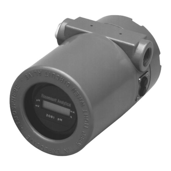
NEMA 7B explosion-proof by Factory Mutual. local calibration and range adjustment. The standard LCD display menu indicates the pH value as well as The Rosemount logo, HART and SMART Family are registered trademarks of temperature, current output value, range values, Rosemount Inc. -
Page 31: Functional Specifications
Class I, Div. 1, Groups B, C & D two-wire, 18 AWG, shielded, Belden 8760 or Class II, Div. 1, Groups E, F, & G equal (Rosemount Analytical PN 9200001). Class III, Div. 1 CSA: Class I, Div. 1, Groups C& D Weight/Shipping Weight: 2.18 kg/2.68 kg (4.8 lb/5.9 lb) -
Page 32: Recommended Sensors
Model GP1 Disposable 9.6 ORDERING INFORMATION Model 2081 pH Two-Wire Transmitter is housed in a NEMA 4X (IP65) weatherproof, corrosion-resistant enclo- sure suitable for pipe mounting. Standard features include LCD digital display, automatic temperature compensa- tion, and isolated 4-20 mA output with HART digital communications capability. External DC loop power is required from a distributed control system or Model 515 isolated power supply. -
Page 33: Model 2081 Ph Replacement Parts And Accessories
MODEL 2081 pH SECTION 9.0 DESCRIPTION AND SPECIFICATIONS 9.7 MODEL 2081 PH REPLACEMENT PARTS AND ACCESSORIES DESCRIPTION RECOMMENDED SPARES 23419-00 PCB, 2081 LCD Display (Requires pH overlay P/N 9240008-00) 23420-01 PCB, 2081 Interface 23421-04 PCB Electronics Stack with LCD Display (factory calibrated) -
Page 34: Return Of Materials
Call 1-949-863-1181 for a Retur n Call Rosemount Analytical for authorization. Materials Authorization (RMA) number. Supply the purchase order number, and make 10.2 WARRANTY REPAIR. - Page 35 The Rosemount customer sales and service organization comprises a network of fully equipped support centers strategi- cally located throughout the world. From many of these locations, the Rosemount Group provides support, distribution of finished products, repair facilities, and training for our customers.
- Page 36 FOLD ALONG DOTTED LINES...
- Page 37 For Customer Support Mike Stoessl 24 hours a day/365 days a year, President, Rosemount Analytical-Uniloc Division Call 1-800-854-8257 Complete this registration, fold it in thirds so the return address shows, and drop it in any mailbox, or visit our web- site at www.RAuniloc.com and register on-line to double your standard warranty from 1 year to 2 years.
- Page 38 AND IMPLIED WARRANTIES OF MERCHANTABILITY AND FITNESS FOR A PARTICULAR PURPOSE. RETURN OF MATERIAL Material returned for repair, whether in or out of warranty, should be shipped prepaid to: Rosemount Analytical Inc. Uniloc Division 2400 Barranca Parkway Irvine, CA 92606...
- Page 39 CUSTOMER SUPPORT CENTER 1-800-854-8257 ON-LINE ORDERING NOW AVAILABLE ON OUR WEB SITE http://www.RAuniloc.com Credit Cards for U.S. Purchases Only. Rosemount Analytical Inc. Uniloc Division 2400 Barranca Parkway Irvine, CA 92606 USA Tel: (949) 863-1181 http://www.RAuniloc.com © Rosemount Analytical Inc. 1999...
Need help?
Do you have a question about the 2081 pH and is the answer not in the manual?
Questions and answers