Table of Contents
Advertisement
Quick Links
Quick Installation Guide
00825-0100-4750, Rev BA
June 2009
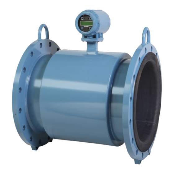
Rosemount 8750WA Magnetic Flowmeter
System (Transmitter and Sensor)
www.rosemount.com
¢00825-0100-4725.¤
Start
Step 1: Pre-Installation
Step 2: Handling
Step 3: Mounting
Step 4: Installation
(Flanged Sensors)
(Wafer Sensors)
Step 5: Grounding
Step 6: Wiring
Step 7: Basic Configuration
End
Rosemount 8750WA
Advertisement
Table of Contents

Related Manuals for Rosemount 8750WA


Summary of Contents for Rosemount 8750WA
- Page 1 Quick Installation Guide 00825-0100-4750, Rev BA Rosemount 8750WA June 2009 Rosemount 8750WA Magnetic Flowmeter System (Transmitter and Sensor) Start Step 1: Pre-Installation Step 2: Handling Step 3: Mounting Step 4: Installation (Flanged Sensors) (Wafer Sensors) Step 5: Grounding Step 6: Wiring Step 7: Basic Configuration www.rosemount.com...
-
Page 2: Important Notice
Quick Installation Guide 00825-0100-4750, Rev BA Rosemount 8750WA June 2009 © 2009 Rosemount Inc. All rights reserved. All marks property of owner. Emerson Process Management Rosemount Inc. 12001 Technology Drive Eden Prairie, MN USA 55344 T (US) (800) 999-9307 T (Intnl) (952) 906-8888... -
Page 3: Step 1: Pre -Installation
LOI screen (see Figure 1). If the Rosemount 8750WA is mounted separately from the sensor, it is not subject to limitations that might apply to the sensor. -
Page 4: Installation Procedures
2. Attach the Rosemount 8750WA transmitter to the mounting bracket using the mounting screws. Identify Options and Configurations The standard application of the 8750WA includes a 4–20 mA output and control of the sensor coils and electrodes. Other applications may require one or more of the following configurations or options: •... - Page 5 Electrical Considerations Before making any electrical connections to the Rosemount 8750WA, consider the local and plant electrical standards and be sure to have the proper power supply, conduit, and other accessories.
- Page 6 PTFE-lined sensors are shipped with end covers that protect it from both mechanical damage and normal unrestrained distortion. Remove the end covers just before installation. Figure 2. Rosemount 8750WA Flanged Sensor Support for Handling 6-Inch and Larger Sensors ½- through 4-Inch Sensors...
- Page 7 5 Pipe Diameters Flow The 8750WA may be installed with as few as zero pipe diameters upstream. Consult the factory for performance in applications with less than ideal straight runs. Sensors can be installed with as few as zero diameters of straight run.
- Page 8 Figure 4. Sensor Orientation FLOW FLOW The electrodes in the Rosemount 8750WA flanged sensor are properly orientated when the two measurement electrodes are in the 3 and 9 o’clock positions, as shown on the right of Figure 4. The electrodes in the Rosemount 8750WA wafer sensor are properly orientated when the top of the sensor is either vertical or horizontal, as shown in Figure 5.
- Page 9 Quick Installation Guide 00825-0100-4750, Rev BA Rosemount 8750WA June 2009 4: I NSTALLATION Flanged Sensors Gaskets The sensor requires a gasket at each of its connections to adjacent devices or piping. The gasket material selected must be compatible with the process fluid and operating conditions. Metallic or spiral-wound gaskets can damage the liner.
-
Page 10: Alignment And Bolting
Alignment and Bolting 1. On 1.5 - through 8-inch (40 through 200 mm) line sizes. Rosemount strongly recommends ordering the centering rings to insure proper centering of the sensor between the process flanges. Place the alignment rings over each end of the sensor. - Page 11 Tighten flange bolts in crosswise sequence. Always check for leaks at the flanges after tightening the flange bolts. All sensors require a second torquing 24 hours after initial flange bolt tightening. Table 3. Rosemount 8750WA Wafer Sensor Torque Specifications Size Code Line Size...
- Page 12 Quick Installation Guide 00825-0100-4750, Rev BA Rosemount 8750WA June 2009 5: G ROUNDING Use Table 4 to determine which process grounding option to follow for proper installation. The sensor case should be earth grounded in accordance with national and local electrical codes.
- Page 13 Quick Installation Guide 00825-0100-4750, Rev BA Rosemount 8750WA June 2009 CONTINUED Figure 9. Grounding with Grounding Rings or Lining Protectors Grounding Rings or Lining Protectors Figure 10. Grounding with Grounding Rings or Lining Protectors Grounding Rings or Lining Protectors...
- Page 14 Quick Installation Guide 00825-0100-4750, Rev BA Rosemount 8750WA June 2009 CONTINUED Figure 11. Grounding with Grounding Electrode...
- Page 15 AC or DC power wiring. • Device must be properly grounded or earthed according to local electric codes. • Rosemount combination cable model number 08712-0752-0001 (ft) or 08712-0752-0003 (m) is required to be used to meet EMC requirements.
-
Page 16: Installation Category
Installation Category The installation category for the 8750WA32 is (Overvoltage) Category II. Overcurrent Protection The Rosemount 8750WA32 Flowmeter Transmitter requires overcurrent protection of the supply lines. Maximum ratings of overcurrent devices are as follows: Table 5. Maximum ratings Power System... - Page 17 Quick Installation Guide 00825-0100-4750, Rev BA Rosemount 8750WA June 2009 CONTINUED Connect 4–20 mA Loop External Power Source The 4–20 mA output loop signal may be powered internally or externally. The default position of the internal/external analog power jumper is in the internal position. The user-selectable power supply jumper is located on the electronics board.
-
Page 18: Supply Wire Requirements
Overcurrent Protection The Rosemount 8712 Flowmeter Transmitter requires overcurrent protection of the supply lines. Maximum ratings of overcurrent devices are as follows: Table 6. Overcurrent Ratings... - Page 19 Quick Installation Guide 00825-0100-4750, Rev BA Rosemount 8750WA June 2009 CONTINUED Connect 4–20 mA Loop External Power Source The 4–20 mA output loop signal may be powered internally or externally. The default position of the internal/external analog power switch is in the internal position. The user-selectable power supply switch is located on the electronics board.
- Page 20 Quick Installation Guide 00825-0100-4750, Rev BA Rosemount 8750WA June 2009 CONTINUED Figure 16. Conduit Preparation Wrong Correct Coil Drive Coil Drive Electrode Electrode Cables Power Cables Power Power Power Outputs Outputs Outputs Outputs...
- Page 21 Quick Installation Guide 00825-0100-4750, Rev BA Rosemount 8750WA June 2009 CONTINUED Table 7. Cable Requirements Description Unit of Measure Part Number Signal Cable (20 AWG) Belden 8762, Alpha 08712-0061-0001 2411 equivalent 08712-0061-0003 Coil Drive Cable (14 AWG) Belden 8720, 08712-0060-0001...
- Page 22 Quick Installation Guide 00825-0100-4750, Rev BA Rosemount 8750WA June 2009 CONTINUED Sensor to Remote Mount Transmitter Connections Figure 17. 8750WA32ES Remote Mount Wiring Diagram Do not connect AC power to the sensor or to terminals 1 and 2 of the transmitter, or...
- Page 23 NOTE Interconnecting cables for integral mount transmitters are wired at the factory. Do not use cable other than that supplied by Emerson Process Management, Rosemount, Inc. Cover Jam Screw (8750WA32ES Only) For transmitter housings shipped with a cover jam screw, the screw should be properly installed once the transmitter has been wired and powered up.
-
Page 24: Step 7: Basic Configuration
Quick Installation Guide 00825-0100-4750, Rev BA Rosemount 8750WA June 2009 CONTINUED Sensor to Remote Mount Transmitter Connections Figure 19. 8750WA12ES Remote Mount Wiring Diagram 7: B ASIC ONFIGURATION Once the magnetic flowmeter is installed and power has been supplied, the transmitter must be configured through the basic setup. - Page 25 Quick Installation Guide 00825-0100-4750, Rev BA Rosemount 8750WA June 2009 CONTINUED Line Size The line size (sensor size) must be set to match the actual sensor connected to the transmitter. The size must be specified in inches. Calibration Number The sensor calibration number is a 16-digit number used to identify sensors calibrated at the Rosemount factory.
- Page 26 Quick Installation Guide 00825-0100-4750, Rev BA Rosemount 8750WA June 2009 Function HART Fast Keys Actual Velocity 1,2,3,1,2,5 Velocity Deviation 1,2,3,1,2,6 Transmitter Calibration Test Result 1,2,3,1,2,7 Sensor Calibration Deviation 1,2,3,1,2,8 Sensor Calibration Test Result 1,2,3,1,2,9 Coil Circuit Test Result 1,2,3,1,2,10 Electrode Circuit Test Result...
- Page 27 Quick Installation Guide 00825-0100-4750, Rev BA Rosemount 8750WA June 2009 Function HART Fast Keys Electrode Circuit Test Result 1,2,4,7,11 Trims 1,2,5 D/A Trim\ 1,2,5,1 Scaled D/A Trim 1,2,5,2 Digital Trim 1,2,5,3 Auto Zero 1,2,5,4 Universal Trim 1,2,5,5 View Status 1,2,6...
- Page 28 Quick Installation Guide 00825-0100-4750, Rev BA Rosemount 8750WA June 2009 Function HART Fast Keys Pulse Scaling 1,4,2,2,1 Pulse Width 1,4,2,2,2 Pulse Mode 1,4,2,2,3 Pulse Output Loop Test 1,4,2,2,4 DI/DO Output 1,4,2,3 Digital Input 1 1,4,2,3,1 Digital Output 2 1,4,2,3,2 Reverse Flow...
-
Page 29: Local Operator Interface
Quick Installation Guide 00825-0100-4750, Rev BA Rosemount 8750WA June 2009 Function HART Fast Keys Manufacturer 1,4,6,1 1,4,6,2 Descriptor 1,4,6,3 Message 1,4,6,4 Date 1,4,6,5 Device ID 1,4,6,6 PV Sensor Serial Number 1,4,6,7 Sensor Tag 1,4,6,8 Write Protect 1,4,6,9 Revision No. 1,4,6,10... - Page 30 Quick Installation Guide 00825-0100-4750, Rev BA Rosemount 8750WA June 2009 Table 10. HART Field Communicator Fast Keys for 8750WA12 Function HART Fast Keys Process Variables (PV) Primary Variable Value 1,1,1 Primary Variable% 1,1,2 PV Loop Current 1,1,3 Totalizer Set-Up 1,1,4...
- Page 31 Quick Installation Guide 00825-0100-4750, Rev BA Rosemount 8750WA June 2009 Function HART Fast Keys Total Limit Hysteresis 1,2,2,8,5 Advanced Diagnostics 1,2,3 8714i Meter Verification 1,2,3,1 Run 8714i 1,2,3,1,1 8714i Results 1,2,3,1,2 Test Condition 1,2,3,1,2,1 Test Criteria 1,2,3,1,2,2 8714i Test Result...
- Page 32 Quick Installation Guide 00825-0100-4750, Rev BA Rosemount 8750WA June 2009 Function HART Fast Keys 8714i results 1,2,4,7 Test Condition 1,2,4,7,1 Test Criteria 1,2,4,7,2 8714i Test Result 1,2,4,7,3 Simulated Velocity 1,2,4,7,4 Actual Velocity 1,2,4,7,5 Velocity Deviation 1,2,4,7,6 Xmtr Cal Test Result...
- Page 33 Quick Installation Guide 00825-0100-4750, Rev BA Rosemount 8750WA June 2009 Function HART Fast Keys Configure Output 1,4,2 Analog Output 1,4,2,1 PV URV 1,4,2,1,1 PV LRV 1,4,2,1,2 PV Loop Current 1,4,2,1,3 PV Alarm Type 1,4,2,1,4 AO Loop Test 1,4,2,1,5 D/A Trim...
- Page 34 Quick Installation Guide 00825-0100-4750, Rev BA Rosemount 8750WA June 2009 Function HART Fast Keys Reverse Total 1,4,2,5,4 Start Totalizer 1,4,2,5,5 Stop Totalizer 1,4,2,5,6 Reset Totalizer 1,4,2,5,7 Alarm Level 1,4,2,6 HART Output 1,4,2,7 Variable Mapping 1,4,2,7,1 TV is 1,4,2,7,1,1 QV is...
- Page 35 1,4,6,11,5 Review (1) Scroll through the menu on the 375 to access this item. Table 11. Electrical Data Rosemount 8750WA32ES Flow Transmitter Power supply: 250 V ac, 1 A or 50 Vdc, 2,5 A, 20 W maximum Pulsed output circuit:...
-
Page 36: Canadian Standards Association (Csa)
Ordinary Location Approval Enclosure Type 4X/IP 66 Division 2 Approval (All transmitters) Reference Rosemount Control Drawing 08732-1052 (8750WA). Class I, Division 2, Groups A, B, C, D Temp Codes – T4 (8750WA12 at 40°C), T4 (8750WA32 at 60°C: -50 °C Ta 60 °C) Dust-ignition proof Class II/III, Division 1, Groups E, F, G Temp Codes –... - Page 37 Quick Installation Guide 00825-0100-4750, Rev BA Rosemount 8750WA June 2009...
- Page 38 Quick Installation Guide 00825-0100-4750, Rev BA Rosemount 8750WA June 2009...
- Page 39 Quick Installation Guide 00825-0100-4750, Rev BA Rosemount 8750WA June 2009...
- Page 40 Quick Installation Guide 00825-0100-4750, Rev BA Rosemount 8750WA June 2009...
Need help?
Do you have a question about the 8750WA and is the answer not in the manual?
Questions and answers