
Related Manuals for Rosemount 2120


Summary of Contents for Rosemount 2120
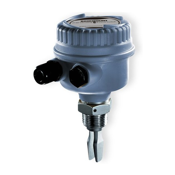
- Page 1 Reference Manual 00809-0100-4030, Rev DA June 2007 Rosemount 2120 Vibrating Fork Liquid Level Switch www.rosemount.com...
- Page 3 Emerson Process Management Sales Representative. CAUTION Rosemount pursues a policy of continuous development and product improvement. The specification in this document may therefore be changed without notice. To the best of our knowledge, the information contained in this document is accurate and Rosemount cannot be held responsible for any errors, omissions or other misinformation contained herein.
-
Page 4: Rev Da Rosemount
Reference Manual 00809-0100-4030, Rev DA Rosemount 2120 June 2007... -
Page 5: Table Of Contents
2120 Intrinsically Safe NAMUR ........ - Page 6 2120 Maintenance........
- Page 7 Reference Manual 00809-0100-4030, Rev DA Rosemount 2120 June 2007 Canadian Standards Association (CSA) Non-Incendive Approval ....B-5 Instructions specific to hazardous (classified locations) area installations..B-5 European Approvals .
- Page 8 Reference Manual 00809-0100-4030, Rev DA Rosemount 2120 June 2007 TOC-4...
- Page 9 Handling the 2120 ........
-
Page 10: Switch Overview
Switch Overview The Rosemount 2120 is a liquid point level switch based on the vibrating short fork technology making it suitable for virtually all liquid applications. Complete range of process connections, wide choice of housing and wetted parts materials, four different switching functions, extended fork lengths, hazardous area and overfill approvals makes it configurable to almost all requirements. -
Page 11: Overfill Protection
Overfill Protection Spillage caused by overfilling can be hazardous to people and the environment, resulting in lost product, and clean up costs. The 2120 is a limit level switch with a built-in visible ‘heartbeat LED’ used to signal overfill at any time. -
Page 12: Application Considerations
• Foam • In almost all cases the 2120 is insensitive to foams (do not see the foam as a liquid). • However in rare occasions some very dense foams may be seen as liquid, known example of this is found in ice-cream and orange juice manufacturing. -
Page 13: Device Identification
Reference Manual 00809-0100-4030, Rev DA Rosemount 2120 June 2007 Device Identification See Appendix B: Product Certifications for specific product approvals. 2120 Vibrating Fork Level Switch www.rosemount.com DIR E C T L OAD S WIT C HING MAGNETIC TEST POINT Supply... -
Page 14: Installation Considerations And Recommendations
• Ensure that the forks do not come into contact with the tank wall or any internal fittings or obstructions. • Avoid installing the 2120 where it will be exposed to liquid entering the tank at the fill point. • Avoid heavy splashing on the forks. - Page 15 Figure 1-4. Example of ok and not ok build-up on tank wall. • Extra consideration is needed if the plant vibration is close to the 1300 Hz operating frequency of the 2120 • Avoid Long Fork Length and Vibration without Supporting the Fork Figure 1-5.
-
Page 16: Switchpoint
Warranty Emerson Process Management will replace a faulty or failed 2120 with a new unit provided that the fault or failure is reported either directly or via an accredited representative, within 1 year from the date of supply, and the product has been installed and used in accordance with Emerson Process Management instruction manual 00809-0100-4030. -
Page 17: Safety Messages
Reference Manual 00809-0100-4030, Rev DA Rosemount 2120 June 2007 ECTION NSTALLATION Safety Messages ..........page 2-1 Mechanical Installation . -
Page 18: Mechanical Installation
Reference Manual Rosemount 2120 00809-0100-4030, Rev DA June 2007 Mechanical Installation Figure 2-1. Sealing Figure 2-2. Tighten the Switch PTFE (Teflon) NPT, BSPT (R) thread Gasket BSPP (G) thread Seal (supplied in Tri-Clamp 02100-1020-0001) Correct Fork Alignment Ensure correct fork alignment. -
Page 19: Pipe Installation
Reference Manual Rosemount 2120 00809-0100-4030, Rev DA June 2007 Pipe Installation Vessel Installation... -
Page 20: Cable Gland Orientation
Reference Manual Rosemount 2120 00809-0100-4030, Rev DA June 2007 Cable Gland Orientation Set Mode Switch / Switching Time Delay Mode Switch/Time Delay PLC/PNP OPERATION MODE Dry On Mode Dry On Wet On Seconds Delay Wet On Mode... - Page 21 Reference Manual Rosemount 2120 00809-0100-4030, Rev DA June 2007 1. Mode switch Dry on or wet on mode selection. 2. Switching time delay 0.3, 1, 3, 10, or 30 seconds time delay selection. Figure 2-3. Mode Dry On, 1 second time delay (typical for high level applications)
-
Page 22: Led Indication
Reference Manual Rosemount 2120 00809-0100-4030, Rev DA June 2007 LED Indication LED Flash Rate Switch Status Continuous Output state is on 1 every second Output state is off 1 every 2 seconds Uncalibrated 1 every 4 seconds Load fault; load current too high; load short circuit... -
Page 23: Electrical Installation
The Rosemount 2120 requires a minimum current of 3mA, which continues to flow when the 2120 is ‘off’. If selecting a relay to wire in series with the 2120, the user must ensure that the drop-out voltage of the relay is greater than the voltage which will be generated across the... - Page 24 Reference Manual Rosemount 2120 00809-0100-4030, Rev DA June 2007 High level Dry = ON Low level Wet = ON Dry On Wet On Dry On Wet On Seconds Delay Seconds Delay <3mA <3mA Fuse Fuse Fuse Fuse 2A(T) 2A(T) 2A(T)
-
Page 25: 2120 Pnp/Plc Version
Reference Manual Rosemount 2120 00809-0100-4030, Rev DA June 2007 2120 PNP/PLC Version • PNP output for load switching and direct PLC switching (3-wire, Yellow label) PLC/PNP OPERATION MODE Dry On Mode Dry On Wet On Wet On Mode Seconds Delay... - Page 26 Reference Manual Rosemount 2120 00809-0100-4030, Rev DA June 2007 High level Dry = ON Low level Wet = ON Dry On Wet On Dry On Wet On Seconds Delay Seconds Delay ΔU ΔU <100μA <100μA <3V <3V ΔU ΔU <3V <3V...
-
Page 27: 2120 Relay Output
DPST = ‘Double Pole, Single Throw’ (on/off) switch - must be fitted for safe disconnection of the power supply. Fit the switch as near to the 2120 as possible. Keep the switch free of obstructions. Label the switch to indicate that it is the supply disconnection device for the 2120. - Page 28 Reference Manual Rosemount 2120 00809-0100-4030, Rev DA June 2007 High level Dry = ON Low level Wet = ON Dry On Wet On Dry On Wet On Seconds Delay Seconds Delay LED on continuously LED flashes every second LED on continuously...
-
Page 29: 2120 Intrinsically Safe Namur
Reference Manual Rosemount 2120 00809-0100-4030, Rev DA June 2007 2120 Intrinsically Safe NAMUR • Intrinsically safe NAMUR (Blue label and cassette) OPERATION MODE Dry On Mode Dry On Wet On Intrinsically Safe EN 50227/ NAMUR Wet On Mode Seconds Delay = 2.2 ... - Page 30 Reference Manual Rosemount 2120 00809-0100-4030, Rev DA June 2007 High level Dry = ON Low level Wet = ON Dry On Wet On Dry On Wet On Seconds Delay Seconds Delay <1.0 mA <1.0 mA >2.2 mA >2.2 mA LED on continuously...
-
Page 31: Magnetic Test Point
2120 Maintenance ........ -
Page 32: Inspection
June 2007 Inspection • Visually examine the 2120 for damage. If it is damaged, do not use. • Ensure the lid and cable glands are fitted securely. • Ensure the LED flash rate is 1 Hz or continually on. If anything else is demonstrated see “LED Indication”... -
Page 33: Troubleshooting
Reference Manual 00809-0100-4030, Rev DA Rosemount 2120 June 2007 Troubleshooting If there is a malfunction, see Table 3-1 for information on possible causes. Table 3-1. Troubleshooting chart. Fault Symptom/Indication Action/Solution Does not switch • No LED; no power • Check the power supply; (check load on direct load switching electronics model) •... -
Page 34: Replacement And Calibration Of Electronic (Pcb) Cassettes
Reference Manual 00809-0100-4030, Rev DA Rosemount 2120 June 2007 Replacement and Calibration of Electronic (PCB) Cassettes When replacing a damage or faulty cassette, it is necessary to calibrate the cassette with the operating frequency of the fork assembly. This is a list of actions required to enable calibration to occur. -
Page 35: To Replace The Cassette, Do The Following
Rosemount 2120 June 2007 To replace the cassette, do the following: 1. Isolate and disconnect the power to the 2120. Insulate ends of the wires. NOTE: On relay units, there may be more than one power source. 2. Remove the screwed-on lid and disconnect the wires, noting connections (Figure 3-1). -
Page 36: Calibration Sequence
Reference Manual 00809-0100-4030, Rev DA Rosemount 2120 June 2007 Calibration Sequence To calibrate the cassette, do the following: 1. Ensure that the sensor forks are dry and the mode switch is set to Wet = On, time delay 1 second. -
Page 37: Appendix A Reference Data
Ordering Information ......... page A-8 Specifications Physical Product Rosemount 2120 Liquid Level Switch Measuring principle Vibrating Fork Applications... -
Page 38: Performance
Reference Manual 00809-0100-4030, Rev DA Rosemount 2120 June 2007 Performance Hysteresis (water) ±0.039-in. (± 1mm) nom. Switching Point (water) 0.5-in. (13 mm) from tip (vertical) / from edge (horizontal) of fork (this will vary with different liquid densities). Functional Maximum Operating Pressure... - Page 39 Reference Manual 00809-0100-4030, Rev DA Rosemount 2120 June 2007 Temperature See Figure A-2. Figure A-2. Temperature 176 (80) 122 (50) 0 (0) -40 (-40) (150) (-40) (60) Process Temperature °F (°C) Liquid Density Minimum 37.5 lb/ft (600 kg/m Liquid Viscosity Range 0.2 to 10,000 cP (centiPoise)
-
Page 40: Electrical
• The relay units are shipped with two PA66 cable glands. Grounding The 2120 should always be grounded either through the terminals or using the external ground connection provided. Electrical Connections • Direct load switching (two-wire) • Solid state PNP output for direct interface to PLC’s (three wire) •... -
Page 41: Dimensional Drawings
Reference Manual 00809-0100-4030, Rev DA Rosemount 2120 June 2007 Dimensional Drawings Threaded Mounting Aluminum/SST Glass Filled Nylon Glass Filled Nylon Cable entry M20x1.5 or / 4 -in NPT 5.60 (142) Cable Gland Cable entry / 4 - or 1.575 (40) A/F M20x1.5 or... -
Page 42: Flange Mounting
Reference Manual 00809-0100-4030, Rev DA Rosemount 2120 June 2007 Flange Mounting Glass filled nylon housing shown. Cable Gland E (M) Note Dimensions are in inches (millimeters) 0.51 (13) 0.51 (13) 1.14 Switchpoint Switchpoint (29) Table A-4. Dimensions are in inches (millimeters) -
Page 43: Hygienic Fitting
Reference Manual 00809-0100-4030, Rev DA Rosemount 2120 June 2007 Hygienic Fitting Glass filled nylon housing shown. 3.52 3.56 3.56 (90) (90) (90) 4.02 (102) 4.02 (102) 4.02 (102) 4.96 (126) 4.96 (126) 1-in. 4.96 Cable BSPP (126) Gland o-ring Cable... -
Page 44: Ordering Information
Reference Manual 00809-0100-4030, Rev DA Rosemount 2120 June 2007 Ordering Information Model Product Description 2120 Vibrating Fork Liquid Level Switch Code Material of Construction: Process Connection/Fork 316L Stainless Steel (1.4404) (1)(2) 316L SST (1.4404) with NACE compliance to MR 0175:2003 (ISO 15156:2003), MR 0103-2003 Halar/PFA, coated 316L SST (1.4404) - Page 45 Reference Manual 00809-0100-4030, Rev DA Rosemount 2120 June 2007 DN80, PN 100 DN100, PN 10/16 DN100, PN 25/40 DN100, PN 64 DN100, PN 100 Other Process Connection Customer Specific Code Electronic Type Available for Certifications Direct load switching (2-wire) 20-264Vac 50/60Hz, 20-60 Vdc...
- Page 46 (5) Other process connections available upon request. (6) Rosemount 2120 IS Namur Vibrating Fork Level Sensor Models 2120***C**I** has demonstrated proven reliability. It is manufactured and supported in a manner suitable for applications up to SIL 2 of IEC 61508 as a Type B Safety Related Subsystem when configured as a high level alarm in conjunction with a Namur Barrier.
-
Page 47: Spare Parts And Accessories
Reference Manual 00809-0100-4030, Rev DA Rosemount 2120 June 2007 Spare Parts and Accessories Part Number Spares and Accessories 02100-1000-0001 Seal for 1-in. BSPP (G1A). Material: Non-asbestos BS7531 grade X carbon fiber with rubber binder 1.54 (39) 1.30 (34) 0.12 (3) 02100-1010-0001 Hygienic adaptor boss 1-in. - Page 48 Reference Manual 00809-0100-4030, Rev DA Rosemount 2120 June 2007 Part Number Spares and Accessories Replacement Cassettes Available for Housing 02120-3000-0001 Direct load switching (2 Wire) (Red) (See page 2-7) A, D, X, S 02120-3010-0001 PNP/PLC cassette (Yellow) (See page 2-9)
-
Page 49: Appendix B Product Certifications
European Directive Information The EC declaration of conformity for all applicable European directives for this product can be found on the Rosemount website at www.rosemount.com. A hard copy may be obtained by contacting your local sales office. ATEX Directive (94/9/EC) Complies with the ATEX Directive. -
Page 50: Ce-Mark
Reference Manual 00809-0100-4030, Rev DA Rosemount 2120 June 2007 CE-mark Complies with applicable directives (EMC, ATEX, LVD) Overfill protection Option available for DIBt/WHG Approved Manufacturing Locations Slough, UK; Chanhassen, USA; and Singapore, Singapore. Hazardous Locations Certifications North American and Canadian Approvals... - Page 51 The metallic alloy used for the enclosure material may be at the accessible surface of this equipment; in the event of rare accidents, ignition sources due to impact and friction sparks could occur. This shall be considered when the 2120 is installed in locations that specifically require Class 1, Div 1 equipment.
- Page 52 OSION PROOF VIBRATING FORK LEVEL SWIT TING FORK LEVEL SWITCH EXPL XPLOSION PR OSION PROOF VIBRA OOF VIBRATING FORK LEVEL SWIT TING FORK LEVEL SWITCH MODEL MODEL No 2120############# No 2120############# SWITCH TYPE ########### SWITCH TYPE ########### SUPPL SUPPLY ############# Y ############# SERIAL SERIAL No.
-
Page 53: Factory Mutual (Fm) Intrinsically Safe Approval
The following instructions apply to equipment covered by FM and CSA Approvals: 1. The Intrinsically Safe approved Rosemount 2120 may be used in hazardous locations with flammable gases and vapors Class 1 Division 1 Groups ABC and D, and Class 1 Zone 0 Group IIC when installed in accordance with control drawing 71097/1154 (Figure B-1 on page B-7), or 71097/1179 (Figure B-2 on page B-8). - Page 54 Rosemount 2120 may generate an ignition-capable level of electrostatic charge. Therefore, when they are used for applications that specifically require group II equipment, the Rosemount 2120 shall not be installed in a location where the external conditions are conducive to the build-up of electrostatic charge on such surfaces.
- Page 55 Reference Manual 00809-0100-4030, Rev DA Rosemount 2120 June 2007 Figure B-1. FM Intrinsically Safe Control Drawing...
- Page 56 Reference Manual 00809-0100-4030, Rev DA Rosemount 2120 June 2007 Figure B-2. CSA Intrinsically Safe Control Drawing...
- Page 57 Reference Manual 00809-0100-4030, Rev DA Rosemount 2120 June 2007 Figure B-3. CSA Non-Incendive Control Drawing...
-
Page 58: European Approvals
The metallic alloy used for the enclosure material may be at the accessible surface of this equipment; in the event of rare accidents, ignition sources due to impact and friction sparks could occur. This shall be considered when the 2120 is being installed in locations that specifically require group II, category 1G equipment. - Page 59 Typical arrangement shown. Sensor specific details omitted. ROSEMOUNT 2120 SEMOUNT 2120 FLAMEPROOF VIBRA OOF VIBRATING FORK LEVEL SWIT TING FORK LEVEL SWITCH FLAMEPR MODEL MODEL No 2120############# No 2120############# SWITCH TYPE ########### SWITCH TYPE ########### SUPPL SUPPLY ############# Y ############# SERIAL SERIAL No.
-
Page 60: Atex Intrinsically Safe Approval
The following instructions apply to equipment covered by certificate number Sira 05ATEX2130X: 1. The 2120 I.S. may be used in a hazardous area with flammable gases and vapors with apparatus groups IIC, IIB and IIA and with temperature classes T1, T2, T3, T4 and T5. - Page 61 2120 may generate an ignition-capable level of electrostatic charge. Therefore, when they are used for applications that specifically require group II, category 1 equipment, the 2120 shall not be installed in a location where the external conditions are conducive to the build-up of electrostatic charge on such surfaces.
-
Page 62: Iecex Flame Proof Approvals
The metallic alloy used for the enclosure material may be at the accessible surface of this equipment; in the event of rare accidents, ignition sources due to impact and friction sparks could occur. This shall be considered when the 2120 is being installed in locations that specifically require zone 0 equipment. -
Page 63: Technical Data
Reference Manual 00809-0100-4030, Rev DA Rosemount 2120 June 2007 10. Technical data: Coding: Zone 0/1 Ex d IIC T6 (Ta = -40°C to + 75°C) Ex d IIC T4 (Ta = -40°C to +125°C) Ex d IIC T3 (Ta = -40°C to +150°C) Ex tD A21 T85°C (Tamb -40°C to +75°C) IP6X... -
Page 64: Iecex Intrinsically Safe Approval
A NAMUR isolating amplifier must be used for intrinsic safety. Instructions specific to hazardous area installations 1. The 2120 I.S. may be used in a hazardous area with flammable gases and vapors with apparatus groups IIC, IIB and IIA and with temperature classes T1, T2, T3, T4 and T5. - Page 65 Reference Manual 00809-0100-4030, Rev DA Rosemount 2120 June 2007 7. Technical Data: Coding: Ex ia IIC T5, Ex iaD 20 T85 (Ta = -40°C to + 80°C) Ex ia IIC T4, Ex iaD 20 T120 (Ta = -40°C to + 115°C) Ex ia IIC T3, Ex iaD 20 T155 (Ta = -40°C to + 150°C)
-
Page 66: National Supervision And Inspection Centre (Nepsi) Approvals
NOTE A NAMUR isolating amplifier must be used for intrinsic safety. 2120 Series Rosemount 2120 Vibrating Fork Liquid Level Switch (hereinafter Level Switch), manufactured by Mobrey Limited, has been certified National Supervision and Inspection Center for Explosion Protection and Safety of Instrumentation (NEPSI). - Page 67 "Code for construction and acceptance of electric device for explosive atmospheres and fire hazard electrical equipment installation engineering". 11. Label and certification plate details. Typical arrangement shown. Sensor specific details omitted. 2120 Vibrating Fork L evel Switch www.rosemount.com NOTE: Certificate No. is GYJ06530 when manufactured in Slough, UK.
- Page 68 Reference Manual 00809-0100-4030, Rev DA Rosemount 2120 June 2007 B-20...
- Page 72 June 2007 Cover Photos: 2120/ 2120 ext plas_rev, 2120_04aa.tif. Rosemount and the Rosemount logotype are registered trademarks of Rosemount Inc. VITON is a registered trademark of E.I. du Pont de Nemours & Co. Hastelloy and Hastelloy C are registered trademarks of Haynes International.
Need help?
Do you have a question about the 2120 and is the answer not in the manual?
Questions and answers