
Related Manuals for Rosemount TankRadar Rex RTG 3920


Summary of Contents for Rosemount TankRadar Rex RTG 3920
- Page 1 Service Manual 308012En, Ed.2 May 2013 Tank Gauging System P r o d u c t D i s c o n t i n u e d www.rosemount-tg.com...
- Page 3 Service manual Second edition Copyright May 2013 © Rosemount Tank Radar AB www.rosemount-tg.com...
- Page 4 Copyright © May 2013 Rosemount Tank Radar AB The contents, descriptions and specifications within this manual is subject to change without notice. Rosemount Tank Radar AB accepts no responsibility for any errors that may appear in this manual. Trademarks Rosemount, and the Rosemount logotype are trademarks of Rosemount Inc.
-
Page 5: Table Of Contents
Service Manual 308012En, Ed.2 Rosemount TankRadar Rex May 2013 Contents Contents ......1-1 YSTEM ESCRIPTION . - Page 6 Service Manual 308012En, Ed.2 Rosemount TankRadar Rex May 2013 Contents REX RTG ..........4-1 4.1.1...
- Page 7 Service Manual 308012En, Ed.2 Rosemount TankRadar Rex May 2013 Contents 5.3.1 Required information ......5-3 5.3.2...
- Page 8 Service Manual 308012En, Ed.2 Rosemount TankRadar Rex May 2013 Contents TOC-4...
-
Page 9: S Ystem D Escription
Service Manual 308012En, Ed.2 Rosemount Tank Radar Rex May 2013 Chapter 1 System Description System Description The TankRadar Rex System is a monitoring and control system for tank level gauging. The system can interface various sensors, such as temperature and pressure sensors, for complete inventory control. -
Page 10: System Description
WinOpi, which in its complete version contains inventory functions. A plant host computer can be connected for further processing of data. All Rosemount Tank Control supplied parts for tank top mounting weigh less than 25 kg (55 lb) (except for pressure flange etc. for the LPG/LNG Gauge). - Page 11 • The TankMaster is a software package for installation and config- uration of level gauging equipment manufactured by Rosemount. The TankMaster program package provides powerful and easy-to- use tools for installation and configuration of level gauging...
- Page 12 Service Manual 308012En, Ed.2 Rosemount Tank Radar Rex May 2013 Chapter 1 System Description...
-
Page 13: Safety
Service Manual 308012En, Ed.2 Rosemount Tank Radar Rex May 2013 Chapter 2 Safety Safety TankRadar Rex equipment is often used in areas where flammable materials are handled and where an explosive atmosphere may be present. To protect both the plant and the staff, precautions must be taken to ensure that this atmosphere cannot be ignited. -
Page 14: Explosion Proof
Units. • Use a certified battery operated instru- ment only. • Use Rosemount original spare parts only. Replacement with non-original spare parts may jeopardize the intrinsic safety. Explosion Proof Explosion proof enclosures can be used when an explosion can be allowed as long as it does not spread outside the enclosure. -
Page 15: Device Description
Service Manual 308012En, Ed.2 Rosemount Tank Radar Rex May 2013 Chapter 3 Device Description Device Description Rex RTG 3.1.1 Overview The Radar Tank Gauge Rex, RTG Rex, is an autonomous distance measuring device. The distance and level calculations are continuously carried out in the Radar Tank Gauge. -
Page 16: Antenna Types
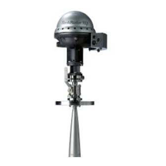
Service Manual 308012En, Ed.2 Rosemount Tank Radar Rex May 2013 Chapter 3 Device Description 3.1.2 Antenna types The Horn Antenna Gauge, RTG 3920 The Horn Antenna Gauge is designed for an 8 in. antenna to be used in small size openings on tanks with fixed roofs. - Page 17 Service Manual 308012En, Ed.2 Rosemount Tank Radar Rex May 2013 Chapter 3 Device Description The Still Pipe Gauge, RTG 3950 The Still Pipe Gauge is used on tanks with still pipes and with all products suited for still pipes. The gauge uses a low-loss radar...
- Page 18 Service Manual 308012En, Ed.2 Rosemount Tank Radar Rex May 2013 Chapter 3 Device Description LPN/LNG Gauge, RTG 3960 The RTG 3960 is designed for level measurement in LPG and LNG tanks. A 4 in. still pipe is used as a wave guide for the measurement.
-
Page 19: Measurement Principle
In combination with Rosemount’s Echofixer, FFT allows measurements in tanks with agitators, mixers and other disturbing objects. Echofixer Rosemount’s Echofixer provides a technique to adapt measurements to various situations, by using information from previous measurements. - Page 20 Fast High Accuracy Signal Technique - FHAST To further improve measurement accuracy, Rex can utilize the benefits of Rosemount’s Fast High Accuracy Signal Technique Multiple Echo Tracking - MET Multiple Echo Tracking is another advanced feature, which provides increased resolution in tanks with disturbing objects. MET facilitates the separation of disturbances from the actual product surface echo.
-
Page 21: Transmitter Head Electronics
Service Manual 308012En, Ed.2 Rosemount Tank Radar Rex May 2013 Chapter 3 Device Description 3.1.4 Transmitter Head Electronics The electronics is mounted in an exchangeable unit in the explosion proof Transmitter Head. A high measurement accuracy is achieved by using digital reference circuitry, and by controlling the internal temperature by an internal heater. - Page 22 Service Manual 308012En, Ed.2 Rosemount Tank Radar Rex May 2013 Chapter 3 Device Description Signal Processing Card (SPC) The SPC is mainly a digital processor card for advanced signal and communication processing as well as handling of auxiliary functions. Analog Processing Card (APC) The APC is used for filtering and multiplexing of analog input signals.
-
Page 23: Write Protection (Metrological Seal)
Service Manual 308012En, Ed.2 Rosemount Tank Radar Rex May 2013 Chapter 3 Device Description 3.1.5 Write protection (Metrological Seal) Part of the memory space in the Electronic Unit is of EEPROM type (Electrically Erasable Programmable Read Only Memory). Program and database updates are possible to perform over the Field Bus without opening the Safety Enclosure. -
Page 24: Internal Calculations
Temperature • Oil/Water interface level Strapping table data downloaded from the Rosemount TankMaster PC software are resident in the gauge. All data is calculated according to updated API and ISO standards. The temperature calculations include API algorithms to handle elements close to the bottom. -
Page 25: Inputs And Outputs
Service Manual 308012En, Ed.2 Rosemount Tank Radar Rex May 2013 Chapter 3 Device Description 3.1.7 Inputs and Outputs Inputs The gauge has: • up to 6 temperature inputs directly into the gauge. • up to 14 temperature inputs to each gauge via separate Data Acquisition Unit. - Page 26 Service Manual 308012En, Ed.2 Rosemount Tank Radar Rex May 2013 Chapter 3 Device Description Technical Data, Analog output Type Analog 4-20 mA current loop, passive or active output (external or internal loop supply) Galvanic isolation >1500 V RMS or DC...
-
Page 27: Database Registers
Service Manual 308012En, Ed.2 Rosemount Tank Radar Rex May 2013 Chapter 3 Device Description 3.1.8 Database Registers Holding Register Holding registers store various transmitter parameters used to control the measurement performance. The database is stored in the non volatile EEPROM memory. It contains tank constants and data controlling the RTG performance. - Page 28 Service Manual 308012En, Ed.2 Rosemount Tank Radar Rex May 2013 Chapter 3 Device Description Input Register Input registers Measured data is continuously stored in the of DAUs, RTGs and FCUs. By viewing the contents of device input registers you can check that the device works properly.
- Page 29 Service Manual 308012En, Ed.2 Rosemount Tank Radar Rex May 2013 Chapter 3 Device Description Minimum level The Minimum Level Distance (C) is defined as the distance (C) distance between the Zero Level (Dipping Datum Point) and Minimum Level of the product surface (tank bottom).
-
Page 30: Tank Geometry
Service Manual 308012En, Ed.2 Rosemount Tank Radar Rex May 2013 Chapter 3 Device Description 3.1.9 Tank Geometry The following parameters are used for tank geometry configuration of a Rex transmitter: Tank Reference Point RTG Ref RTG Reference Distance (G) Point... -
Page 31: 3.1.10 Software Description
Service Manual 308012En, Ed.2 Rosemount Tank Radar Rex May 2013 Chapter 3 Device Description 3.1.10 Software Description The Rex transmitter contains software which controls measurement, communication etc. Each program can be changed by either replacing an EEPROM or by downloading through the TRL/2 bus. Both programs must be changed simultaneously. -
Page 32: Field Communication Unit (Fcu)
Service Manual 308012En, Ed.2 Rosemount Tank Radar Rex May 2013 Chapter 3 Device Description Field Communication Unit (FCU) The Field Communication Unit, FCU acts as a master of communications on the Field Bus and as a slave on the Group Bus. The FCU is an... -
Page 33: Field Bus And Group Bus Communication
Service Manual 308012En, Ed.2 Rosemount Tank Radar Rex May 2013 Chapter 3 Device Description 3.2.1 Field Bus and Group Bus Communication The Field Communication Unit has six communication ports, X1 to X6. TCM interface boards The standard configuration is six with four TRL/2 Field Bus (FB) ports and two TRL/2 Group Bus (GB) ports. -
Page 34: Software
Service Manual 308012En, Ed.2 Rosemount Tank Radar Rex May 2013 Chapter 3 Device Description 3.2.3 Software The FCU software controls the collection of data from the units connected to the Field Bus, and handles the distribution of data to the TankMaster PC on the Group Bus. -
Page 35: Connection To A Pc
Service Manual 308012En, Ed.2 Rosemount Tank Radar Rex May 2013 Chapter 3 Device Description 3.2.5 Connection to a PC The FCU can be connected to the PC either directly via a TRL/2 Group Bus or via the RS-232C interface. The RS-232C connection can be made with 3 wires from the PC to the Field Communication Unit. -
Page 36: Data Acquisition Unit (Dau)
Service Manual 308012En, Ed.2 Rosemount Tank Radar Rex May 2013 Chapter 3 Device Description Data Acquisition Unit (DAU) 3.3.1 Overview The Data Acquisition Unit, DAU, is a complement to the Radar Tank Gauge. Figure 3-15. The DAU. The DAU is equipped with an interface for temperature measurement. -
Page 37: Electronics
Service Manual 308012En, Ed.2 Rosemount Tank Radar Rex May 2013 Chapter 3 Device Description 3.3.3 Electronics The DAU's main circuit board is called DMB, DAU Minimum Board. In Figure 3-17 the block diagram of the DAU is shown. (power supply for DAU) Figure 3-17. -
Page 38: Temperature Measurement
Service Manual 308012En, Ed.2 Rosemount Tank Radar Rex May 2013 Chapter 3 Device Description 3.3.4 Temperature Measurement Temperature sensors Measuring the product temperature is necessary for correct inventory calculations. Up to 14 temperature sensors can be connected to each Data Acquisition Unit. The temperature elements are placed in a tube which is anchored to the bottom of the tank. -
Page 39: Rtd Multiplexer
Service Manual 308012En, Ed.2 Rosemount Tank Radar Rex May 2013 Chapter 3 Device Description 3.3.5 RTD Multiplexer There is an RTD multiplexer for the multiplexing of signals from the Resistance Temperature Detectors (RTDs). See Figure 3-18. Channel 0 is connected to a 100 W precision reference resistor (0.01% accuracy) located on the DMB. -
Page 40: Dau Software
Service Manual 308012En, Ed.2 Rosemount Tank Radar Rex May 2013 Chapter 3 Device Description 3.3.6 DAU Software The software in the DAU operates in the context shown in Figure 3-19. The software is made up of various modules called tasks. The tasks are... -
Page 41: Database Registers
Service Manual 308012En, Ed.2 Rosemount Tank Radar Rex May 2013 Chapter 3 Device Description 3.3.7 Database Registers The DAU’s database is stored in a nonvolatile memory (it will retain its contents even if the power is turned off), a serial EEPROM. The database is copied to a part of RAM that acts as a Shadow RAM in order to increase performance when accessing the database. -
Page 42: Level Value Pick-Up
Service Manual 308012En, Ed.2 Rosemount Tank Radar Rex May 2013 Chapter 3 Device Description 3.3.9 Level value pick-up There are several DAU functions which require level data from the associated RTG: • The optional DAU local display can show tank level measured by the associated RTG. -
Page 43: 3.3.10 Automatic Test Of Temperature References
Database registers 307-310. Remote Display Unit 40 (RDU 40) The RDU 40 is a display unit for use with Rosemount TankRadar Rex and Rosemount TankRadar Pro. The display functions are controlled by the software of the connected TankRadar gauge. - Page 44 Service Manual 308012En, Ed.2 Rosemount Tank Radar Rex May 2013 Chapter 3 Device Description 3-30...
-
Page 45: Rex Rtg
Service Manual 308012En, Ed.2 Rosemount Tank Radar Rex May 2013 Chapter 4 Service Service Rex RTG 4.1.1 How to initiate an echo search There are several ways that an echo search can be initiated: • Switch power supply off and on. A search is automatically per- formed. -
Page 46: Viewing And Editing Database Registers
Service Manual 308012En, Ed.2 Rosemount Tank Radar Rex May 2013 Chapter 4 Service 4.1.2 Viewing and Editing database registers Measured data is continuously stored in the Input registers of DAUs, RTGs and FCUs. By viewing the contents of device input registers you can check that the device works properly. -
Page 47: Loading And Saving A Device Database
Service Manual 308012En, Ed.2 Rosemount Tank Radar Rex May 2013 Chapter 4 Service 4.1.3 Loading and Saving a device database Each device (RTG, DAU and FCU) is equipped with a database of parameters used by the Application Software to control the performance of the device. -
Page 48: Loading The Default Database
Service Manual 308012En, Ed.2 Rosemount Tank Radar Rex May 2013 Chapter 4 Service 4.1.4 Loading the default database The Default Database is the original factory setting for the RTG Database. TankMaster WinSetup offers the option to load the Default Database. -
Page 49: Installing New Transmitter Software
Service Manual 308012En, Ed.2 Rosemount Tank Radar Rex May 2013 Chapter 4 Service 4.1.5 Installing new Transmitter Software The transmitter software is stored in flash EEPROM. The software consists of boot software and application software. They are both placed in the same EEPROM. - Page 50 Service Manual 308012En, Ed.2 Rosemount Tank Radar Rex May 2013 Chapter 4 Service Click the Browse button and locate the flash program file. Use xxxB.cry file for Boot Software and xxxA.cry file for Application Software. Always start by downloading the Boot Software.
- Page 51 Service Manual 308012En, Ed.2 Rosemount Tank Radar Rex May 2013 Chapter 4 Service Changing EEPROM: Note! Make sure that power is turned off Check if there is any screw that is sealed. Contact Rose- mount Tank Gauging before breaking the seal if warranty is still valid.
- Page 52 Service Manual 308012En, Ed.2 Rosemount Tank Radar Rex May 2013 Chapter 4 Service Remove the old EEPROM by using the IC Extractor tool. Do not use a screwdriver or simi- lar tools. Place the new EEPROM into the socket. Make sure that the...
- Page 53 Service Manual 308012En, Ed.2 Rosemount Tank Radar Rex May 2013 Chapter 4 Service Check the Software version in TankMaster WinSetup: Select the desired device icon in the workspace window. Click the right mouse button and choose the Properties option. Choose the Communication tab. Now the transmitter software version is displayed in the Version field.
-
Page 54: Exchanging The Transmitter Head Electronics
Service Manual 308012En, Ed.2 Rosemount Tank Radar Rex May 2013 Chapter 4 Service 4.1.6 Exchanging the Transmitter Head Electronics Note! Make sure that power is turned off Removing the THE Check if there is any screw that is sealed. Contact Rosemount Tank Gauging before breaking the seal if warranty is still valid. - Page 55 Service Manual 308012En, Ed.2 Rosemount Tank Radar Rex May 2013 Chapter 4 Service Replacing the THE Connect the cables to the THE. See Figure 4-1 below. Press firmly so that the connectors lock into place. Connection to the TIC and TMC board, for further infor- mation see “TIC/TMC Con-...
- Page 56 Service Manual 308012En, Ed.2 Rosemount Tank Radar Rex May 2013 Chapter 4 Service Make sure that the PTFE plugs are clean. Lower the THE. Make sure that the cables are not stuck between the THE and the base of the enclosure. The THE must rest firmly on the base so that there is no gap for the microwaves to bridge.
-
Page 57: Write Protection (Metrological Seal)
Service Manual 308012En, Ed.2 Rosemount Tank Radar Rex May 2013 Chapter 4 Service 4.1.7 Write protection (Metrological Seal) A switch on the FCC board can be used to prevent unauthorized changes in the RTG database. The switch can be sealed in the write- inhibit position by using a special plastic cover. - Page 58 Service Manual 308012En, Ed.2 Rosemount Tank Radar Rex May 2013 Chapter 4 Service Remove the plastic cover and turn the switch to the right. Write Enable Protect Replace the plastic cover and seal the switch in the write protect posi- tion.
-
Page 59: Temperature Measurement
Service Manual 308012En, Ed.2 Rosemount Tank Radar Rex May 2013 Chapter 4 Service 4.1.8 Temperature measurement The Rex transmitter can be connected to 1-3 single spot temperature elements, or to 1-6 multiple spot common return or average elements if the Temperature Multiplexer Card (TMC) is installed. - Page 60 Service Manual 308012En, Ed.2 Rosemount Tank Radar Rex May 2013 Chapter 4 Service TIC/TMC Configuration The TMC board is configured depending on what type of sensor that is used. The jumpers are installed at factory and do normally not need to be changed.
- Page 61 Service Manual 308012En, Ed.2 Rosemount Tank Radar Rex May 2013 Chapter 4 Service Set jumpers on the TMC board to one of the following alternatives: 1-6 multiple spot or average elements 8 pin connector cable Figure 4-3. TMC board configured for 1-6 multiple spot or average ele- ments •...
- Page 62 Service Manual 308012En, Ed.2 Rosemount Tank Radar Rex May 2013 Chapter 4 Service 1-3 spot elements 8 pin connector cable Figure 4-5. TMC board configured for 1-3 spot elements • No jumpers in socket X4 and X5! • Connect the 8-pin connector cable to the X3 connector on the TMC board.
- Page 63 Service Manual 308012En, Ed.2 Rosemount Tank Radar Rex May 2013 Chapter 4 Service Make sure the 10-pin connec- tor is connected to socket X2 on the TIC board. Carefully attach the TMC on the back of the TIC. Replace the TIC/TMC board and the PCB locking.
- Page 64 Service Manual 308012En, Ed.2 Rosemount Tank Radar Rex May 2013 Chapter 4 Service Temperature sensor configuration By using TankMaster WinSetup you can configure the transmitter by specifying sensor type, sensor range and sensor positions. See WinSetup Reference Manual for further information on how to configure the temperature sensors.
-
Page 65: Analog Inputs
Service Manual 308012En, Ed.2 Rosemount Tank Radar Rex May 2013 Chapter 4 Service 4.1.9 Analog inputs Rex supports two high precision 4-20 mA analog inputs. Using the analog inputs requires that the transmitter is equipped with the Transmitter Interface Card (TIC). - Page 66 Service Manual 308012En, Ed.2 Rosemount Tank Radar Rex May 2013 Chapter 4 Service Software configuration - Analog inputs To configure the analog input signals, do the following: Select the desired Rex transmitter icon in the TankMaster WinSetup workspace. Click the right mouse button and choose the Properties option, select the Configuration tab and click the appropriate Analog Input button.
- Page 67 Service Manual 308012En, Ed.2 Rosemount Tank Radar Rex May 2013 Chapter 4 Service Status information If the input values are incorrect or are not shown in TankMaster check the following: • Analog Input Configuration, see “Software configuration - Analog inputs” on page 4-22.
-
Page 68: 4.1.10 Analog Outputs
Service Manual 308012En, Ed.2 Rosemount Tank Radar Rex May 2013 Chapter 4 Service 4.1.10 Analog outputs Note! The Multi Field Communication Card, version 9150072-673 or later is required. Rex supports one analog output signal. The analog output replaces the second relay output. In this case the Relay 2 cabling is disconnected from the Relay Output Card (ROC) and connected to the MotherBoard. - Page 69 Service Manual 308012En, Ed.2 Rosemount Tank Radar Rex May 2013 Chapter 4 Service FCC Configuration of Analog Output In order to use the Analog Output function the cabling must be disconnected from the ROC board and connected to the Mother Board.
- Page 70 Service Manual 308012En, Ed.2 Rosemount Tank Radar Rex May 2013 Chapter 4 Service Carefully lift the Elec- tronic Unit. Handle the Electronic Unit care- fully. Be especially careful with the PTFE plug at the center of the bottom of the Elec- tronic Unit.
- Page 71 Service Manual 308012En, Ed.2 Rosemount Tank Radar Rex May 2013 Chapter 4 Service Tighten the two screws which hold the Electronic Unit. Remove the PCB locking from the Elec- tronic Unit and remove the FCC board. PCB locking 4-27...
- Page 72 Service Manual 308012En, Ed.2 Rosemount Tank Radar Rex May 2013 Chapter 4 Service Check that the Multi FCC card 9150072-673 is used. Set the jumpers according to Figure 4-9 below for current loop active or passive. Active Passive Figure 4-9. Current Loop Output settings.
- Page 73 Service Manual 308012En, Ed.2 Rosemount Tank Radar Rex May 2013 Chapter 4 Service Software configuration - Analog outputs You can choose various sources for the Analog Output. The Upper Range value for the analog output signal is 20mA and the Lower Range value is 4 mA.
- Page 74 Service Manual 308012En, Ed.2 Rosemount Tank Radar Rex May 2013 Chapter 4 Service Choose a measuring variable in the AOut Source list. Set the Upper and Lower Range for the analog output signal in the Range Values input field. For measuring variables that can not be edited in the Range Value input field, set the Upper and Lower values in Holding Registers 2144 and 2146.
- Page 75 Service Manual 308012En, Ed.2 Rosemount Tank Radar Rex May 2013 Chapter 4 Service Alarm mode settings Level Upper Product level Lower Time Analog Output Alarm mode 20 mA Low Current 4 mA 3.8 mA Time Analog Output 22 mA Alarm mode...
- Page 76 Service Manual 308012En, Ed.2 Rosemount Tank Radar Rex May 2013 Chapter 4 Service Following alarm modes are supported in Rex: Table 4-1: Alarm Modes Alarm Mode Current Output Low Alarm 3.8 mA High Alarm 22.2 mA Freeze The current that was output the last valid measurement...
-
Page 77: 4.1.11 Hart Input
Service Manual 308012En, Ed.2 Rosemount Tank Radar Rex May 2013 Chapter 4 Service 4.1.11 HART Input Hart Slaves are connected to Analog input 1. Connection to HART devices requires a Multi Field Communication Card equipped with optional HART modem. 250 ... - Page 78 Service Manual 308012En, Ed.2 Rosemount Tank Radar Rex May 2013 Chapter 4 Service Software configuration - HART devices Select the desired Rex device icon in the WinSetup workspace window. Click the right mouse button and choose the Properties option. Select the Configuration tab.
-
Page 79: 4.1.12 Relay Output
Service Manual 308012En, Ed.2 Rosemount Tank Radar Rex May 2013 Chapter 4 Service 4.1.12 Relay Output You can use two relay ports if the optional Relay Output Card (ROC) is installed. Different transmitter variables can be chosen to trigger the relay to change state. - Page 80 Service Manual 308012En, Ed.2 Rosemount Tank Radar Rex May 2013 Chapter 4 Service Normally Open/Closed refers to the contact position when a relay is deenergized. This is also referred to as the Alarm state. The terminology can be summarized as follows:...
- Page 81 Service Manual 308012En, Ed.2 Rosemount Tank Radar Rex May 2013 Chapter 4 Service Software configuration - Relay Outputs Select the desired device icon in the WinSetup workspace window. Click the right mouse button, choose the Properties option and select the Configuration tab.
- Page 82 Service Manual 308012En, Ed.2 Rosemount Tank Radar Rex May 2013 Chapter 4 Service Relay states. Alarm In this state the relay is deenergized. Normal In this state the relay is energized. Toggle The relay switches periodically between Normal and Alarm.
- Page 83 Service Manual 308012En, Ed.2 Rosemount Tank Radar Rex May 2013 Chapter 4 Service Relay Functions You can use one or two set points for relays connected to the Rex transmitter. Consequently, there are two or three zones in which different relay states can be specified.
- Page 84 Service Manual 308012En, Ed.2 Rosemount Tank Radar Rex May 2013 Chapter 4 Service Manual relay control To manually switch between different relay states do the following: Select a Rex gauge in the workspace window. Click the right mouse button and choose the Manual Control Relay...
-
Page 85: Fcu
Service Manual 308012En, Ed.2 Rosemount Tank Radar Rex May 2013 Chapter 4 Service 4.2.1 Default database loading The default database can be loaded by moving the jumpers on terminals X14 and X15. The position of X14 and X15 on the FCU board is shown in Figure 4-13. - Page 86 Service Manual 308012En, Ed.2 Rosemount Tank Radar Rex May 2013 Chapter 4 Service To load the default FCU database: Disconnect power. Move jumpers on socket 14 and 15 to the “upper” position. Connect power. Wait until watchdog lights up, see Figure 4-13.
-
Page 87: Group And Field Bus Ports
Service Manual 308012En, Ed.2 Rosemount Tank Radar Rex May 2013 Chapter 4 Service 4.2.2 Group and Field Bus Ports Inside the FCU box there are two terminals, X10 and X11, which are used for RS-232C Group Bus communication, see Figure 4-14. -
Page 88: Power Supply
Service Manual 308012En, Ed.2 Rosemount Tank Radar Rex May 2013 Chapter 4 Service 4.2.3 Power Supply Power supply can be selected as either 115 V or 230 V with a switch. See Figure 4-16. If the switch is set to 115 V, the box on the label of the FCU must be marked. -
Page 89: Write Protection And Reset
Service Manual 308012En, Ed.2 Rosemount Tank Radar Rex May 2013 Chapter 4 Service 4.2.5 Write protection and Reset There is a write protection switch in the FCU which is used to prevent unauthorized changes to the data in the EPROM. The switch can be locked in the write inhibit position by securing a locking plate with a wire through the clevis pins, see Figure 4-18. -
Page 90: Electronics
Service Manual 308012En, Ed.2 Rosemount Tank Radar Rex May 2013 Chapter 4 Service 4.2.6 Electronics The main board of the Field Communication Unit is the FCP-board (Field Communication Processor). See Figure 4-19 and Figure 4-21. There are a number of LEDs on the FCP board. There are green LEDs for incoming signals and yellow LEDs for outgoing signals. - Page 91 Service Manual 308012En, Ed.2 Rosemount Tank Radar Rex May 2013 Chapter 4 Service The location of the Field bus and Group bus connections are shown in Figure 4-20. Figure 4-20. The location of Field and Group bus connections on the FCP board.
- Page 92 Service Manual 308012En, Ed.2 Rosemount Tank Radar Rex May 2013 Chapter 4 Service Group Bus Interface 1 Power supply TRL/2 + 5 V Filter Switch + 12 V Mains - 12 V input RS-232 Interface 1 Serial Communications Controller Processor...
-
Page 93: Redundancy (Option)
Service Manual 308012En, Ed.2 Rosemount Tank Radar Rex May 2013 Chapter 4 Service 4.2.7 Redundancy (option) Introduction In order to reduce the risk of communication failure between the TankMaster and the units connected to the TRL/2 field bus, two FCUs can be connected to run in parallel. - Page 94 Service Manual 308012En, Ed.2 Rosemount Tank Radar Rex May 2013 Chapter 4 Service Hardware installation • Connect the special three-wire cable between the RS-232 ports of the FCUs. The cable shall be connected to the RS-232 port 2 con- tact.
- Page 95 Service Manual 308012En, Ed.2 Rosemount Tank Radar Rex May 2013 Chapter 4 Service Software configuration Note! For further information on how to configure/install the FCU see TankMaster WinSetup Reference Manual. Power down both FCUs. Power up one of the FCUs.
- Page 96 Service Manual 308012En, Ed.2 Rosemount Tank Radar Rex May 2013 Chapter 4 Service Power up the second FCU. Set the second FCU address. It is important that both FCUs are using the same address. Select the FCU icon in the WinSetup workspace window, click the right mouse button and choose the Properties option.
- Page 97 Service Manual 308012En, Ed.2 Rosemount Tank Radar Rex May 2013 Chapter 4 Service Check the diagnostics Input Register (Input Register 30689) to verify that the "primary" FCU is active. This is indicated by status bit 12=0. (If the "backup" FCU is active status bit 12=1).
-
Page 98: Dau
Service Manual 308012En, Ed.2 Rosemount Tank Radar Rex May 2013 Chapter 4 Service 4.3.1 Setting the temperature measurement range Do the following to set the measuring range of the temperature sensors: Connect the reference resistor corresponding to the desired measure- ment range to channel 15. - Page 99 Service Manual 308012En, Ed.2 Rosemount Tank Radar Rex May 2013 Chapter 4 Service Table 4-3: Temperature Range Temperature Reference Range Resistor () Pt 100 / Cu 90 -50 - +125 °C OPEN OPEN CLOSED 138.50 -50 - +300 °C CLOSED...
-
Page 100: Checking The Resistance Temperature Detectors
Service Manual 308012En, Ed.2 Rosemount Tank Radar Rex May 2013 Chapter 4 Service 4.3.2 Checking the Resistance Temperature Detectors Pt100 sensors (spot measurement) are connected with three wires each. The Cu90 sensors (average measurement) are connected with a common ground. -
Page 101: Exchanging The External Reference Resistor
Service Manual 308012En, Ed.2 Rosemount Tank Radar Rex May 2013 Chapter 4 Service 4.3.3 Exchanging the External Reference Resistor The external reference resistor must be changed if a different temperature measurement range will be used, see 4.3.1. Also, if the local display shows a reference resistor calibration error, it may be necessary to replace it. -
Page 102: Suppressing Error Indication
Service Manual 308012En, Ed.2 Rosemount Tank Radar Rex May 2013 Chapter 4 Service 4.3.4 Suppressing error indication..when associated RTG is not present. Normally a DAU receives queries from the bus master (FCU), and picks up level data from the associated RTG. However, there may be situations when a DAU is installed without bus master and/or RTG. -
Page 103: Write Protection
Service Manual 308012En, Ed.2 Rosemount Tank Radar Rex May 2013 Chapter 4 Service 4.3.6 Write Protection There is a write protection switch to prevent unauthorized changes in the EEPROM. The switch can be sealed in the write inhibit position using a wire through the clevis pins. -
Page 104: Default Database Reload
Service Manual 308012En, Ed.2 Rosemount Tank Radar Rex May 2013 Chapter 4 Service 4.3.7 Default database reload Disconnect the DAU power supply. Remove the program EEPROM from the socket, see Figure 4-31. EEPROM Figure 4-31. Database loader Insert the DB-loader EEPROM into the EEPROM socket. -
Page 105: Local Display Modes
Service Manual 308012En, Ed.2 Rosemount Tank Radar Rex May 2013 Chapter 4 Service 4.3.8 Local Display modes The display has three different display modes. These modes can be changed in two ways: • Press the push button and wait for at least one second. - Page 106 Service Manual 308012En, Ed.2 Rosemount Tank Radar Rex May 2013 Chapter 4 Service Display mode 0: The following values are shown. Only the values for which the DAU has been configured, are shown. The sequence is repeated continuously. Level. L for metric: decimal, colons for feet: inches: inches/17.
- Page 107 Service Manual 308012En, Ed.2 Rosemount Tank Radar Rex May 2013 Chapter 4 Service Display mode 1: The following sequence is shown when the display is in mode 1. Level See display mode 0 for explanation. Temperature sensor 1. If the sensor is below the surface.
- Page 108 You can set this display mode remotely via database register 300. The default reading is level. If you want to remotely change the display to other variables in display mode 2, please contact Emerson Process Management/Rosemount Tank Gauging for instructions. 4-64...
-
Page 109: Local Display Error Codes
Service Manual 308012En, Ed.2 Rosemount Tank Radar Rex May 2013 Chapter 4 Service 4.3.9 Local Display Error codes The type of errors displayed on the local display can be divided into the following groups. • System • External serial communication •... -
Page 110: 4.3.10 Time-Out Settings
Service Manual 308012En, Ed.2 Rosemount Tank Radar Rex May 2013 Chapter 4 Service 4.3.10 Time-out settings Master communication time-out The master communication time-out specifies the elapsed time without contact before communication with the master is considered to be lost. This value is stored in database register 188. The default value is set to 20 s. -
Page 111: Fbm
Service Manual 308012En, Ed.2 Rosemount Tank Radar Rex May 2013 Chapter 4 Service The Field Bus Modem acts as a converter between USB or RS-232C and the TRL/2 Bus. The TRL/2 protocol is used for communication with Rosemount Tank Gauging equipment. -
Page 112: Fbm Instead Of Fcu For Small Systems
Service Manual 308012En, Ed.2 Rosemount Tank Radar Rex May 2013 Chapter 4 Service 4.4.3 FBM instead of FCU for small systems In a small system with a maximum of 16 units (RTGs or DAUs), the Field Bus Modem can be used instead of an FCU. The Field Bus Modem can then be connected directly between the TankMaster PC (master) and the RTGs and the DAUs. -
Page 113: Rdu40
Service Manual 308012En, Ed.2 Rosemount Tank Radar Rex May 2013 Chapter 4 Service RDU 40 4.5.1 Installation To access the upper screw of the RDU 40 cover remove the rubber plug. Unscrew and remove all six screws. Remove the cover and take care of the locking device for the weather protection hatch. - Page 114 Service Manual 308012En, Ed.2 Rosemount Tank Radar Rex May 2013 Chapter 4 Service In order to allow proper operation and to fulfil EMC requirements, the cable between the RDU 40 and the Rex junction box should meet the following requirements: •...
-
Page 115: Two Rdu 40 Connected To The Same Rex
Service Manual 308012En, Ed.2 Rosemount Tank Radar Rex May 2013 Chapter 4 Service 4.5.2 Two RDU 40 connected to the same Rex If two RDU 40 are connected to the same Rex, one of them has to be configured as “slave” while the other is “master”. The slave cannot be configured or controlled individually but follows the master. - Page 116 Service Manual 308012En, Ed.2 Rosemount Tank Radar Rex May 2013 Chapter 4 Service 4-72...
-
Page 117: Calibration
Service Manual 308012En, Ed.2 Rosemount Tank Radar Rex May 2013 Chapter 5 Calibration Calibration Introduction Normally a minor adjustment of the Calibration Distance is needed in order to achieve agreement between measured and actual product level. (For TRL/2 transmitters the Tank Connection Length (TCL) is adjusted). - Page 118 Service Manual 308012En, Ed.2 Rosemount Tank Radar Rex May 2013 Chapter 5 Calibration To change the Calibration Distance value stored in the transmitter database: Start the TankMaster WinSetup program. Select the transmitter icon in the WinSetup workspace. Click the right mouse-button and choose the Properties option.
-
Page 119: Using The Winsetup Calibrate Function
Service Manual 308012En, Ed.2 Rosemount Tank Radar Rex May 2013 Chapter 5 Calibration Using the WinSetup Calibrate function The Calibration function is a tool to adjust the RTG in order to minimize the offset between actual (hand dipped) product levels and the corresponding values measured by the transmitter. -
Page 120: Hand Dipping
Service Manual 308012En, Ed.2 Rosemount Tank Radar Rex May 2013 Chapter 5 Calibration 5.3.2 Hand dipping Staff Only one person should perform the manual ullage measurements in order to guarantee good repeatability between measurements. Hand dip tape Use only one tape for the calibration. The tape should be made of steel and calibrated by an approved testing institute. -
Page 121: Entering Calibration Data
Service Manual 308012En, Ed.2 Rosemount Tank Radar Rex May 2013 Chapter 5 Calibration 5.3.3 Entering calibration data Select the transmitter to be calibrated in the workspace window and choose Calibrate from the Service/Devices menu, - or - click the right mouse button and choose Calibrate. - Page 122 Service Manual 308012En, Ed.2 Rosemount Tank Radar Rex May 2013 Chapter 5 Calibration Click the Refresh button. Now WinSetup calculates the deviations between hand dipped and measured levels. Click the Save Calibration Data in PC Database button in order to save the entered values and return to the Calibration window.
- Page 123 Click the Write new calibration data to RTG button in order to save the current calibration data. Note! By clicking the Write new calibration data to RTG button, the Rosemount Level values in the Calibration Data window are recalculated and the old Calibration Data is replaced.
- Page 124 Service Manual 308012En, Ed.2 Rosemount Tank Radar Rex May 2013 Chapter 5 Calibration...
-
Page 125: Troubleshooting
Service Manual 308012En, Ed.2 Rosemount Tank Radar Rex May 2013 Chapter 6 Troubleshooting Troubleshooting SYMPTOM CAUSE ACTION No contact with Faulty TRL/2 bus connection. Check TRL/2 bus wires. Incorrect address or Unit ID. Check and correct address and Unit ID in TankMaster. - Page 126 Service Manual 308012En, Ed.2 Rosemount Tank Radar Rex May 2013 Chapter 6 Troubleshooting SYMPTOM CAUSE ACTION Not possible to Metrological Seal in Write inhibit Put switch in write enable position. write to RTG position. Temperature Temperature sensor incorrectly Measure resistance on tempera- measurement connected.
- Page 127 Service Manual 308012En, Ed.2 Rosemount Tank Radar Rex May 2013 Chapter 6 Troubleshooting SYMPTOM CAUSE ACTION Echo amplitude below noise Check signal amplitude. threshold. Check for foam on product sur- face. Check inclination of RTG, see “Installation Manual”. Clean antenna.
- Page 128 Service Manual 308012En, Ed.2 Rosemount Tank Radar Rex May 2013 Chapter 6 Troubleshooting SYMPTOM CAUSE ACTION Current input read- Connected device faulty. Check device. incorrect Power supply faulty. Connect a resistance and check the measured value. Measure current. If there is more than one current input then the power supply is multiplexed.
- Page 129 Service Manual 308012En, Ed.2 Rosemount Tank Radar Rex May 2013 Chapter 6 Troubleshooting DAU Display CAUSE ACTION System: No action required 0 - No detected error System: Restart the DAU. 1 - EEPROM (program) error Exchange the EEPROM. System: Restart the DAU.
- Page 130 Service Manual 308012En, Ed.2 Rosemount Tank Radar Rex May 2013 Chapter 6 Troubleshooting DAU Display CAUSE ACTION Internal serial communication No action required. error: 0 - No detected error Internal serial communication Restart the DAU. Exchange error: PCB: DMB for Slave DAU or 1- Error detected DXB for Independent DAU.
- Page 131 Service Manual 308012En, Ed.2 Rosemount Tank Radar Rex May 2013 Chapter 6 Troubleshooting DAU Display CAUSE ACTION Current input error (p for pres- Exchange PCB: DMB for Slave sure): DAU or DXB for Independent 2 - Internal calibration error DAU.
- Page 132 Service Manual 308012En, Ed.2 Rosemount Tank Radar Rex May 2013 Chapter 6 Troubleshooting...
-
Page 133: Spare Parts
Service Manual 308012En, Ed.2 Rosemount Tank Radar Rex May 2013 Chapter 7 Spare Parts Spare Parts Radar Tank Gauge Transmitter Interface Card, TIC 9150072-551 Temperature Multiplexing Card, TMC 9150072-561 Relay Output Card, ROC 9150072-591 Data Acquisition Unit, DAU DAU - DMB board... - Page 134 Service Manual 308012En, Ed.2 Rosemount Tank Radar Rex May 2013 Chapter 7 Spare Parts...
-
Page 135: List Of Drawings
Reflector kit LPG still pipe (Alt. B) 9150 072-924 Reflector kit LPG still pipe (Alt. A) 9150 072-925 Recommended still pipes for Rosemount Radar 9240 003-987 Installation Drawing FBM 2180 sheet 3 DIN-rail 9150 070-972 Installation Drawing FBM 2180 sheet 4 wall mounting... - Page 136 Service Manual 308012En, Ed.2 Rosemount Tank Radar Rex May 2013 Chapter 8 List of Drawings RDU/DAU and Analog Input RTG (W12/X12) 9150 072-940 Temp sensor connection RTG (W12/X12) 9150 072-941 WBS + temperature connection RTG (W12/X12) 9150 072-943 Installation Drawing FBM 2180 sheet 2 USB...
-
Page 137: Technical Data
Service Manual 308012En, Ed.2 Rosemount Tank Radar Rex May 2013 Chapter 9 Technical Data Technical Data RTG 3900 The following specification is valid for RTG 3900 standard version: Ambient operating temperature -40 °C to +70 °C (-40 °F to +158 °F). -
Page 138: Rtg 3920
Service Manual 308012En, Ed.2 Rosemount Tank Radar Rex May 2013 Chapter 9 Technical Data RTG 3920 Instrument accuracy RTG 3900 ± 0.5 mm ± (5/256 in.) RTG 3900 L ± 3 mm ± (1/8 in.). Operating temperature in Max. +230 °C (+445 °F) -
Page 139: Rtg 3930
Service Manual 308012En, Ed.2 Rosemount Tank Radar Rex May 2013 Chapter 9 Technical Data RTG 3930 Instrument accuracy RTG 3900 ± 0.5 mm ± (5/256 in.) RTG 3900 L ± 3 mm ± (1/8 in.). Operating temperature in Max. +230 °C (+445 °F) -
Page 140: Rtg 3950
Service Manual 308012En, Ed.2 Rosemount Tank Radar Rex May 2013 Chapter 9 Technical Data RTG 3950 Instrument accuracy ±0.5 mm + (5/256 in.) RTG 3950 L ±3 mm ± (1/8 in.) Operating temperature in -40 °C to +120 °C (-40 °F to +248 °F) -
Page 141: Rtg 3960
Service Manual 308012En, Ed.2 Rosemount Tank Radar Rex May 2013 Chapter 9 Technical Data RTG 3960 Instrument accuracy RTG 3900 ± 0.5 mm ± (5/256 in.) RTG 3900 L ± 3 mm ± (1/8 in.). Operating temperature at -55 °C to 90 °C (-67 °F to 194 °F) -
Page 142: Fcu 2160
Service Manual 308012En, Ed.2 Rosemount Tank Radar Rex May 2013 Chapter 9 Technical Data FCU 2160 Ambient operating temperature -40 °C to +70 °C (-40 °F to +158 °F) Power Supply 115 or 230 VAC, +10% to -15%, 50-60 Hz, max. 10 W... -
Page 143: Dau 2100
Service Manual 308012En, Ed.2 Rosemount Tank Radar Rex May 2013 Chapter 9 Technical Data DAU 2100 Ambient operating temperature -40 °C to 65 °C (-40 °F to 149 °F) Sensor elements Pt 100 single or multispot Number of sensor elements Max. -
Page 144: Rdu 40
Service Manual 308012En, Ed.2 Rosemount Tank Radar Rex May 2013 Chapter 9 Technical Data RDU 40 Ambient temperature -20 °C to +70 °C (-4 °F to +158 °F) Hazardous locations II 2 G Ex ib IIC T4 Gb certifications Class I Div I Group A, B, C, D... -
Page 145: Fbm 2180
Service Manual 308012En, Ed.2 Rosemount Tank Radar Rex May 2013 Chapter 9 Technical Data FBM 2180 Power supply (for RS- DC 7-12 V, 50 mA 232) Cable to Host PC RS-232: 3 m (10 ft) USB: 3 m (10 ft) - Page 146 Service Manual 308012En, Ed.2 Rosemount Tank Radar Rex May 2013 Chapter 9 Technical Data 9-10...
- Page 147 Service Manual 308012En, Ed.2 Rosemount Tank Radar Rex May 2013 Index Index Alarm mode settings ..........4-31 Analog Processing Card .
- Page 148 Service Manual 308012En, Ed.2 Rosemount Tank Radar Rex May 2013 Index Electronics ..........3-23, 4-46 Exchanging the Transmitter Head Electronics .
- Page 149 Service Manual 308012En, Ed.2 Rosemount Tank Radar Rex May 2013 Index Internal serial communication error ....... . .4-65 Intrinsic safety .
- Page 150 Service Manual 308012En, Ed.2 Rosemount Tank Radar Rex May 2013 Index Select source ..........4-38 Service DAU .
- Page 151 Service Manual 308012En, Ed.2 Rosemount Tank Radar Rex May 2013 Index RTG 3930 ...........9-3 RTG 3960 .
- Page 152 Service Manual 308012En, Ed.2 Rosemount Tank Radar Rex May 2013 Index...
- Page 154 Emerson Process Management Rosemount Tank Gauging Box 130 45 SE-402 51 Göteborg SWEDEN Tel (International): +46 31 337 00 00 Fax (International): +46 31 25 30 22 E-mail: sales.srt@emersonprocess.com www.rosemount-tg.com Copyright © Rosemount Tank Radar AB. Ref. no: 308012En, Ed.2. May 2013.
Need help?
Do you have a question about the TankRadar Rex RTG 3920 and is the answer not in the manual?
Questions and answers