
Related Manuals for Rosemount 3095FB


Summary of Contents for Rosemount 3095FB
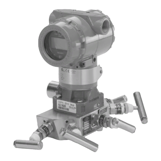
- Page 1 Reference Manual 00809-0100-4738, Rev DA May 2006 Rosemount 3095FB MultiVariable ™ Transmitter ® with Modbus Protocol www.rosemount.com...
- Page 3 For information on Rosemount nuclear-qualified products, contact your local Rosemount Sales Representative. Rosemount 3095FB Multivariable Transmitter with Modbus Protocol may be protected by one or more of the following U.S. Patent Nos. 4,370,890; 4,612,812; 4,791,352; 4,798,089; 4,818,994; 4,833,922; 4,866,435; 4,926,340; 5,028,746; Des. 358,782. MEXICO PATENTADO NO. 154961.
-
Page 5: Table Of Contents
Grounding the Transmitter Case ......2-19 Rosemount 305 Integral Manifold......2-20 Integral Manifold Installation Procedure . - Page 6 Reference Manual 00809-0100-4738, Rev DA Rosemount 3095FB May 2006 Transmitter Menu ........4-15 Maintenance Menu .
-
Page 7: Using This Manual
® and maintenance instructions for the Rosemount 3095FB Multivariable ™ Transmitter with Modbus Protocol and for its operation with the Rosemount 3095FB Configurator User Interface Software. This manual consists of the following chapters: Section 2 Installation • Install the 3095FB •... - Page 8 Reference Manual 00809-0100-4738, Rev DA Rosemount 3095FB May 2006...
-
Page 9: Overview
• Do not attempt to loosen or remove flange bolts while the transmitter is in service. Replacement equipment or spare parts not approved by Rosemount, Inc. for use as spare parts could reduce the pressure retaining capabilities of the transmitter and may render the instrument dangerous. -
Page 10: General Considerations
Reference Manual 00809-0100-4738, Rev DA Rosemount 3095FB May 2006 Improper assembly of manifolds to traditional housing can damage sensor module. • For safe assembly of manifold to traditional flange, bolts must break back plane of flange web (i.e. bolt hold) but must not contact module housing. -
Page 11: Installation Procedures
Reference Manual 00809-0100-4738, Rev DA Rosemount 3095FB May 2006 INSTALLATION Figure 2-1 details the full procedure for installing a new 3095FB. PROCEDURES Figure 2-1. Rosemount 3095FB Installation Flowchart FIELD START INSTALLATION Unpack the Review Installation Rosemount BENCH Considerations CONFIGURE 3095FB... -
Page 12: Review Installation Considerations
Reference Manual 00809-0100-4738, Rev DA Rosemount 3095FB May 2006 Review Installation When choosing an installation location and position, take into account the need for access to the transmitter. For dimensional drawing information see Considerations page A-6. Process Flange Orientation Mount the process flanges with sufficient clearance for process connections. -
Page 13: Mount The Transmitter
2.2 lb (1,0 kg) Mounting Brackets Optional mounting brackets available with the 3095FB facilitate mounting to a panel, wall, or 2-inch pipe. The bracket option for use with the Coplanar flange is 316 SST with 316 SST bolts. Figure 2-3 shows bracket dimensions and mounting configurations for this option. - Page 14 The following guidelines have been established to ensure a tight flange, adapter, or manifold seal. Use only bolts supplied with the transmitter or sold by Rosemount Inc. as a spare part to the Rosemount 3095FB transmitter. The Rosemount 3095FB is shipped with the Coplanar flange installed with four 1.75-inch flange bolts.
- Page 15 Reference Manual 00809-0100-4738, Rev DA Rosemount 3095FB May 2006 Figure 2-3. Optional Mounting Brackets and Mounting Configurations Size Description Qty. in. (mm) Flange bolts 1.75 (44) Flange/adapter bolts 2.88 (73) Manifold/flange bolts 2.25 (57) 1.75 (44) x 4 TRANSMITTER WITH FLANGE BOLTS 2.25 (57) x 4...
- Page 16 Reference Manual 00809-0100-4738, Rev DA Rosemount 3095FB May 2006 Mounting Requirements Refer to figure 2-4 for examples of the following mounting considerations: Liquid Flow Measurement • Place taps to the side of the line to prevent sediment deposits on the transmitter’s process isolators.
-
Page 17: Process Connections
Reference Manual 00809-0100-4738, Rev DA Rosemount 3095FB May 2006 Figure 2-4. Example Installations STEAM SERVICE Flow Flow GAS SERVICE LIQUID SERVICE Flow Process Connections The 3095 process connections on the transmitter flange are 1/4–18 NPT. Flange adapter unions with 1/2–14 NPT connections are available as options. - Page 18 Elastomer Refer to the Spare Parts list on page A-9 for the correct part numbers of the flange adapters and O-rings designed for Rosemount 3051 transmitters. When compressed, Teflon® O-rings tend to cold flow, which aids in their sealing capabilities. Whenever you remove flanges or adapters, visually inspect the Teflon O-rings.
-
Page 19: Consider Housing Rotation
Reference Manual 00809-0100-4738, Rev DA Rosemount 3095FB May 2006 The best location for the transmitter in relation to the process pipe depends on the process itself. Use the following guidelines to determine transmitter location and placement of impulse piping: •... - Page 20 Reference Manual 00809-0100-4738, Rev DA Rosemount 3095FB May 2006 NOTE The RTU may already provide one RS-485 bus termination. Pull-down (B) and Pull-up (A) These switches are used to put the RS-485 bus into the idle state. Set these switches either to both ON (idle state), or to both OFF (lets the bus float). If a transmitter has multiple communication errors, set these switches to ON (idle state).
-
Page 21: Rtd Assembly (Optional)
Configuration Rate OUTPUT ELECTRONICS BOARD RTD Assembly (Optional) The Rosemount 3095FB MultiVariable Transmitter is compatible with the Series 68 or Series 78 RTD Assembly. NOTE To meet ISSep/CENELEC Flameproof certification, only European Flameproof Cable Assemblies (Process Temperature Input Codes A, B, or C) may be used for RTD cable installation. - Page 22 Reference Manual 00809-0100-4738, Rev DA Rosemount 3095FB May 2006 Identify the type of cable being used, and follow the installation steps specific to the type of cable. • Armored Shielded RTD Cable • Shielded RTD Cable (intended for conduit use) •...
- Page 23 Reference Manual 00809-0100-4738, Rev DA Rosemount 3095FB May 2006 Figure 2-8. CENELEC Flameproof RTD Cable RTD Cable Gland CM20 Cable Adapter Cable Gland Black Cable Connector Fully engage the black cable connector to the 3095 RTD connector (figure 2-9). Tighten the cable adapter and cable gland until metal contacts metal (figure 2-10).
-
Page 24: Connect Wiring And Power Up
Make all necessary wiring connections inside the RTD Flat Connection Head as explained in the sensor wiring instructions included with the RTD. Figure 2-12 illustrates a typical wiring configuration of the Rosemount RTD cable assembly with a 4-wire RTD. Figure 2-12. RTD Sensor Wiring Diagram... - Page 25 194 °F (90 °C). • All connections should be made before applying power to the device. Incorrect field wiring connections may damage the Rosemount 3095FB. Do not connect power wiring to the RS-485 terminals. To make connections, perform the following procedure: Remove the housing cover on the side marked “FIELD TERMINALS.”...
- Page 26 Power Supply Inductive-based transient protectors, including the Rosemount 470, can adversely affect the output of the 3095FB transmitter. Do not use the Rosemount 470 for transient protection with the 3095FB. If your application requires transient protection, install the Transient Protection Terminal Block (Section 5: Troubleshooting).
-
Page 27: Hazardous Locations
Twisted pair not required User-Provided Power Supply HAZARDOUS The Rosemount 3095FB Transmitter has explosion-proof housing and circuitry. Individual transmitters are clearly marked with a tag indicating the LOCATIONS certifications they carry. See Appendix B for specific approval categories and installation drawings. -
Page 28: Integral Manifold Installation Procedure
Grounding the transmitter case via threaded conduit connection may not provide sufficient ground. ROSEMOUNT 305 The Rosemount 3095FB can be fitted with a 305 Integral Manifold. Supported manifolds include: INTEGRAL MANIFOLD •... -
Page 29: Integral Manifold Operation
Process Process Process Process Test/ Vent (Closed) THREE-VALVE FIVE-VALVE FIVE-VALVE NAT. GAS To check zero the 3095FB, close the block valve to the low pressure (downstream side) of the transmitter first. Test/ Vent Test/ Vent Port Port Drain/ Drain/ Vent... - Page 30 Reference Manual 00809-0100-4738, Rev DA Rosemount 3095FB May 2006 The manifold valves are now in the proper configuration for zeroing the transmitter. To return the transmitter to service, close the equalizing valve(s) first. Test/ Test/ Vent Vent Port Drain/ Drain/...
-
Page 31: Suggestions And Tips
Read Sections 1–3 to gain an overview of how the Rosemount 3095FB implements the Modbus RTU protocol. Read Sections 4–9 as needed to determine which Rosemount 3095FB registers will require read/write actions in order to meet your process control needs. NOTE Be sure to consider Section 3: 8.0 in the Modbus Protocol Guide. - Page 32 Rosemount 3095FB Multivariable Transmitter with Modbus Protocol Modbus Protocol Guide Report Number: D9500114 Revision: F Page 1 of 79...
- Page 33 2.3 Data Types ............8 2.3.1 Register Map (available for 3095FB output board Rev. 107 or later) ..10 2.3.1.1 Accessing Floating Point Registers .
- Page 34 Model 3095FB Multivariable Transmitter with Modbus Protocol Modbus Protocol Guide 5.3.2.3 Exceptions that Apply to SP .......42 5.3.2.4 Exceptions that Apply to PT .
-
Page 35: Introduction
The purpose of this document is to provide the information required to implement within a host, an effective exchange of data with the Rosemount 3095FB Multivariable Transmitter with Modbus Protocol. This document defines the Modbus interface and register layout in suf- ficient detail for the 3095FB. - Page 36 Model 3095FB Multivariable Transmitter with Modbus Protocol Modbus Protocol Guide Table 1-1 Glossary Term Description full scale gage pressure - above atmospheric pressure holding register A read/write 16 bit register inH2O inches of water (at defined temperature) input register A read only 16 bit register...
-
Page 37: Overview Of Modbus Conventions
The communications parameters are set at 8 data bits, 1 stop bit, and no parity. These parame- ters are not configurable. The baud rate is selectable using dip switches on the 3095FB output board. Valid baud rates are 1200, 2400, 4800, and 9600. -
Page 38: Data Field
Model 3095FB Multivariable Transmitter with Modbus Protocol Modbus Protocol Guide In a response frame, the function field contains a function code verifying the device’s response to the command. If the most significant bit in the function field is set, the data field contains an exception response that explains any errors encountered while processing the command (see Section 2.5) in the... -
Page 39: Data Types
IEEE 754 floating point numbers are 32 bits long, they must be stored as either two 16-bit reg- isters or as one 32-bit register. The 3095FB supports both types of floating point registers. See Section 2.3.1 for a more detailed explanation of the register mapping. - Page 40 Model 3095FB Multivariable Transmitter with Modbus Protocol Modbus Protocol Guide Table 2-2 Data Types According to Function Code and Mapped Address Accessible Address Address Register Address start size in Access Description function type register register bits codes 86 * 01, 02, 05...
-
Page 41: Register Map (Available For 3095Fb Output Board Rev. 107 Or Later)
Model 3095FB Multivariable Transmitter with Modbus Protocol Modbus Protocol Guide 2.3.1 Register Map (available for 3095FB output board Rev. 107 or later) There are two base register blocks used in the register map. These register blocks contain the integer data and the floating point data. To improve connectivity with many different kinds of hosts, these base register blocks appear in other address ranges, as shown in Figure 2-1 . - Page 42 Model 3095FB Multivariable Transmitter with Modbus Protocol Modbus Protocol Guide Figure 2-1 Register Map 1-214 Base 16-bit Integers 32-bit Float 16-bit Float Address Base Address 7401 401-488 Base 16-bit Floats 7402 3001-3214 Integers 16-bit 7403 7401-7444 Floats 32-bit 20401-20488 Floats 16-bit...
-
Page 43: Boolean Map (Available For 3095Fb Output Board Rev. 107 Or Later)
Model 3095FB Multivariable Transmitter with Modbus Protocol Modbus Protocol Guide 2.3.2 Boolean Map (available for 3095FB output board Rev. 107 or later) There is one base boolean register block used to store boolean data. To improve connectivity with many different kinds of host, this boolean register block has been duplicated in other address ranges, as shown in Figure 2-2 . -
Page 44: Modbus Function Codes
The transmitter supported function codes listed below include read, write, and diagnostic commands. See Section 2.6 for examples on reading and writing data with Modbus function codes. Table 2-3 Explanation of Function Codes Supported by the Rosemount 3095FB Function Command... - Page 45 Model 3095FB Multivariable Transmitter with Modbus Protocol Modbus Protocol Guide Table 2-4 Format of Modbus Functions START ADDRESS FUNCTION DATA CRC CHECK 3.5 char times 1 CHAR 1 CHAR n CHARs L CHAR, H CHAR 3.5 char times query $01...
-
Page 46: Exception Responses
Model 3095FB Multivariable Transmitter with Modbus Protocol Modbus Protocol Guide query $45 start reg H start reg L reg pair reg pair cnt H cnt L resp $45 byte cnt data H data L resp $C5 error code query $46... -
Page 47: Examples Of Modbus Commands
Floating point values must be read or written in a single command to a series of two consecutive registers. If half of a floating point register is written the 3095FB will return the Modbus exception Illegal Data Value(03). There are two ways to read a floating point register pair, using function 03/04 or function 69. - Page 48 Model 3095FB Multivariable Transmitter with Modbus Protocol Modbus Protocol Guide Function 69: Reading Floating Point Data using a 32-bit Function Address Function Starting reg- # of register Error check ister pairs Query 01 90 00 01 XXXX Address Function Byte count...
- Page 49 Model 3095FB Multivariable Transmitter with Modbus Protocol Modbus Protocol Guide Function 16: Writing Floating Point Data in a 32-bit Register Address Function Starting # of reg- byte Register Error register isters count data bytes check Query 1C F0 00 01...
-
Page 50: Reading And Writing 16 Bit Registers
Model 3095FB Multivariable Transmitter with Modbus Protocol Modbus Protocol Guide 2.6.2 Reading and Writing 16 Bit Registers Function 04: Reading 16 Bit Register Data Address Function Starting reg- # of registers Error check ister Query 00 12 00 01 XXXX... - Page 51 Model 3095FB Multivariable Transmitter with Modbus Protocol Modbus Protocol Guide When forcing a coil there are only two valid values that can be sent to the coil. The value $FF00 will force the coil to 1(ON) and $0000 will force the coil to 0(OFF).
-
Page 52: Communications
The Turnaround Delay Time is the time in milliseconds that the 3095FB will wait to respond after receiving a query from the host. If the Turnaround Delay Time is set to zero the 3095FB will respond as fast as it can. With a simple polling of the PVs and Status Registers the 3095FB will respond after about 6 milliseconds. -
Page 53: Communication Statistics
The following registers provide some communication statistics that may be used to gather diagnostic information. The communications statistics will be reset when the 3095FB loses power or if a Master Reset is performed. The registers will be reset to zero when the value of the registers exceed the maximum value for an unsigned 16 bit number. - Page 54 3.4 Floating Point Formats (available for 3095FB output board software Rev. 107 or later) The 3095FB has the capability to rearrange the transmission byte order of the floating point registers. The floating point registers will still be in IEEE 754 format, only the transmission byte order will change.
- Page 55 Model 3095FB Multivariable Transmitter with Modbus Protocol Modbus Protocol Guide Below is an example of a Modbus message for reading DP (register 401) of 100.25 for each of the Floating Point Format Codes. Table 3-6 Floating Point Format Code = 0...
-
Page 56: Sensor And Transmitter Information
Model 3095FB Multivariable Transmitter with Modbus Protocol Modbus Protocol Guide 4.0 Sensor and Transmitter Information 4.1 Overview of Sensor and Transmitter Information The sensor and transmitter information consists of integer data and ASCII character strings that provide data about the transmitter. The user can review or change sensor and transmitter information without affecting the operation of the transmitter. -
Page 57: Transmitter Info
Model 3095FB Multivariable Transmitter with Modbus Protocol Modbus Protocol Guide 4.2 Transmitter Info Table 4-1 Transmitter Info Modbus Access DESCRIPTION Address Functional Address Attributes Data / Control Type Area 0017 Input Reg- Materials DP Sensor Range Code (U8) ister of Con-... - Page 58 Model 3095FB Multivariable Transmitter with Modbus Protocol Modbus Protocol Guide Table 4-1 Transmitter Info Modbus Access DESCRIPTION Address Functional Address Attributes Data / Control Type Area 0023 Holding R/W, WP Materials flange type code (U8) register of Con- Conventional struction...
- Page 59 Model 3095FB Multivariable Transmitter with Modbus Protocol Modbus Protocol Guide Table 4-1 Transmitter Info Modbus Access DESCRIPTION Address Functional Address Attributes Data / Control Type Area 0026 Holding R/W, WP Materials remote seal type (U8) register of Con- struction High Temperature...
- Page 60 Model 3095FB Multivariable Transmitter with Modbus Protocol Modbus Protocol Guide Table 4-1 Transmitter Info Modbus Access DESCRIPTION Address Functional Address Attributes Data / Control Type Area 0029 Holding R/W, WP Materials number of remote seals (U8) register of Con- One Seal...
-
Page 61: Identify Transmitter
Model 3095FB Multivariable Transmitter with Modbus Protocol Modbus Protocol Guide 4.3 Identify Transmitter Table 4-2 Identify Transmitter Modbus Access DESCRIPTION Address Functional Address Attributes Data / Control Type Area 0001 Input reg- identify Manufacturer’s Code (U8) ister transmitter 38 Rosemount... -
Page 62: Process Variables
Model 3095FB Multivariable Transmitter with Modbus Protocol Modbus Protocol Guide 5.0 Process Variables 5.1 Process Variables and Process Variable Unit Codes Floating point values of process variables, and integer unit codes for the corresponding mea- surement units can be read from the registers shown below. The unit codes are 8 bit integers that are stored in the Least Significant Byte of their 16 bit register. -
Page 63: Process Variable Limit Checking
The UOL and LOL cannot cross each other. Here is the formula that the transmitter uses to validate the operating limits sent by the host. The 3095FB will return the Modbus exception Illegal Data Value(03) if invalid operating limits are sent. - Page 64 Model 3095FB Multivariable Transmitter with Modbus Protocol Modbus Protocol Guide Table 5-3 Process Variable Sensor Limits Modbus Access DESCRIPTION Address Functional Address Attributes Data / Control Type Area 0413, FP register Sensor lim- DP upper range limit 0414 0415, FP register...
-
Page 65: Integer Scaling Of Process Variables
Modbus Protocol Guide 5.3 Integer Scaling of Process Variables (available for 3095FB output board software Rev. 107 or later) Integer scaling allows the 3095FB to represent the process variables (DP, PT, and SP) as 16 bit integers. Figure 5-1 Scaled Integers... -
Page 66: Defining Scaled Integers
Model 3095FB Multivariable Transmitter with Modbus Protocol Modbus Protocol Guide Table 5-4 Process Variable Scaled Integers Modbus Access DESCRIPTION Address Functional Address Attributes Data / Control Type Area 0116 Input reg- PV Scaled ister Integers 0117 Input reg- ister 0118... -
Page 67: Method 1: Define The Endpoints
The host can configure the scaled integers just by defining the endpoints (x and x for the line shown Figure 5-1 . The 3095FB will reject endpoints that do not conform to the following limits. Table 5-6 Limits for Defining Endpoints Variable... - Page 68 Model 3095FB Multivariable Transmitter with Modbus Protocol Modbus Protocol Guide Table 5-7 PV Scaled Integer Y Value Modbus Access DESCRIPTION Address Functional Address Attributes Data / Control Type Area 0188 Holding PV Scaled DP_y1 register Integers 0189 Holding DP_y2 register...
-
Page 69: Method 2: Define Scale And Offset
Model 3095FB Multivariable Transmitter with Modbus Protocol Modbus Protocol Guide Table 5-8 PV Scaled Integer X Value Modbus Access DESCRIPTION Address Functional Address Attributes Data / Control Type Area 0469, FP register PV Scaled DP_x1 0470 Integers 0471, FP register... - Page 70 Model 3095FB Multivariable Transmitter with Modbus Protocol Modbus Protocol Guide Table 5-9 PV Scaled Integer Maximum Integer Modbus Access DESCRIPTION Address Functional Address Attributes Data / Control Type Area Holding PV Scaled Maximum Integer (applies to all register Integers PVs) *Attributes: R/W = Read/Write, RO = Read Only, WP = Write Protected **These registers are available at multiple Modbus addresses (see Section 2.3 located in...
- Page 71 Model 3095FB Multivariable Transmitter with Modbus Protocol Modbus Protocol Guide Table 5-10 Scale Factors and Offsets Modbus Access DESCRIPTION Address Functional Address Attributes Data / Control Type Area 0198 Holding PV Scaled DP Scale Factor register Integers 0199 Holding DP Offset...
-
Page 72: Scaled Integer Error Conditions
Model 3095FB Multivariable Transmitter with Modbus Protocol Modbus Protocol Guide 5.3.2 Scaled Integer Error Conditions If an error occurs the scaled output will be set to either y + 1 (Method 1) or maximum inte- ger + 1 (Method 2). -
Page 73: Exceptions That Apply To Sp
Model 3095FB Multivariable Transmitter with Modbus Protocol Modbus Protocol Guide 5.3.2.3 Exceptions that Apply to SP The following exceptions apply only to the static pressure. Table 5-13 SP Exceptions Attributes Description SP signal above Upper Range Limit + 10% SP signal above Upper Range Limit... -
Page 74: Process Variable Default Values (Pt)
5.5 Process Variable Default Values (PT) The 3095FB allows for the enabling and disabling of the PT input. To disable the PT input turn the RTD present coil OFF. Likewise to enable the PT input turn the RTD present coil ON. - Page 75 Model 3095FB Multivariable Transmitter with Modbus Protocol Modbus Protocol Guide Table 5-16 RTD Present Modbus Access DESCRIPTION Address Functional Address Attributes Data / Control Type Area 0004 Coil R/W, WP RTD present (0=not present, 1 = present) *Attributes: R/W = Read/Write, RO = Read Only, WP = Write Protected **These registers are available at multiple Modbus addresses (see Section 2.3 located in...
-
Page 76: Calibration
The 3095FB will do all the calculations needed to trim the transmitter. The host should never write the offset (zero) and slope (span) trims at the same time. -
Page 77: Calibration Flag
The 3095FB may be in an unknown state, such as vented to atmosphere. If the Calibration Flag is set, the host that is polling the 3095FB will be able to see the Calibration status bit and mark the incoming data as unreliable. -
Page 78: Damping
If the new damping value, sent by the host, is not one of the valid options, the closest damping value will be selected. Only values of 0 to 30 seconds will be accepted by the 3095FB. If the value is outside of this range a Modbus exception Illegal Data Value (03) will be returned. -
Page 79: Restore Factory Trim Defaults
Model 3095FB Multivariable Transmitter with Modbus Protocol Modbus Protocol Guide 6.3 Restore Factory Trim Defaults Triggering the following coils will cause the 3095FB to revert to the Factory Trim Defaults. The 3095FB must then be recalibrated. Table 6-4 Reset Factory Trim Defaults... -
Page 80: Lcd Display Configuration
Modbus Protocol Guide 7.0 LCD Display Configuration If the 3095FB includes an optional LCD display, the user may select which configuration parameters to display. This is accomplished by the use of the display bit map. The rate at which the LCD display is updated is also configurable between one and ten seconds. -
Page 81: Exception Handling
Model 3095FB Multivariable Transmitter with Modbus Protocol Modbus Protocol Guide 8.0 Exception Handling There are a number of exceptions that may occur. The severity of these may range from a warning to a critical error. The LCD (if present) will display the error condition depending on the attributes of the exception. - Page 82 Model 3095FB Multivariable Transmitter with Modbus Protocol Modbus Protocol Guide Table 8-1 Mapping of Status Bits to Coils, Input Registers, and Floating Point Registers Floating Discrete Input Point Input Register Description Register Position Attributes Address Address Address 0058 0119 0407...
-
Page 83: Critical Alarm
Model 3095FB Multivariable Transmitter with Modbus Protocol Modbus Protocol Guide Table 8-1 Mapping of Status Bits to Coils, Input Registers, and Floating Point Registers Floating Discrete Input Point Input Register Description Register Position Attributes Address Address Address 0121 0409 Sensor module is NOT updating... -
Page 84: Diagnostics
Modbus Protocol Guide The procedure for performing a Self Test is as follows: 1. Force the Self Test coil ON. The 3095FB will return a normal response. The Self Test takes approximately 500 ms. 2. Any errors that are detected will show up in the following status bits. The following diagnostic status bits will be set or cleared by the Self Test, Master Reset, or cycling power. -
Page 85: Master Reset
Model 3095FB Multivariable Transmitter with Modbus Protocol Modbus Protocol Guide 9.2 Master Reset Activating the Master Reset coil performs a software reset of the 3095FB. This is similar to shutting off the power and then reapplying power. The Master Reset takes approximately 500 milliseconds to complete. - Page 86 Model 3095FB Multivariable Transmitter with Modbus Protocol Modbus Protocol Guide Table 9-3 Restoring Nonvolatile Database Modbus Access DESCRIPTION Address Functional Address Attributes Data / Control Type Area 0037 Coil R/W, WP Restore Restore Sensor Section 1 Nonvola- DP unit code...
- Page 87 Model 3095FB Multivariable Transmitter with Modbus Protocol Modbus Protocol Guide Table 9-3 Restoring Nonvolatile Database Modbus Access DESCRIPTION Address Functional Address Attributes Data / Control Type Area 0049 Coil R/W, WP Restore Restore Mapping Section Nonvola- Mapping Addresses tile Data-...
-
Page 88: Appendix A: Modbus Mapping Assignments By Data Types
Model 3095FB Multivariable Transmitter with Modbus Protocol Modbus Protocol Guide Appendix A: Modbus Mapping Assignments by Data Types Read/Write Coils Modbus Access DESCRIPTION Address Functional Attributes Address Data / Control Type Area 0001 Coil Diagnos- Self Test tics 0002 Coil... - Page 89 Model 3095FB Multivariable Transmitter with Modbus Protocol Modbus Protocol Guide Read Only Discrete Inputs Modbus Access DESCRIPTION Address Functional Address Attributes Data / Control Type Area 0050- Coil Diagnos- Status bits 0075 tics *Attributes: R/W = Read/Write, RO = Read Only, WP = Write Protected **These registers are available at multiple Modbus addresses (see Section 2.3 located in...
- Page 90 Model 3095FB Multivariable Transmitter with Modbus Protocol Modbus Protocol Guide Floating Point Register Pairs Modbus Access DESCRIPTION Address Functional Address Attributes Data / Control Type Area 0415, FP register Sensor lim- DP lower range limit 0416 0417, FP register R/W, WP...
- Page 91 Model 3095FB Multivariable Transmitter with Modbus Protocol Modbus Protocol Guide Floating Point Register Pairs Modbus Access DESCRIPTION Address Functional Address Attributes Data / Control Type Area 0443, FP register R/W, WP SP calibra- SP offset 0444 tion 0445, FP register...
- Page 92 Model 3095FB Multivariable Transmitter with Modbus Protocol Modbus Protocol Guide Input Registers Modbus Access DESCRIPTION Address Functional Address Attributes Data / Control Type Area 0001 Input reg- Identify manufacturer’s code (U8) ister transmitter 0002 Input reg- transmitter type code (U8)
- Page 93 Model 3095FB Multivariable Transmitter with Modbus Protocol Modbus Protocol Guide Input Registers Modbus Access DESCRIPTION Address Functional Address Attributes Data / Control Type Area 0017 Input reg- Transmit- DP Sensor Range Code (U8) ister ter Info 0018 Input reg- SP Sensor Range Code (U8)
- Page 94 Model 3095FB Multivariable Transmitter with Modbus Protocol Modbus Protocol Guide Input Registers Modbus Access DESCRIPTION Address Functional Address Attributes Data / Control Type Area 0145 Input reg- Communi- Framing Error Count ister cation Sta- tistics 0146 Input reg- Noise Error Count...
- Page 95 Model 3095FB Multivariable Transmitter with Modbus Protocol Modbus Protocol Guide Holding Registers Modbus Access DESCRIPTION Address Functional Address Attributes Data / Control Type Area 0025 Holding R/W, WP Transmit- O-ring gasket material (U8) register ter info 0026 Holding R/W, WP...
- Page 96 Model 3095FB Multivariable Transmitter with Modbus Protocol Modbus Protocol Guide Holding Registers Modbus Access DESCRIPTION Address Functional Address Attributes Data / Control Type Area 0188 Holding R/W, WP PV Scaled DP_y1 register Integers 0189 Holding R/W, WP DP_y2 register 0190...
- Page 97 Model 3095FB Multivariable Transmitter with Modbus Protocol Modbus Protocol Guide ASCII Character Strings Modbus Access DESCRIPTION Address Functional Address Attributes Data / Control Type Area 0032- ASCII R/W, WP Transmit- user-entered tag (U8x8) 0035 ter info 0036- ASCII R/W, WP...
-
Page 98: Appendix B: Modbus Mapping Assignments By Register
Model 3095FB Multivariable Transmitter with Modbus Protocol Modbus Protocol Guide Appendix B: Modbus Mapping Assignments by Register Coils and Discrete Inputs Modbus Access DESCRIPTION Address Functional Attributes Address Data / Control Type Area 0001 Coil Diagnos- Self Test tics 0002... - Page 99 Model 3095FB Multivariable Transmitter with Modbus Protocol Modbus Protocol Guide Input and Holding Registers (includes Floating Point and ASCII registers) Modbus Access DESCRIPTION Address Functional Address Attributes Data / Control Type Area 0001 Input reg- Identify manufacturer’s code (U8) ister...
- Page 100 Model 3095FB Multivariable Transmitter with Modbus Protocol Modbus Protocol Guide Input and Holding Registers (includes Floating Point and ASCII registers) Modbus Access DESCRIPTION Address Functional Address Attributes Data / Control Type Area 0017 Input reg- Transmit- DP Sensor Range Code (U8)
- Page 101 Model 3095FB Multivariable Transmitter with Modbus Protocol Modbus Protocol Guide Input and Holding Registers (includes Floating Point and ASCII registers) Modbus Access DESCRIPTION Address Functional Address Attributes Data / Control Type Area 0032- ASCII R/W, WP Transmit- user-entered tag (U8x8)
- Page 102 Model 3095FB Multivariable Transmitter with Modbus Protocol Modbus Protocol Guide Input and Holding Registers (includes Floating Point and ASCII registers) Modbus Access DESCRIPTION Address Functional Address Attributes Data / Control Type Area 0119- Input reg- Diagnos- Status Bytes(U16) 0124 ister...
- Page 103 Model 3095FB Multivariable Transmitter with Modbus Protocol Modbus Protocol Guide Input and Holding Registers (includes Floating Point and ASCII registers) Modbus Access DESCRIPTION Address Functional Address Attributes Data / Control Type Area 0188 Holding R/W, WP PV Scaled DP_y1 register...
- Page 104 Model 3095FB Multivariable Transmitter with Modbus Protocol Modbus Protocol Guide Input and Holding Registers (includes Floating Point and ASCII registers) Modbus Access DESCRIPTION Address Functional Address Attributes Data / Control Type Area 0401, FP register 0402 0403, FP register 0404...
- Page 105 Model 3095FB Multivariable Transmitter with Modbus Protocol Modbus Protocol Guide Input and Holding Registers (includes Floating Point and ASCII registers) Modbus Access DESCRIPTION Address Functional Address Attributes Data / Control Type Area 0427, FP register R/W, WP Sensor lim- SP lower operating limit...
- Page 106 Model 3095FB Multivariable Transmitter with Modbus Protocol Modbus Protocol Guide Input and Holding Registers (includes Floating Point and ASCII registers) Modbus Access DESCRIPTION Address Functional Address Attributes Data / Control Type Area 0457, FP register 0458 0469, FP register PV Scaled...
-
Page 107: Appendix C: Modbus Mapping Of 32-Bit Floating Point Registers
Model 3095FB Multivariable Transmitter with Modbus Protocol Modbus Protocol Guide Appendix C: Modbus Mapping of 32-bit Floating Point Registers 32-bit Floating Point Registers Modbus Access DESCRIPTION Address Functional Address Attributes Data / Control Type Area 7401 FP register 7402 FP register... - Page 108 Model 3095FB Multivariable Transmitter with Modbus Protocol Modbus Protocol Guide 32-bit Floating Point Registers Modbus Access DESCRIPTION Address Functional Address Attributes Data / Control Type Area 7422 FP register R/W, WP SP calibra- SP offset tion 7423 FP register R/W, WP...
-
Page 109: Appendix D: Scaled Integer Examples
Model 3095FB Multivariable Transmitter with Modbus Protocol Modbus Protocol Guide Appendix D: Scaled Integer Examples Example 1: Configure DP for -250 to 250 inches of water at 60 F with a scaled integer range of 0 to 65,534 Method 1: 1. - Page 110 Model 3095FB Multivariable Transmitter with Modbus Protocol Modbus Protocol Guide Example 2: Configure DP for 0 to 100 inches of water at 60 F with a scaled integer range of 0 to 10,000 Method 1: 1. Configure the Scaled Integer Method for Method 1 2.
-
Page 111: Section 4 Safety Messages
Rosemount 3095FB May 2006 Section 4 Operation The 3095FB User Interface (UI) Software is a PC-based package that performs configuration and maintenance functions for the 3095FB transmitter. SAFETY MESSAGES Instructions and procedures in this section may require special precautions to ensure the safety of the personnel performing the operations. - Page 112 “D” in step 3 above (ex. E:\setup.exe). Follow the onscreen instructions provided by installation wizard. Connecting to a Personal Computer Figure 4-1 shows how to interface a computer and 3095FB. Figure 4-1. Connecting a Personal Computer to a Rosemount 3095FB...
-
Page 113: Navigation & Use
“B” terminal. Launch the 3095FB User Interface Software. NAVIGATION & USE Figure 4-2 shows the main screen that appears when a valid connection is established between the PC and the 3095FB transmitter. Figure 4-2. 3095FB User Interface Software - Main Screen... -
Page 114: Menu Categories
Upload the current configuration from the transmitter View the current revision of the UI software CALIBRATION The following procedures outline the major steps for calibrating and configuring the 3095FB. Refer to the individual screen explanations for more PROCEDURES detailed information. -
Page 115: Bench Configuration (Standard)
These warnings are to remind you to put any automatic control loops to manual before changing or modifying the 3095FB configuration, and to return the control loops to automatic when you are finished with the configuration procedure. -
Page 116: File Menu
Reference Manual 00809-0100-4738, Rev DA Rosemount 3095FB May 2006 USER INTERFACE This section goes over each of the screens found in the 3095FB User Interface Software. SOFTWARE SCREENS File Menu New Config Create a completely new configuration file from scratch. - Page 117 Setup > Transmitter Comm… This screen sets the turnaround delay time between the transmitter and the Modbus host system. In some instances, the 3095FB responds too fast, and the host misses the response message. Responses from the transmitter can be delayed from 0 – 200 ms. The default value is 50 ms.
- Page 118 Figure 4-5. Units of Measure Screen Setup > Damping… The 3095FB has electronic damping that can change the response time of the transmitter to smooth the process variable reading when there are rapid input variations. Different damping values can be entered for the DP, SP, and PT process variables.
- Page 119 Reference Manual 00809-0100-4738, Rev DA Rosemount 3095FB May 2006 Figure 4-6. Damping Screen Setup > Device Info… This screen contains information that can be used to uniquely identify the transmitter. Tag, Date, Descriptor, and Message can all be used for transmitter identification purposes.
- Page 120 Modbus host system. IEEE floating point numbers are made up of 4 bytes (total of 32 bits). The 3095FB can transmit floating point numbers in 4 different byte formats. The default and additional formats are shown in Table 4-3.
- Page 121 Reference Manual 00809-0100-4738, Rev DA Rosemount 3095FB May 2006 Figure 4-9. Data Formats Screen Integer Scaling: • Scaling Method: Integer scaling allows the host system to view process variables as integers rather than floating point values. Integer scaling methods are available per Table 4-4.
- Page 122 Reference Manual 00809-0100-4738, Rev DA Rosemount 3095FB May 2006 Figure 4-10. Integer Scaling - Entered Endpoints Screen Entered Scale Factor and Offset Entered Scale Factor and Offset converts floating point numbers into integers through the equation: ( ) x ( ) –...
- Page 123 Reference Manual 00809-0100-4738, Rev DA Rosemount 3095FB May 2006 Figure 4-11. Integer Scaling - Entered Scale Factor and Offset Screen Calculated Scale Factor and Offset The Calculated Scale Factor and Offset option works the same way as the Entered Scale Factor and Offset feature, only the User Interface automatically calculates the values for the scale and offset.
- Page 124 Reference Manual 00809-0100-4738, Rev DA Rosemount 3095FB May 2006 Figure 4-12. Integer Scaling - Calculated Scale Factor and Offset Screen Setup > LCD Display… This screen allows for the selection of what process variables are shown on the LCD display. The Update Interval determines the rate at which the LCD display updates the readings.
-
Page 125: Transmitter Menu
Disconnect If the Setup menu selections are grayed out, this indicates that the User Interface Software is currently connected with a 3095FB transmitter. Click Transmitter > Disconnect to disconnect the software from the transmitter, which will then enable the Setup menu selections. -
Page 126: Maintenance Menu
3095FB AP sensor. The barometer is preferred. (Only required for transmitters equipped with an AP sensor). • Ice bath and hot oil bath for trimming the RTD probe. Table 4-5 identifies the sensor range limits for the 3095FB transmitter. Table 4-5. Sensor Range Limits Sensor DP Range 2 -250 in.H20 (-622,7 mbar) - Page 127 Reference Manual 00809-0100-4738, Rev DA Rosemount 3095FB May 2006 Figure 4-15. Sensor Selection and Trim Screen SP Offset (zero) and Slope (span) Trim a. Select SP from the Sensor Selection heading, and click Offset and Slope Trim. b. Enter the Offset Trim Point and Slope Trim Point values that will be applied by a reference device, and click Trim.
- Page 128 Reference Manual 00809-0100-4738, Rev DA Rosemount 3095FB May 2006 Figure 4-16. Offset and Slope Trim Screens DP Offset (zero) and Slope (span) Trim a. Select DP from the Sensor Selection heading, and click Offset and Slope Trim. b. Enter the Offset Trim Point and Slope Trim Point values that will be applied by a reference device, and click Trim.
- Page 129 Fixed Process Temperature – Absent RTD box. Figure 4-17. Fixed Process Temperature Screen The 3095FB can be configured so that a user-selected temperature will be used as the process temperature measurement if an RTD failure occurs. Select Fixed Process Temperature – Absent RTD so that an “x”...
-
Page 130: Diagnostics Menu
Reference Manual 00809-0100-4738, Rev DA Rosemount 3095FB May 2006 At the end of this procedure, the process temperature input is enabled, and the process temperature register will contain the current measured temperature. If an RTD failure occurs, the temperature entered in step 3 will be stored in the process temperature register. - Page 131 Reference Manual 00809-0100-4738, Rev DA Rosemount 3095FB May 2006 Figure 4-19. Module Information Screen Diagnostics > Device Info > Identification Info… This screen displays information about hardware and software revisions, as well as device serial numbers. Figure 4-20. Identification Information Screen...
-
Page 132: Help Menu
Diagnostics > Error Info… This screen identifies the current error status for the 3095FB transmitter. The screen is NOT actively updated. Section 8.0 of the Modbus Protocol Guide in Chapter 3 of the manual identifies the possible errors that could be displayed. -
Page 133: Section 5 Overview
Reference Manual 00809-0100-4738, Rev DA Rosemount 3095FB May 2006 Section 5 Troubleshooting OVERVIEW This chapter provides summarized troubleshooting suggestions for the most common operating problems. If you suspect a malfunction despite the absence of any diagnostic messages on the communicator display, follow the procedures described here to verify that transmitter hardware and process connections are in good working order. -
Page 134: Communication Problems
Try subtracting or adding 1 from register addresses when polling. ALARMS AND If an alarm or error condition exists in the 3095FB, it will be displayed in the Modbus registers (Section 3: 8.1.1 in the Modbus Protocol Guide located in CONDITIONS this manual). - Page 135 Reference Manual 00809-0100-4738, Rev DA Rosemount 3095FB May 2006 Table 5-2 identifies corrective actions for 3095FB alarms and events. TABLE 5-2. Rosemount 3095FB Alarm and Event Summary Sets Floating Alarm/ Point Reg./ Warning Alarm Action Bit Posit. Flag? Description 20407 Calibration flag Indicates that the host has set the calibration flag.
- Page 136 Reference Manual 00809-0100-4738, Rev DA Rosemount 3095FB May 2006 TABLE 5-2. Rosemount 3095FB Alarm and Event Summary Sets Floating Alarm/ Point Reg./ Warning Alarm Action Bit Posit. Flag? Description 20407 SP sensor shorted The sensor module has undergone a component or software failure.
-
Page 137: Disassembly Procedures
Reference Manual 00809-0100-4738, Rev DA Rosemount 3095FB May 2006 TABLE 5-2. Rosemount 3095FB Alarm and Event Summary Sets Floating Alarm/ Point Reg./ Warning Alarm Action Bit Posit. Flag? Description 20409 Sensor module is NOT The sensor module has undergone a component or software failure. -
Page 138: Remove The Transmitter From Service
Reference Manual 00809-0100-4738, Rev DA Rosemount 3095FB May 2006 Remove the transmitter Once a transmitter is determined to be inoperable, remove it from service. from Service Be aware of the following: • Isolate and vent the process from the transmitter before removing the transmitter from service. -
Page 139: Removing The Sensor Module From The Electronics Housing
Reference Manual 00809-0100-4738, Rev DA Rosemount 3095FB May 2006 The circuit board is electrostatically sensitive. To prevent damage to the circuit board, be sure to observe handling precautions for static-sensitive components. NOTE If you are disassembling a transmitter with a LCD display, loosen the two captive screws that are visible on the right and left side of the meter display. -
Page 140: Reassembly Procedure
Reference Manual 00809-0100-4738, Rev DA Rosemount 3095FB May 2006 Figure 5-3. Tucking the Cable Connector Loosen the housing rotation set screw with a hex wrench, and back off one full turn (see Figure 5-3). Before removing the sensor module from the electrical housing, disconnect the electronics board power cable from the sensor module. - Page 141 Reference Manual 00809-0100-4738, Rev DA Rosemount 3095FB May 2006 Inspect all cover and housing (non-process-wetted) O-rings and replace if necessary. Lightly grease with silicone lubricant to ensure a good seal. Carefully tuck the cable connector completely inside the internal shroud. To do this, turn the shroud and cable counterclockwise one rotation to tighten the cable.
-
Page 142: Attach The Electronics Board
Reference Manual 00809-0100-4738, Rev DA Rosemount 3095FB May 2006 Attach the Electronics Remove the cable connector from its position inside of the internal shroud and attach it to the electronics board. Board Insert the electronics board into the housing, making sure that the posts from the electronics housing properly engage the receptacles on the electronics board. - Page 143 Reference Manual 00809-0100-4738, Rev DA Rosemount 3095FB May 2006 not extend all the way through the module housing, you have used a bolt of incorrect length. Replace the bolt with one of the correct length, and repeat the procedure. Optional flange adapters can be installed on the process end of the three-valve manifold using the 1.75-inch flange...
- Page 144 Reference Manual 00809-0100-4738, Rev DA Rosemount 3095FB May 2006 5-12...
-
Page 145: Appendix A Functional Specifications
Reference Manual 00809-0100-4738, Rev DA Rosemount 3095FB May 2006 Appendix A Specifications and Reference Data FUNCTIONAL Service SPECIFICATIONS Gas, Liquid, or Steam Differential Sensor Limits • Code 2: –250 to 250 inH O (-0,622 to 0,622 bar) • Code 3: –1000 to 1000 inH... -
Page 146: Performance Specifications
(Zero-based spans, reference conditions, silicone oil fill, 316 SST isolating diaphragms, and digital trim values to the span end points) SPECIFICATIONS Specification Conformance The Rosemount 3095FB maintains a specification conformance of measured σ variables to at least 3 . Differential Pressure Range 2 •... -
Page 147: Absolute / Gage Pressure
751 Class B, which has a nominal resistance of 100 ohms at 0 °C and = 0.00385. Examples of compatible RTDs include the Rosemount Series 68 and 78 RTD Temperature Sensors. Sensing Range • –40 to 1200 °F (–40 to 649 °C) Accuracy (including Linearity, Hysteresis, Repeatability) ±1.0 °F (0.56 °C) -
Page 148: Physical Specifications
Reference Manual 00809-0100-4738, Rev DA Rosemount 3095FB May 2006 Ambient Temperature Effects per 50 °F (28 °C) • ±0.72 °F (0.40 °C) for process temperatures from –40 to 185 °F (–40 to 85°C) • (±1.28 °F (0.72 °C) + 0.16% of reading) for process temperatures from 185 to 1200 °F (85 to 649 °C) -
Page 149: Dimensional Drawings
Reference Manual 00809-0100-4738, Rev DA Rosemount 3095FB May 2006 DIMENSIONAL DRAWINGS Exploded View of 3095FB Transmitter Certification Label Housing Terminal Block O-ring Extended Cover Electronics Board Nameplate Module O-ring Housing Locking Screw Sensor Module RTD Connector Process Flange O-ring Drain/Vent Valve... - Page 150 -14 NPT on Optional Mounting Adapters. Connection without the use of Mounting Adapters Adapters Can be Rotated to Give Connection Centers of 2.00 (51), 2.125 (54), or 2.25 (57) Dimensions are in inches (millimeters) Mounting Configurations for 3095FB Transmitter Panel Mount Pipe Mount 4.93 2.82...
-
Page 151: Ordering Information
Reference Manual 00809-0100-4738, Rev DA Rosemount 3095FB May 2006 ORDERING INFORMATION • Available — Not available 3095FB 3095FC Code Product Description 3095F MultiVariable Transmitter • • Code Output Process Variable Measurement: Modbus RS-485 • — Process Variable Measurement: Mass Flow and Data Logging: Modbus RS-485 —... - Page 152 Reference Manual 00809-0100-4738, Rev DA Rosemount 3095FB May 2006 • Available — Not available 3095FB 3095FC Code Terminal Block Standard • — With Integral Transient Protection • • CE MARK/ Compliant with EMC - Transient Protection Included • — Code...
-
Page 153: Spare Parts
Reference Manual 00809-0100-4738, Rev DA Rosemount 3095FB May 2006 SPARE PARTS Spares Item Sensor Modules Parts Description Part Number Category Silicone Fill Sensor Module Differential: 0-2.5/250 in H 0, Range 2/ Absolute: 0.5-8/800 psia, Range 3 316L SST 03095-0345-2312 ®... - Page 154 Reference Manual 00809-0100-4738, Rev DA Rosemount 3095FB May 2006 Spares Item Flanges Parts Description Part Number Category Process Flanges Differential Coplanar Flange SST, 7/16 m 03031-1350-0022 Nickel-Plated Carbon 03031-0388-0025 Steel 316L SST 03031-0388-0022 Hastelloy C 03031-0388-0023 ™ Coplanar Flange Alignment Screw (package of 12 screws)
- Page 155 RTD Input with 75 ft (22,86 m) of CENELEC Flameproof Cable 03095-0320-0023 RTD Input with 21 in. (53 cm) of CENELEC Flameproof Cable 03095-0320-0024 ¾–14 to ½–14 NPT Adapter (conduit adapter for Rosemount RTD Connection Head) 03095-0308-0001 Armored Cable Compression Seal 03095-0325-0001 ½...
-
Page 156: Options
Tag may be stored in transmitter memory. Software tag is left blank unless specified. Optional Rosemount 305 Integral Manifolds The Rosemount 3095 Transmitter and 305AC (305BC) Integral Manifold are fully assembled, calibrated, and seal tested by the factory. Refer to the Rosemount product data sheet 00813-0100-4733 for additional information. -
Page 157: Appendix B Approved Manufacturing Locations
LOCATIONS European Directive The EC declaration of conformity for all applicable European directives for this product can be found on the Rosemount website at www.rosemount.com. A hard copy may be obtained by Information contacting our local sales office. ATEX Directive (94/9/EC) Emerson Process Management complies with the ATEX Directive. -
Page 158: European Certifications
Reference Manual 00809-0100-4738, Rev DA Rosemount 3095FB May 2006 Canadian Standards Association (CSA) - U.S. and Canada 3095FC Explosion-Proof for Class I, Division 1, Groups C and D including optional solar panel: mast option: Suitable for use in Class I, Division 2, Groups A, B, C, D, and T3. CSA Enclosure Type 4. -
Page 159: Approval Drawings
Reference Manual 00809-0100-4738, Rev DA Rosemount 3095FB May 2006 APPROVAL DRAWINGS Factory Mutual (FM) Electronic Master - PRINTED COPIES ARE UNCONTROLLED - Rosemount Proprietary... - Page 160 Reference Manual 00809-0100-4738, Rev DA Rosemount 3095FB May 2006 Electronic Master - PRINTED COPIES ARE UNCONTROLLED - Rosemount Proprietary...
- Page 161 Reference Manual 00809-0100-4738, Rev DA Rosemount 3095FB May 2006 Electronic Master - PRINTED COPIES ARE UNCONTROLLED - Rosemount Proprietary...
-
Page 162: Canadian Standards Association (Csa)
Reference Manual 00809-0100-4738, Rev DA Rosemount 3095FB May 2006 Canadian Standards Association (CSA) Electronic Master - PRINTED COPIES ARE UNCONTROLLED - Rosemount Proprietary... - Page 163 Reference Manual 00809-0100-4738, Rev DA Rosemount 3095FB May 2006 Electronic Master - PRINTED COPIES ARE UNCONTROLLED - Rosemount Proprietary...
- Page 164 Reference Manual 00809-0100-4738, Rev DA Rosemount 3095FB May 2006 Electronic Master - PRINTED COPIES ARE UNCONTROLLED - Rosemount Proprietary...
-
Page 165: Appendix C General Protocol Information
Available Baud Rates: 1200, 2400, 4800, 9600 Supported Modbus Function Codes Table C-1 lists all of the Modbus functions supported by the 3095FB. For more information, please refer to page 13 of the Modbus Protocol Guide in chapter 3 of this manual. - Page 166 (once on each end). Termination at multiple points on the bus will hamper communication. • It may be necessary to alter the way the 3095FB transmits floating point numbers so that Modbus host interprets the data correctly (see page 23 of the Modbus Protocol Guide in chapter 3 of this manual).
- Page 167 Reference Manual 00809-0100-4738, Rev DA Rosemount 3095FB May 2006 NOTE A good practice to assist in troubleshooting is to turn all of the jumpers to the “on” position on the furthest transmitter on the bus while leaving the jumpers on all the other transmitters in the “off” position. This guarantees that the bus is not terminated at more than one point, and that only one transmitter has the pull-up/pull-down jumpers on.
- Page 168 Reference Manual 00809-0100-4738, Rev DA Rosemount 3095FB May 2006...
- Page 169 Reference Manual 00809-0100-4738, Rev DA Rosemount 3095FB May 2006 Index . 4-5 Automatic warning messages ..4-5 Bench calibration outline . . . 4-5 Bench configuration outline ..5-2 Communication problems Configurator User Interface Software Automatic warning messages .
- Page 170 00809-0100-4738, Rev DA May 2006 Rosemount and the Rosemount logotype are registered trademarks of Rosemount Inc. PlantWeb is a registered trademark of one of the Emerson Process Management group of companies. All other marks are the property of their respective owners.
Need help?
Do you have a question about the 3095FB and is the answer not in the manual?
Questions and answers