Table of Contents
Advertisement
Quick Links
Advertisement
Table of Contents
Troubleshooting

Related Manuals for Brother HL-2230


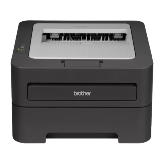
Summary of Contents for Brother HL-2230
- Page 1 Brother Laser Printer SERVICE MANUAL MODEL: HL- 2130/2135W/2220/2230/2240/ 2240D/2250DN/2270DW/2275DW Read this manual thoroughly before maintenance work. Keep this manual in a convenient place for quick and easy reference at all times. September 2010 SM-PRN079 84UC0* Confidential...
- Page 2 The contents of this manual and the specifications of this product are subject to change without notice. Brother reserves the right to make changes without notice in the specifications and materials contained herein and shall not be responsible for any damages (including consequential) caused by reliance on the materials presented, including but not limited to typographical and other errors relating to the publication.
-
Page 3: Table Of Contents
TABLE OF CONTENTS REGULATION ......................vi SAFETY INFORMATION ....................x CHAPTER 1 SPECIFICATIONS ................. 1-1 1. SPECIFICATIONS LIST ......................1-1 General ..........................1-1 Network Connectivity ......................1-4 Service Information ......................1-5 Supplies ..........................1-6 Paper ..........................1-7 1.5.1 Paper handling ....................... 1-7 1.5.2 Media specifications .................... - Page 4 4.1.6 Dirt on paper ......................2-25 4.1.7 Paper feeding at an angle ..................2-25 4.1.8 Wrinkles or creases ....................2-26 4.1.9 Curl in the paper ....................2-27 4.1.10 Prints only single side of the paper when duplex-printing ........2-28 4.1.11 Cannot make print through duplex-printing ............2-28 4.1.12 Paper size error ....................
- Page 5 Laser Unit Problems ......................2-44 4.7.1 Laser Unit failure ....................2-44 PCB Problems ........................2-45 4.8.1 Main PCB failure ....................2-45 4.8.2 Memory full ......................2-45 4.8.3 Print overrun ......................2-45 4.8.4 High voltage power supply PCB ASSY failure ............. 2-45 4.8.5 Low voltage power supply PCB ASSY failure ............
- Page 6 9.16 Laser Unit ......................... 3-45 9.17 Wireless LAN PCB ASSY (Wireless network model only) ..........3-47 9.18 Pick-up Roller Holder ASSY ..................... 3-48 9.19 Rubber Foot ........................3-49 9.20 Main PCB ASSY ....................... 3-50 9.21 T1 Clutch ASSY, REG Clutch ASSY ................3-51 9.22 Main Frame L ASSY ......................
- Page 7 CHAPTER 6 CIRCUIT DIAGRAMS, WIRING DIAGRAM ........6-1 CHAPTER 7 PERIODICAL MAINTENANCE ............7-1 1. PERIODICAL REPLACEMENT PARTS ..................7-1 APPENDIX 1 SERIAL NUMBERING SYSTEM .......... App. 1-1 APPENDIX 2 DELETION OF USER SETTING INFORMATION ....App. 2-1 APPENDIX 3 INSTALLING THE MAINTENANCE PRINTER DRIVER ..App. 3-1 APPENDIX 4 HOW TO MAKE PROTECTIVE MATERIAL OF DRUM UNIT ..
-
Page 8: Regulation
REGULATION <For Europe and Other countries> Radio interference (220 to 240 volt model only) This printer follows EN55022 (CISPR Publication 22)/Class B. IEC 60825-1: 2007 specification (220 to 240 volt model only) This printer is a Class 1 laser product as defined in IEC 60825-1: 2007 specifications. The label shown below is attached in countries where it is needed. - Page 9 Internal laser radiation Maximum radiation power: 25 mW Wave length: 770 - 800 nm Laser class: Class 3B EU Directive 2002/96/EC and EN50419 (European Union only) This equipment is marked with the recycling symbol below. It means that at the end of the life of the equipment you must dispose of it separately at an appropriate collection point and not place it in the normal domestic unsorted waste stream.
- Page 10 Important A shielded interface cable should be used to ensure compliance with the limits for a Class B digital device. Changes or modifications not expressly approved by Brother Industries, Ltd. could void the user’s authority to operate the equipment. viii...
- Page 11 FDA regulations and must be attached to laser products marketed in the United States. MANUFACTURED: Brother Technology (Shenzhen) Ltd. NO6 Gold Garden Ind., Nanling Nanwan, Longgang, Shenzhen, China This product complies with FDA performance standards for laser products except for deviations pursuant to Laser Notice No.50, dated Jun 24, 2007.
-
Page 12: Safety Information
SAFETY INFORMATION Caution for Laser Product (WARNHINWEIS fur Laser drucker) CAUTION: When the printer during servicing is operated with the cover open, the regulations of VBG 93 and the performance instructions for VBG 93 are valid. CAUTION: In case of any trouble with the laser unit, replace the laser unit itself. To prevent direct exposure to the laser beam, do not try to open the enclosure of the laser unit. - Page 13 Definitions of Warnings, Cautions, Notes and Memos The following conventions are used in this manual: Mark Contents Warnings tell you what to do to prevent possible personal injury. Electrical Hazard icons alert you to a possible electrical shock. Hot Surface icons warn you not to touch printer parts that are hot. Cautions specify procedures you must follow or avoid to prevent possible damage to the printer or other objects.
- Page 14 Safety Precautions Listed below are the various kinds of “WARNING” messages included in this manual. WARNING There are high voltage electrodes inside the printer. Before you clean the inside of the printer or replace parts, make sure that you have turned off the power switch and unplugged the printer from the AC power outlet.
- Page 15 WARNING DO NOT use flammable substances such as alcohol, benzine, thinner or any type of spray to clean the inside or outside of the printer. Doing this may cause a fire or electrical shock. If the printer becomes hot, blows smoke, or generates obscure odor, immediately turn off the power switch and unplug the printer from the AC power outlet.
-
Page 16: Chapter 1 Specifications
CHAPTER 1 SPECIFICATIONS SPECIFICATIONS LIST General Model HL-2130 HL-2135W HL-2220 HL-2230 Print method Electrophotographic / Laser Resolution 600 x 600 dpi, HQ1200 (2400 x 600 dpi) quality Print speed Up to 20/21 ppm (A4/Letter size) Up to 24/24 ppm (A4/Letter size) * When loading A4 or Letter-size paper from the paper tray. - Page 17 HL-2270DW/ Model HL-2240 HL-2240D HL-2250DN 2275DW Print method Electrophotographic / Laser Resolution 600 x 600 dpi, HQ1200 (2400 x 600 dpi) quality Print speed Up to 24/24 ppm Up to 26/27 ppm (A4/Letter size) (A4/Letter size) * When loading A4 or Letter-size paper from the paper tray. Warm-up time From Sleep mode Less than 7 seconds at 23°C (73.4 F) From Power...
- Page 18 <Computer requirements> Hard Computer Platform & Recom- Supported PC Processor Minimum Minimum Disk Operating System mended Speed Space Interface Version to install ® ® ® ® Windows Windows Intel Pentium II or 64 MB 256 MB 50 MB USB, 2000 equivalent 10BASE-T / Operating...
-
Page 19: Network Connectivity
Network Connectivity Model HL-2130 HL-2135W HL-2220 HL-2230 Wired network Network node type Network type Wireless network Network node NC-7800w type Network type IEEE 802.11b/g (Infrastructure Mode / Adhoc Mode) Network security N/A WEP 64/128 bit, WPA-PSK (TKIP/AES), WPA2-PSK (AES), APOP,... -
Page 20: Service Information
Service Information Model HL-2130 HL-2135W HL-2220 HL-2230 Printer life 50,000 pages (A4 / Letter) or 5 years under normal use at normal temperature and humidity. MTBF 4,000 hours MTTR 0.5 hours Maximum monthly volume Up to 8,000 pages Up to 10,000... -
Page 21: Supplies
Supplies Model HL-2130 HL-2135W HL-2220 HL-2230 Toner cartridge Starter Toner Approx. 700 pages Standard Toner Except for Approx. Approx. 1,200 pages Asia Approx. 1,000 pages 1,000 pages For Asia: 700 pages High Capacity Approx. 2,600 pages Toner Approx. cartridge yield is declared in accordance with ISO/IEC 19752... -
Page 22: Paper
Paper 1.5.1 Paper handling Model HL-2130 HL-2135W HL-2220 HL-2230 Paper Input Manual feed slot 1 sheet Paper tray 250 sheets Paper Output Face-down 100 Sheets (80g/m Face-up 1 sheet (straight paper path) HL-2270DW/ Model HL-2240 HL-2240D HL-2250DN 2275DW Paper Input... -
Page 23: Printable Area
Printable Area The area of the paper that cannot be printed on is shown in the table below: Portrait Letter Legal B5 (ISO) Executive B6 (ISO) 4.23 mm 4.23 mm 4.23 mm 4.23 mm 4.23 mm 4.23 mm 4.23 mm 4.23 mm (0.16 in.) (0.16 in.) -
Page 24: Chapter 2 Troubleshooting
CHAPTER 2 TROUBLESHOOTING INTRODUCTION Troubleshooting is the countermeasure procedures that the service personnel should follow if an error or malfunction occurs with the printer. It is impossible to anticipate all of the possible troubles which may occur in future and determine the troubleshooting procedures, so this chapter covers some sample troubles. -
Page 25: Initial Check
Initial Check Check the following items before attempting to repair the printer. ■ Operating Environment (1) Put your printer on a flat, stable surface such as a desk that is free of vibration and shocks. (2) Use the printer in a well-ventilated room; use the printer within the following ranges of temperature and humidity: temperature between 10°C and 32.5°C (50°F to 90.5°F), and the relative humidity is maintained between 20% and 80%. - Page 26 ■ Others (1) Condensation When the printer is moved from a cold place into a warm room, condensation may occur inside the printer, causing various problems as listed below. • Condensation on the optical surfaces such as the lenses, the reflection mirror and the protection glass may cause the print image to be light.
-
Page 27: Overview
OVERVIEW Cross-section Drawing <Back side> <Front side> Eject roller 2 Eject Pinch Roller Exposure drum Develop roller Supply roller Laser unit Registration rear actuator Back cover Manual paper tray cover Eject roller 1 Registration front actuator Regist roller Paper eject actuator Paper edge actuator... -
Page 28: Paper Feeding
Paper Feeding Rear paper eject path Manual feed slot path Paper tray path Duplex path Fig. 2-2 Confidential... -
Page 29: Operation Of Each Part
Operation of each part Part name Operation Pick-up roller Feed the paper from the paper tray. Separation roller and Separate into single sheet from the paper tray. Separation pad Paper edge actuator Detect the rear edge of paper, and identify the paper size. (HL-2250DN/2270DW/2275DW only) Registration front actuator... -
Page 30: Block Diagram
Block Diagram Wireless LAN PCB ASSY Registration front/rear sensor PCB Registration front sensor Panel PCB ASSY Paper Edge Sensor PCB Registration rear sensor (HL-2250DN/2270DW/ 2275DW only) Error LED Paper Edge Sensor Drum LED Low voltage power supply PCB Toner LED Heater Switch New toner sensor Ready LED... -
Page 31: Components
Components Top cover ASSY Top cover ASSY <HL-2130/2135W> <Except for HL-2130/2135W> Support flap 2 Top cover ASSY Support flap 2 Top cover base SW key Top cover ASSY SW key SW key holder Outer chute Back cover ASSY Pinch rollers ASSY Fuser cover Laser unit Fuser unit... -
Page 32: Led Error Indication And Failures
LED ERROR INDICATION AND FAILURES LED indication at Operator Calls Distinguish the contents of error by LED indication in the control panel. See the reference page and take the corrective action described for each indication to correct it. when the red Error LED is ON or blinking to indicate it, the printer automatically recovers from most errors. - Page 33 Type of error Refer to: DRUM END SOON 4.5.7 Drum On for 2 seconds Off for 3 seconds REPLACE DRUM 4.5.9 FRONT COVER OPEN 4.9.4 FUSER COVER OPEN 4.9.5 JAM TRAY1/JAM INSIDE 4.1.5 JAM REAR 4.1.5 JAM DUPLEX 4.1.5 MEMORY FULL 4.8.2 PRINT OVERRUN 4.8.3...
- Page 34 Type of error Refer to: TONER ENDED 4.5.5 DRUM ERROR 4.5.8 Drum LED and Error LED : On for 0.5 seconds Off for 0.5 seconds DRUM STOP 4.5.9 2-11 Confidential...
-
Page 35: Led Indication At Service Calls
LED indication at Service Calls If service calls occur, all four LEDs blink on and off to notice it. And then when press the [Go] button, distinguish a fault from the specific combination of ON/OFF and status color of the LEDs. When entering this state, instruct the end user to turn off the power switch once, and wait a few seconds. - Page 36 Pressing one time Pressing two times Refer Type of error of the [Go] button of the [Go] button Fuser unit failure 4.6.1 On for 0.5 seconds Fuser Unit Failure LEDs Off for 0.5 seconds 2-13 Confidential...
- Page 37 Pressing one time Pressing two times Refer Type of error of the [Go] button of the [Go] button Laser unit failure 4.7.1 Polygon motor failure Laser Unit Failure 4.7.1 Main PCB failure On for 0.5 seconds LEDs Off for 0.5 seconds 4.8.1 Main PCB Failure 2-14...
- Page 38 Pressing one time Pressing two times Refer Type of error of the [Go] button of the [Go] button Main PCB failure 4.8.1 On for 0.5 seconds Main PCB Failure LEDs Off for 0.5 seconds 2-15 Confidential...
- Page 39 Pressing one time Pressing two times Refer Type of error of the [Go] button of the [Go] button High voltage power supply PCB ASSY failure 4.8.4 High Voltage Failure Main motor failure 4.9.3 Fuser fan failure or Harness connection failure of T1 clutch ASSY On for 0.5 seconds...
-
Page 40: Error Messages In The Status Monitor
Error messages in the Status Monitor The Status Monitor will report problems with the printer. Take the proper action by seeing to the reference page. Error message Refer to: CANNOT DETECT TONER 4.5.2 DRUM END SOON 4.5.7 DRUM ERROR 4.5.8 DRUM STOP 4.5.9 DUPLEX DISABLED*... -
Page 41: Error Indication At Service Calls
Error indication at Service Calls If LED indication does not operate when service calls occur, distinguish the type of error by operating the Printer Settings printing or Maintenance printing. If you can not print, you can use a Status Monitor to distinguish the type of error. Error indication Error indication Status... - Page 42 ■ How to display Status Code with Status Monitor (1) Connect the computer to the machine with the USB cable. (2) Start up the Status Monitor. Dialog below appears. (3) Double-click on the Status Monitor dialog. Log data below appears. Check Status fields of log data.
-
Page 43: Image Defect Examples
Image Defect Examples 4.2.1 4.2.2 4.2.3 4.2.4 4.2.5 Light Faulty registration Dark Poor fixing Completely blank 4.2.8 4.2.9 4.2.6 4.2.7 Vertical streaks The back of paper gets dirty Image All black distortion 4.2.10 4.2.11 4.2.12 4.2.13 4.2.14 Black vertical Black horizontal White vertical White horizontal Faint print... -
Page 44: Error Symptom/Error Cause And Remedy
ERROR SYMPTOM/ERROR CAUSE AND REMEDY Paper Feeding Problems Problems related to paper feeding are end user recoverable if following the User Check items. If the same problem occurs again, follow each procedure in the order of the number described in the Step column in the tables below. 4.1.1 Pickup function of Paper tray does not work. -
Page 45: No Paper Fed Manual Feed Slot
4.1.3 No paper fed manual feed slot Not detect paper at feeding from manual feed slot User Check • Load the paper into the manual feed slot. Step Cause Remedy Harness connection failure of Check the harness connection of the registration front/rear sensor PCB registration front/rear sensor PCB ASSY, ASSY... -
Page 46: Paper Jam
4.1.5 Paper jam • Paper tray and front cover section Paper jam at paper tray and front cover section User Check • Check if the paper is jammed in the paper tray and front cover section. If jammed, remove it. •... - Page 47 • Jam inside/Jam rear Paper jam inside and rear of the printer User Check • Check if the paper is jammed inside and rear side of the printer. If jammed, remove it. • Check if the back cover is closed certainly. •...
-
Page 48: Dirt On Paper
• Duplex unit Paper jam in the duplex tray User Check • Insert the duplex tray correctly. • Check if the paper is jammed in the duplex tray. Step Cause Remedy Foreign object around duplex tray Remove the foreign object around the duplex tray. -
Page 49: Wrinkles Or Creases
4.1.8 Wrinkles or creases User Check • Check if the paper is no damp. • Check if the paper is loaded into the paper tray correctly. • Check if the thickness of the paper is 60 to 105 g/m • Turn over the stack of paper in the paper tray, or try rotating the paper 180° in the paper tray. -
Page 50: Curl In The Paper
4.1.9 Curl in the paper User Check • Choose Reduce Paper Curl mode in the driver. • Turn the anti-curl levers to the direction of the black arrow. (Refer to Fig. 2-7.) • Lift up the support flap2, and then print. Step Cause Remedy... -
Page 51: Prints Only Single Side Of The Paper When Duplex-Printing
4.1.10 Prints only single side of the paper when duplex-printing User Check • Set the driver setting to the duplex-printing. • Use the paper of the A4/LETTER. 4.1.11 Cannot make print through duplex-printing User Check • Check if the back cover is closed certainly. •... -
Page 52: Troubleshooting Image Defect
Troubleshooting Image Defect Image defect related problems are end user recoverable if following the User Check items. If the same problem occurs, follow each procedure in the order of the number described in the Step column in the tables below. 4.2.1 Light User Check •... - Page 53 ■ Electrodes location of the toner cartridge and drum unit Side surface of Drum unit Fig. 2-8 ■ Electrodes location of the printer Fig. 2-9 <How to clean the electrodes> Turn off the power switch. Unplug the printer from the AC power outlet, and leave the printer for a few minutes.
-
Page 54: Faulty Registration
4.2.2 Faulty registration User Check • Check that the appropriate media type is selected in the driver. Step Cause Remedy Adjusted value of the laser unit Refer to "2.1 Inputting the adjusted value of mistake the laser unit" (Chapter 4), and enter the adjusted value of the laser unit again. -
Page 55: Poor Fixing
4.2.4 Poor fixing User Check • Check the printer's environment. High temperature and high humidity or low temperature and low humidity conditions can cause this problem. • Clean the corona wire of drum unit. • Replace the drum unit with a new one. •... -
Page 56: Image Distortion
4.2.6 Image distortion Step Cause Remedy Laser unit not assembled correctly Assemble the laser unit correctly and secure the screw. Laser unit failure Replace the laser unit. Main PCB failure Replace the main PCB ASSY. 4.2.7 All black User Check •... -
Page 57: Vertical Streaks
4.2.9 Vertical streaks User Check • This problem may occur with noise which is caused by dirt on the corona wire in the drum unit. In this case, clean the corona wire. • If the same problem occurs after printing a few pages, the adhesive of the label or the like, paper powder or dirt may be attached on the surface of the exposure drum. -
Page 58: Black Horizontal Stripes
4.2.11 Black horizontal stripes User Check • Clean the inside of the printer and the corona wire in the drum unit. • When the horizontal stripes at 94.2 mm are intervals, replace the drum unit with a new one. • The paper tray ground terminal provided in the printer body may be dirty. -
Page 59: White Vertical Streaks
4.2.12 White vertical streaks User Check • Check if there is no dust in the gap between the toner cartridge and drum unit. • Replace the toner cartridge with a new one. • Check the printer's environment. High temperature and high humidity or low temperature and low humidity conditions can cause this problem. -
Page 60: White Spots
4.2.15 White spots User Check • When the white spots at 32.5 mm are intervals, replace the toner cartridge with a new one. • If the same problem occurs after printing a few pages, the adhesive of the label or the like, paper powder or dirt may be attached on the surface of the exposure drum. -
Page 61: Black Band
4.2.17 Black band User Check • Clean the inside of the printer and the corona wire in the drum unit. If the same problem occurs after cleaning, replace the drum unit with a new one. • The paper tray ground terminal provided in the printer body may be dirty. -
Page 62: Ghost
4.2.20 Ghost User Check • Check the printer's environment. High temperature and high humidity or low temperature and low humidity conditions can cause this problem. • Choose Reduce Ghosting mode in the driver. • Replace the toner cartridge with a new one. Step Cause Remedy... -
Page 63: Software Setting Problems
(4) Select the “HL-XXXX” in the “USB Device Tree”. (5) Check the “Product ID” in the “HL-XXXX”. Product ID (Hexadecimal) • HL-2130/2135W : 003Fh • HL-2220 : 0046h • HL-2230 : 0044h • HL-2240 : 0045h • HL-2240D : 0040h • HL-2250DN : 0041h •... -
Page 64: Network Problems (Network Model Only)
Network Problems (Network model only) 4.4.1 Cannot make a print through network connection User Check • Check the descriptions in the network user’s guide. • Reset the printer back to its default printer settings. (Refer to “Settings Reset” in Chapter 5.) •... -
Page 65: Toner & Drum Problems
Toner & Drum Problems 4.5.1 If replace toner, cannot delete "Replace Toner". User Check • Install a new toner cartridge certainly. Step Cause Remedy New toner actuator catching on Correct catching of the new toner some position actuator. Harness connection failure of Panel Reconnect the harness of the Panel PCB. -
Page 66: The Number Of Rotations Of The Developer Roller Reaches The Upper Limit
4.5.5 The number of rotations of the developer roller reaches the upper limit User Check • Replace the toner cartridge with a new one. Step Cause Remedy New toner actuator loose Re-assemble the new toner actuator (If replace the new toner, “TONER ENDED”... -
Page 67: Fuser Unit Problems
Fuser Unit Problems 4.6.1 Fuser Unit failure Step Cause Remedy Harness connection failure between Check the harness connection between fuser unit connector and paper eject fuser unit connector and paper eject sensor PCB ASSY sensor PCB ASSY, and reconnect it. Harness connection failure between Check the harness connection between fuser unit connector and low voltage... -
Page 68: Pcb Problems
PCB Problems 4.8.1 Main PCB failure User Check • Turn the power off and on. Step Cause Remedy Firmware update failure Rewrite the latest firmware. Main PCB failure Replace the main PCB ASSY. 4.8.2 Memory full Memory full User Check •... -
Page 69: Low Voltage Power Supply Pcb Assy Failure
4.8.5 Low voltage power supply PCB ASSY failure User Check • Turn the power off and on. Step Cause Remedy Harness connection failure of low Check the harness connection of the low voltage power supply PCB ASSY voltage power supply PCB ASSY, and reconnect it. -
Page 70: Main Motor Failure
4.9.3 Main motor failure Step Cause Remedy Flat cable connection failure of the Check the flat cable connection of the main motor main motor, and reconnect it. Main motor failure Replace the main motor. Low voltage power supply PCB Replace the low voltage power supply ASSY failure PCB ASSY. -
Page 71: Chapter 3 Disassembly And Assembly
CHAPTER 3 DISASSEMBLY AND ASSEMBLY SAFETY PRECAUTIONS To avoid creating secondary problems by mishandling, follow the warnings and precautions below during maintenance work. WARNING • Always turn off the power switch and unplug the power cord from the power outlet before accessing any parts inside the printer. -
Page 72: Packing
PACKING Set guide DEMO Insertion Printed bag ASSY Option carton AC cord USB IF cable Printer Carton Fig. 3-1 Confidential... -
Page 73: Screw Catalogue
SCREW CATALOGUE Taptite bind B Taptite bind B M3x10 Taptite bind B M4x12 Screw bind B Screw bind M3x4 Taptite pan B Taptite pan B M3x8 Taptite pan B M4x14 Taptite cup B Taptite cup B M3x8 Taptite cup S Taptite cup S M3x6 SR Taptite cup S... -
Page 74: Screw Torque List
SCREW TORQUE LIST Tightening torque Location of screw Screw type Q’ty N · m (kgf · cm) Tray cover Taptite bind B M4x12 0.8±0.1 (8±1) Inner chute ASSY Taptite bind B M4x12 0.8±0.1 (8±1) Top cover base (Top cover ASSY Taptite bind B M4x12 0.8±0.1 (8±1) <except for HL-2130/2135W>) -
Page 75: Lubrication
LUBRICATION The kind of the lubricating oil Lubrication point Quantity of lubrication (Maker name) BG-10KS 2mm dia. ball Dev gear joint/52 (Kanto Kasei) 4 places Dev gear joint/52 Fig. 3-3 Confidential... -
Page 76: Overview Of Gears
OVERVIEW OF GEARS ■ Paper feeder part <Layout view> Fig. 3-4 <Development view> Fig. 3-5 <Name of gears> LY2584 Feeder gear 17 LY2046 Feeder gear idle 65 LY2047 Feeder gear LY2045 Feeder gear 21/30/17 LY2581 Feeder gear holder LY2044 Feeder gear 41 LY2582 Feeder gear spring LY2043 Feeder gear 31 pendulum LY2583 Feeder holder spring... - Page 77 ■ Development part <Layout view> Fig. 3-6 <Development view> Fig. 3-7 <Name of gears> LY2064 Develop joint link 12 LY2063 DEV gear 33 10 LY2458 Develop joint lift cam 13 LY2062 DEV gear 21/45R 11 LU2041 Develop joint lift disk * These parts are subject to change without prior notice Confidential...
- Page 78 ■ Paper eject & Duplex part <Layout view> Fig. 3-8 <Development view> Fig. 3-9 <Name of gears> 14 LY2011 Ejector gear 10/15 20 LY2015 DX gear 16/20 15 LY2012 Ejector gear 22 21 LY2016 DX gear 19 16 LY2013 Ejector gear 40 22 LY2454 DX gear 21M1/21M0.8 17 LY2010 Fuser gear 28/34 23 LY2038 DX gear 18 pendulum...
-
Page 79: Harness Routing
HARNESS ROUTING Paper edge sensor PCB ASSY (HL-2250DN/2270DW/2275DW only) Panel PCB ASSY Guide Printer top side Paper edge sensor harness ASSY Paper edge sensor PCB ASSY Confidential... - Page 80 Registration front/rear sensor PCB ASSY Guide Printer top side Low voltage power supply PCB ASSY Registration F/R sensor harness ASSY Registration front/rear sensor PCB ASSY Panel PCB ASSY Guide Panel PCB ASSY Main PCB ASSY 3-10 Confidential...
- Page 81 T1 Clutch ASSY, REG Clutch ASSY Main PCB ASSY Guide Guide REG clutch ASSY Guide T1 clutch ASSY 3-11 Confidential...
- Page 82 Paper eject sensor PCB ASSY Paper eject sensor PCB ASSY Back cover sensor Guide Back cover Hooks sensor harness Main PCB ASSY Main frame L ASSY Main shield Main PCB sheet Main-eject sensor flat cable harness 3-12 Confidential...
- Page 83 Main Motor Main PCB ASSY Main motor Laser Unit Laser unit Main PCB ASSY Hole of guide Guide Main-scanner flat cable Harness 3-13 Confidential...
- Page 84 Wireless LAN PCB ASSY (Wireless network model only) Wireless PCB harness ASSY Main PCB ASSY Guide Guide Wireless LAN PCB ASSY Fuser fan Hole of guide Hole of guide Tape High voltage power supply PCB ASSY Guide Fuser fan 3-14 Confidential...
- Page 85 Low voltage power supply PCB ASSY LVPS harness ASSY Low voltage power supply PCB ASSY <Right side> Main PCB ASSY Guide <Left side> 3-15 Confidential...
- Page 86 High voltage power supply PCB ASSY Guide Guide Main-HVPS flat cable harness Guide Guide Main PCB ASSY High voltage power supply PCB ASSY Fuser Unit Heater harness Guide Fuser unit Guide Main frame L ASSY Side thermistor harness ASSY Center thermistor harness ASSY Main frame R ASSY 3-16 Confidential...
-
Page 87: Disassembly Flow
DISASSEMBLY FLOW 9.18 Pick-up Roller Duplex Tray 9.1 Paper Tray 9.6 Support Flap 1 9.9 Support Flap 2 9.19 Rubber Foot Holder ASSY 10/10 10/10 35/40 Disassembly / Re-Assembly second 9.20 Main PCB 9.20 Main PCB 9.7 Side Cover L ASSY Sheet 15/15... -
Page 88: Disassembly Procedure
DISASSEMBLY PROCEDURE ■ Preparation Prior to proceeding with the disassembly procedure, (1) Unplug • the AC cord, • the USB cable, if connected, • the LAN cable, if connected. (2) Remove • the Paper tray, • the Toner cartridge and Drum unit, •... -
Page 89: Paper Tray
Paper Tray (1) Remove the two Taptite bind B M4x12 screws, and release the two Bosses (Upper side), and remove the Tray cover from the Paper tray. Taptite bind B M4x12 Tray cover Bosses Back side view Back side view Bosses Paper tray Fig. - Page 90 (2) Release the Hooks of the Separation pad ASSY from the Paper tray. (3) Press both side Arms of the Separation pad ASSY to remove the Bosses, and remove the Separation pad ASSY from the Paper tray. (4) Remove the Separation pad spring from the Separation pad ASSY. Separation pad ASSY Boss Arms...
- Page 91 (5) Push the Hook of the Lift gear 46 while pushing up the Plate up plate, and remove the Lift gear 46. Plate up plate Hook Lift gear 46 Paper tray Fig. 3-14 (6) Remove the Gear Z23M10Z14M75 and the Gear Z19M10. Gear Z19M10 Paper tray Gear Z23M10Z14M75...
-
Page 92: Back Cover
Back Cover <With Duplex Tray model> (1) Open the Back cover. (2) Push the both side Ribs of the Back cover to the direction of the arrow 2, and release the Boss of the Outer chute ASSY. (3) Release the Boss of the Main body while pulling the Back cover to the direction of the arrow 3a, and remove the Back cover. - Page 93 <Without Duplex Tray model> (1) Open the Back cover. (2) Push the both side Ribs of the Back cover to the direction of the arrow 2, and release the Boss of the Outer chute ASSY. (3) Release the Boss of the Main body while pulling the Back cover to the direction of the arrow 3a, and remove the Back cover.
-
Page 94: Outer Chute Assy
Outer Chute ASSY (1) Pull the Outer chute ASSY to the direction of the 1a, and release the Boss of the Outer chute ASSY from the Main frame L ASSY, and remove the Outer chute ASSY. Main frame L ASSY Boss Outer chute ASSY Boss... -
Page 95: Fuser Cover
Fuser Cover (1) Hold the Knobs on the Fuser cover, and pull down this to your side. (2) Release the boss of the main body while pulling the Fuser cover to the direction of the arrow 2a, and remove Fuser cover. Knob Fuser cover Knob... -
Page 96: Inner Chute Assy, Eject Pinch Roller R Assy And Eject Pinch Roller L Assy
Inner Chute ASSY, Eject Pinch Roller R ASSY and Eject Pinch Roller L ASSY (1) Pull down both side Green envelope levers of the Fuser unit. (2) Remove the two Taptite bind B M4x12 screws to remove the Inner chute ASSY. Positioning holes Fuser unit Green envelope lever R... - Page 97 (3) Remove the two Eject pinch roller L ASSY and the two Eject pinch roller R ASSY from the Inner chute ASSY. (4) Remove the four Exit pinch roller springs from the Eject pinch roller L ASSY and the Eject pinch roller R ASSY. Eject pinch roller R ASSY Eject pinch roller L ASSY Exit pinch roller springs...
-
Page 98: Front Cover Assy, Support Flap 1
Front Cover ASSY, Support Flap 1 (1) Open the Front cover ASSY. (2) Release the Hooks of the Develop joint link to remove the Develop joint link from the Front cover ASSY. (3) Pull up the Rib of the Front chute ASSY to the direction of the arrow 3a, and silid the Front cover ASSY to the direction of the arrow 3b and 3c, and remove it. -
Page 99: Side Cover L
Side Cover L (1) Release the Hooks in the order of 1a, 1b and 1c, and remove the Side cover L. Hook Hook Side cover L Hooks Hook Fig. 3-24 3-29 Confidential... -
Page 100: Side Cover R
Side Cover R (1) Release the Hooks in the order of 1a, 1b and 1c, and remove the Side cover R. Hooks Hook Hooks Side cover R Hook Hook Fig. 3-25 3-30 Confidential... -
Page 101: Top Cover Assy
Top Cover ASSY (1) Release the Hooks of the Top cover ASSY from A to F. (2) Pull the Top cover ASSY to the direction of the arrow 2a, and remove it from the Main body. Hook Top cover ASSY Hook F Hook Hook B... - Page 102 (3) Remove the Support flap 2 from the Top cover ASSY. Support flap 2 Top cover ASSY Fig. 3-27 (4) Turn the Top cover ASSY upside down. (5) Remove the two Paper stack levers from the Top cover ASSY. Paper stack levers Top cover ASSY Fig.
- Page 103 (Top cover ASSY <except for HL-2130/2135W>) (6) Remove the two Taptite bind B M4x12 screws. (7) Release the four Hooks and two Ribs of the Top cover ASSY, and remove the Top cover base from the Top cover ASSY. (8) Remove the SW key from the Top cover ASSY. Taptite bind B M4x12 Top cover base Claw...
- Page 104 (Top cover ASSY <HL-2130/2135W>) (6) Remove the Taptite pan B M3x8 screw, and remove the SW key holder and the SW key from the Top cover ASSY. Taptite pan B M3x8 SW key holder SW key Top cover ASSY Fig. 3-30 3-34 Confidential...
-
Page 105: Fuser Unit
9.10 Fuser Unit (1) Release the Harness of the Fuser unit from the Guides of the Main frame R ASSY. (2) Disconnect the Connector of the Low voltage power supply PCB ASSY while pushing the Hook of the Connector of the Fuser unit. Guides Connector (low voltage power... - Page 106 (4) Disconnect the Connectors of the center thermistor harness ASSY and the side thermistor harness ASSY from the Paper eject sensor PCB ASSY. (5) Release the harnesses of the center thermistor harness ASSY and the side thermistor harness ASSY from the Guides of the Main frame L ASSY. Guide Side thermistor harness ASSY Guides...
- Page 107 (6) Remove the two Taptite pan B M4x14 screws to remove the Fuser unit. Fuser unit Taptite pan B M4X14 Fig. 3-34 3-37 Confidential...
-
Page 108: Low Voltage Power Supply Pcb Assy
9.11 Low voltage power supply PCB ASSY (1) Remove the FG spring front chute from the LV shield plate cover and the Front chute ASSY. (2) Release the Hook part of the FG wire under R from the LV shield plate cover. (3) Remove the three Taptite bind B M4x12 screws, the Screw pan (S/P washer) M3.5x6 screw and the Screw pan (S/P washer) M3x12DB screw to remove the LV shield plate cover. - Page 109 (4) Remove the Screw pan (S/P washer) M3.5x6 screw to remove the FG harness from the Low voltage power supply PCB ASSY. (5) Remove the Taptite flat B M3x10 screw to remove the Inlet of the Low voltage power supply PCB ASSY. (6) Release the Hooks to remove the Power switch of the Low voltage power supply PCB ASSY.
- Page 110 (9) Remove the Low voltage power supply PCB ASSY, and disconnect the three connectors from the rear side. (10) Remove the LV insulation sheet. Connectors Low voltage power supply PCB ASSY LV insulation sheet Fig. 3-38 3-40 Confidential...
-
Page 111: Fuser Fan
9.12 Fuser fan (1) Disconnect the Connector of the Fuser fan from the High voltage power supply PCB ASSY. (2) Remove the Harness of the Fuser fan from the Guides of the Main frame R ASSY. (3) Release the Hooks to remove the Fuser fan. Connector Guides Tape... -
Page 112: High Voltage Power Supply Pcb Assy
9.13 High voltage power supply PCB ASSY (1) Remove the Flat cable from the Guides of the Main frame R ASSY, and disconnect the connector from the High voltage power supply PCB ASSY. (2) Remove the Taptite bind B M4x12 screw. (3) Release the Hooks to remove the High voltage power supply PCB ASSY. -
Page 113: Panel Pcb Assy
9.14 Panel PCB ASSY (1) Rotate the Main body 180° to the side of Main frame L ASSY. (2) Disconnect the Flat cable of the Panel PCB ASSY from the Main PCB ASSY, and remove the Flat cable of the Panel PCB ASSY from the Guide of the Main frame L ASSY. -
Page 114: Filter
9.15 Filter (1) Release the Hooks to remove the Air duct. (2) Pull the Rib of the Air duct to the direction of the arrow 2a, and remove the Filter. Hooks Air duct Air duct Filter Pins Pins Pins Air duct Fig. -
Page 115: Laser Unit
9.16 Laser Unit (1) Disconnect the flat cable of the high voltage power supply PCB ASSY from the main PCB ASSY, and remove the flat cable of the high voltage power supply PCB ASSY from the guide of the main frame L ASSY. (2) Disconnect the flat cable of the laser unit from the laser unit. - Page 116 Assembling Note: • There are three types of Laser unit that can be ordered as a spare part. (SG type Laser unit is compatible with SJ type Laser unit. SH type Laser unit is compatible with SK type Laser unit.) <How to identify the type of Laser unit and the position of label>...
-
Page 117: Wireless Lan Pcb Assy (Wireless Network Model Only)
9.17 Wireless LAN PCB ASSY (Wireless network model only) (1) Remove the Harness of the Wireless LAN PCB ASSY from the Guides of the Main frame L ASSY. (2) Disconnect the Connector of the Wireless LAN PCB ASSY from the Main PCB ASSY. (3) Release the Hooks to remove the Wireless LAN PCB ASSY. -
Page 118: Pick-Up Roller Holder Assy
9.18 Pick-up Roller Holder ASSY (1) Turn the Printer upside down. (2) Push the Link arm to the direction of the arrow 2, and turn the Pick-up roller holder ASSY to release the boss. (3) Slide the Pick-up roller holder ASSY to the direction of the arrow 3 to release it from the shaft, and remove the Pick-up roller holder ASSY from the Main body. -
Page 119: Rubber Foot
9.19 Rubber Foot (1) Remove the two Rubber foots from the Main body. Rubber foot Rubber foot Main body Fig. 3-48 3-49 Confidential... -
Page 120: Main Pcb Assy
9.20 Main PCB ASSY (1) Turn the Printer upside down. (2) Disconnect the two Flat cables and the four Connectors from the Main PCB ASSY. (3) Remove the four Taptite cup S M3x6 SR screws. (4) Release the Hook to remove the Main PCB ASSY and the Main PCB sheet. Hook Connectors Main PCB sheet... -
Page 121: T1 Clutch Assy, Reg Clutch Assy
9.21 T1 Clutch ASSY, REG Clutch ASSY (1) Remove the Harness of the T1 clutch ASSY and the REG clutch ASSY from the Guides of the Main frame L ASSY. (2) Release the Hook to remove the T1 clutch ASSY. (3) Remove the retaining ring. - Page 122 (5) Remove the FG spring regist from the Motor drive sub ASSY and the Conductive bearing 5. (6) Remove the Conductive bearing 5 from the Pin of the Main frame L ASSY, and turn it to the direction of the arrow 5a until the releasing position, and pull out the Conductive bearing 5 from the Registration roller shaft 2.
-
Page 123: Main Frame L Assy
9.22 Main Frame L ASSY (1) Remove the two Taptite bind B M4x12 screws to remove the Front chute ASSY. (2) Remove the Paper edge sensor harness ASSY from the Guides of the Main frame L ASSY. Front chute ASSY Taptite bind B M4x12 Guides Paper edge sensor... - Page 124 (3) Place the printer so that the Main frame L ASSY is at the top. (4) Remove the LVPS harness ASSY from the Guide of the Main frame L ASSY. (5) Remove the Taptite bind B M4x12 screw 5a (for Under bar). (6) Remove the Taptite cup S M3X6 SR screw 6a (for Chute ground plate), the Taptite bind B M4x12 screw 6b (for PF frame ASSY) and the Taptite cup S M3x6 SR screw 6c (for FG plate laser L).
-
Page 125: Develop Drive Sub Assy, Develop Gear Joint/52
9.23 Develop Drive Sub ASSY, Develop Gear Joint/52 (1) Remove the Taptite cup S M3X6 SR screw and three Taptite bind B M4x12 screws to remove the Develop drive sub ASSY. Taptite bind B M4x12 Develop drive sub ASSY Taptite cup S M3X6 SR FG plate laser L Fig. - Page 126 (2) Place the Develop drive sub ASSY as shown in the figure below. (3) Be careful not to damage the Hooks of the Develop joint and release the Hooks to remove the Develop joint, and then remove the Develop joint spring and the Develop gear joint/52.
-
Page 127: Motor Drive Sub Assy, Main Motor
9.24 Motor Drive Sub ASSY, Main Motor (1) Remove the six Taptite bind B M4x12 screws to remove the Stopper and Motor drive sub ASSY. Taptite bind B M4x12 Taptite bind B M4x12 Stopper Motor drive sub ASSY Fig. 3-56 Assembling Note: •... - Page 128 (2) Place the Motor drive sub ASSY as shown in the figure below. (3) Remove the Drum gear 26L/131L. (4) Remove the three Screw bind M3x4 screws to remove the Main motor. Drum gear 26L/131L Screw bind M3x4 Motor drive sub ASSY Screw bind M3x4 Main motor Fig.
-
Page 129: Paper Eject Sensor Pcb Assy
9.25 Paper Eject Sensor PCB ASSY (1) Remove the Taptite cup S M3x6 SR screw and the two Taptite bind B M4x12 screws. (2) Release the Hooks to remove the Main PCB shield. Taptite bind B M4x12 Taptite cup S M3X6 SR Main PCB shield Hook Hook... - Page 130 (3) Release the Hook to remove the Paper eject sensor PCB ASSY from the Pin of the Main frame L ASSY. (4) Remove the Harness of the Paper eject sensor PCB ASSY from the Guides of the Main frame L ASSY. (5) Release the Hooks to remove the Back cover sensor.
-
Page 131: Fuser Gear 28/34
9.26 Fuser Gear 28/34 (1) Remove the Ejector gear 40. (2) Remove the Fuser gear 28/34. Ejector gear 40 Fuser gear 28/34 Fig. 3-60 3-61 Confidential... -
Page 132: Chapter 4 Adjustments And Updating Of Settings, Required After Parts Replacement
CHAPTER 4 ADJUSTMENTS AND UPDATING OF SETTINGS, REQUIRED AFTER PARTS REPLACEMENT IF YOU REPLACE THE MAIN PCB ASSY <What to do when replacing the main PCB ASSY> • Rewriting the Firmware (Main Program) • Setting the default paper size • Setting the serial number •... -
Page 133: Rewriting The Firmware (Main Program)
The following screen appears. Select the "Brother Maintenance USB Printer". (7) Drag the firmware (LZXXXX_$.blf) and drop it onto the Brother Maintenance USB Printer icon. The firmware files are sent to the printer and they are written into the flash ROM automatically. -
Page 134: Setting The Default Paper Size
(5) Double-click the "FILEDG32.EXE" on PC to start. The following screen appears. Select the "Brother Maintenance USB Printer". (6) Drag "DefaultPaperA4.pjl" (A4 size), "DefaultPaperLtr.pjl" (Letter size) or "DefaultPaperIsr.pjl" (A4 size, Israel font for Israel) and drop it onto the Brother Maintenance USB Printer icon. Note : •... -
Page 135: Setting The Serial Number
(2) Double-click the brusbsn.exe file which has been copied in the "hl2200" folder to start. (3) Click the Laser 10Model. (4) In Port on the brusbsn screen, select the port number assigned to the Brother Maintenance USB Printer. If the port number is unknown, follow steps below. - Page 136 The Brother Maintenance USB Printer Properties window appears as shown below. 4) Click the Ports tab. In this example, the port number assigned to the Brother Maintenance USB Printer is USB001. (5) Enter the serial number (the fifteen digits) of the printer into the box on the “Serial No”.
-
Page 137: Inputting The Adjusted Value Of The Laser Unit
Inputting the adjusted value of the laser unit Note: • When replace the laser unit, make sure to attach the laser serial label which is provided with the new laser unit to the laser plate. • When input the adjusted value, make sure to refer to the laser serial label which is provided with the new laser unit. - Page 138 (1) Double-click the brusbsn.exe file to start. (2) Click the Laser 10Model. (3) In Port on the brusbsn screen, select the port number assigned to the Brother Maintenance USB Printer. If the port number is unknown, follow steps below. 1) Click Start | Settings | Printers.
- Page 139 2) Right-click the Brother Maintenance USB Printer icon. 3) Click Properties. The Brother Maintenance USB Printer Properties window appears as shown below. 4) Click the Ports tab. In this example, the port number assigned to the Brother Maintenance USB Printer is USB001. Confidential...
- Page 140 (4) Enter the serial number (second digit) shown on the laser serial label attached on the figure below into the box on the “S xxxxxxVXXYY”. (5) Enter the serial number (the last five digits) into the box on the “Scanner Video Clk.”. (6) Click the [OK] button.
-
Page 141: If You Replace The Laser Unit
IF YOU REPLACE THE LASER UNIT Inputting the adjusted value of the laser unit Note: • When replace the laser unit, make sure to attach the laser serial label which is provided with the new laser unit to the laser plate. •... - Page 142 (1) Double-click the brusbsn.exe file to start. (2) Click the Laser 10Model. (3) In Port on the brusbsn screen, select the port number assigned to the Brother Maintenance USB Printer. If the port number is unknown, follow steps below. 1) Click Start | Settings | Printers.
- Page 143 2) Right-click the Brother Maintenance USB Printer icon. 3) Click Properties. The Brother Maintenance USB Printer Properties window appears as shown below. 4) Click the Ports tab. In this example, the port number assigned to the Brother Maintenance USB Printer is USB001. 4-12 Confidential...
- Page 144 (4) Enter the serial number (second digit) shown on the laser serial label attached on the figure below into the box on the “S xxxxxxVXXYY”. (5) Enter the serial number (the last five digits) into the box on the “Scanner Video Clk.”. (6) Click the [OK] button.
-
Page 145: If You Replace The Low Voltage Power Supply Pcb Assy
(4) Connect the printer to PC with USB cable. (5) Double-click the "FILEDG32.EXE" on PC to start. The following screen appears. Select the "Brother Maintenance USB Printer". (6) Drag the SQWAVE.PJL and drop it onto the Brother Maintenance USB Printer icon. 4-14 Confidential... -
Page 146: Chapter 5 Service Functions
CHAPTER 5 SERVICE FUNCTIONS The maintenance mode is exclusively designed for the purpose of checks, settings and adjustments using the buttons on the control panel or open/close of the front cover. You can perform operational checks of sensors, perform a print test, display the log information or error codes. -
Page 147: Maintenance Mode
MAINTENANCE MODE How to Enter the End User-accessible Maintenance Mode Basically, the maintenance-mode functions should be accessed by service personnel only. However, you can allow end users to access some of these under the guidance of service personnel (e.g., by telephone). <Procedure>... -
Page 148: List Of Maintenance Mode Functions
List of Maintenance Mode Functions <How to enter the end user-accessible maintenance mode> Press the [Go] button Front Press the [Go] button Refer when selecting the Function cover when sifting the mode function Close None Once 1) Test Sample Page Twice 2) Print Fonts (Network model only) - Page 149 Press the [Go] button Front Press the [Go] button Refer when selecting the Function cover when sifting the mode function Open Twice Once 18) Printing for Maintenance Twice 19) Maintenance and Frame 5-11 Pattern Print Three times 20) Network Configuration Print (Network Model 5-11 Only)
-
Page 150: Detailed Description Of Maintenance-Mode Functions
Detailed Description of Maintenance-mode Functions ■ End user-accessible maintenance mode Test Sample Page The printer prints a demo page. The printer returns to the ready state after printing. Print Fonts (Network model only) The printer prints a list of the internal fonts. The printer returns to the ready state after printing. - Page 151 Network Default Settings (Network Model only) Factory Reset Settings Reset Delete area of each reset is as follows. Network Factory Settings Data item default reset reset settings Printer switch - Counter information Error history MAC address User switches (Items to be initialized when resetting to the factory default settings) Function settings except user switches...
- Page 152 ■ Service personnel-accessible maintenance mode 10) Operational Check of Sensors This function allows you to check each of the sensors, electromagnetic clutch and motor. In the operational check of sensors, the Ready LED blinks once when the state of a sensor or a switch is changed (from ON to OFF, or from OFF to ON).
- Page 153 ■ Operational check of electromagnetic clutch When detect that the state of registration front sensor is changed, the regist electromagnetic clutch is 200msON. When detect that the state of new toner sensor is changed, the pickup electromagnetic clutch is 200msON. CAUTION : •...
- Page 154 16) Duplex Setting (ON/OFF) Switch the ON/OFF of the duplex setting. Whenever you switch this mode, the setting is changed over from the present one to the other. You can verify the setting change by LEDs when releasing the [Go] button. When the setting is completed, the printer return to the ready state.
- Page 155 PCB Information (0: HL-2130/2135W Toner Yield 1000, 1: HL-2240D, 2: HL-2250DN, 3: HL-2270DW/2275DW, 4: HL-2130 Toner Yield 700, 5: HL-2220, 6: HL-2230 or HL-2240) Toner Type (0: Starter, S: Standard, H: High Capacity) Paper Size (DEFPAPER) (A: A4, L: Letter)
- Page 156 19) Maintenance and Frame Pattern Print Page 1: Print the Maintenance printing. Page 2: Print the specification frame pattern printing with duplex printing. When set the duplex to OFF with “16) Duplex Setting (ON/ OFF)”, the duplex printing is printed. 20) Network Configuration Print (Network Model Only) Print the various network settings information of the printer.
- Page 157 27) Inspection Mode Unlock When find the entered inspection mode PCB in the market. Unlock the inspection mode with this function. 28) PIT3 Mode To identify terminals connected via USB interface, the PC requires the corresponding virtual USB devices to be implemented by driver. If you connect any number of the printer to your PC, therefore, the same number of virtual USB devices will be automatically configured on your PC.
-
Page 158: Printer Settings
PRINTER SETTINGS Printout of Printer Settings The printer prints “PRINTER SETTINGS”. All pages have following items in common; Title, Model name, Serial number. <Procedure> (1) The printer prints the “Printer Settings” by pressing the [Go] button three times when the printer is in the ready state. - Page 159 ■ Printer settings (Page 1) This page includes various setting information of the printer. Each item is indicated when it fulfills the condition. CAUTION : • HL-2130/2135W/2220/2230/2240/2240D include the maintenance information in Page 1. ■ Printer settings (Page 2) This page includes the printer information and the maintenance information in the following order.
- Page 160 <Life of Toner Cartridge> This product detects the remaining toner only by the dot count and the number of rotations of the develop roller. The function to detect by the light sensor is not installed. As this printer is not equipped with a toner sensor as conventional models are, it manages the level of remaining toner by dot count during printing and the number of rotations of the develop roller.
- Page 161 Life of the toner cartridges in the case that the power is turned OFF/ON for every print job 26/27ppm model Average print page (page/job) · · · Continuance Cartridge life (Starter) 2100 Cartridge life (Standard) 1100 1500 3600 Cartridge life (High-capacity) 1400 2400 3100...
- Page 162 Relationship between average print page per 1 job in Continue Mode and life of toner cartridges 26/27ppm model Average print page (page/job) · · · Continuance Cartridge life (Starter) 4500 6800 8300 15000 Cartridge life (Standard) 4500 6800 8300 15000 Cartridge life (High-capacity) 4500 6800...
- Page 163 <Life of Drum Unit> The drum unit life is based on the "drum counter" or the "number of drum rotations". Printing does not stop even when the drum unit reaches the end of life. The drum counter is based on the total printed pages on each drum unit. This total printed pages should be reset every time you replace the drum unit with a new one.
- Page 164 2) Counter information, history information The counter and history information related to the following term are included. When it reaches the maximum count, each term is no longer counted. Device Status Page Count (The total number of printed pages). The maximum count is 1 million pages.
-
Page 165: Other Service Functions
OTHER SERVICE FUNCTIONS Reprint Function When there is no Receiving/Processing data in the printer, sift to the “Reprint Menu” by pressing [Go] button for four seconds. And reprint the last printed data in the interval before turning OFF after ON of the power supply last. CAUTION : •... -
Page 166: Wireless Lan Setting (Wireless Network Model Only)
Wireless LAN setting (Wireless Network Model only) When the printer is in the ready state, you can switched to the Effective/Invalidity of the wireless LAN setting by pressing the [Go] button for ten seconds. <Procedure> (1) Keep the [Go] button pressed down in the ready state, and check the lighting of the Toner LED, Drum LED, Error LED and Ready LED in this order. -
Page 167: Continue Mode/Stop Mode Settings Of Toner Cartridge
Continue Mode/Stop Mode settings of Toner Cartridge You can switched to the “Continue mode” that usable toner cartridge after displaying the “Replace Toner” in the LED. <Procedure> (1) Press the [Go] button seven times in the ready state. The Continue mode and Stop mode settings of the toner cartridge are switched. -
Page 168: Chapter 6 Circuit Diagrams, Wiring Diagram
CHAPTER 6 CIRCUIT DIAGRAMS, WIRING DIAGRAM ■ High Voltage Power Supply PCB Circuit Diagram (MURATA) Confidential... - Page 169 ■ High Voltage Power Supply PCB Circuit Diagram (Panasonic) Confidential...
- Page 170 ■ Low Voltage Power Supply PCB Circuit Diagram (115V) EDPS-52AF A (Delta) Confidential...
- Page 171 ■ Low Voltage Power Supply PCB Circuit Diagram (115V) MPW3052 (MURATA) Confidential...
- Page 172 ■ Low Voltage Power Supply PCB Circuit Diagram (230V) EDPS-52BF A (Delta) Confidential...
- Page 173 ■ Low Voltage Power Supply PCB Circuit Diagram (230V) MPW3053 (MURATA) Confidential...
- Page 174 ■ Wiring Diagram Function Ethernet (2.0) ACTIVITY LINK Wireless LAN (With CN15 CN12 MODULE TURNS and LED) RESET USB Cable RESET 5075BR-04-WH-01 (Only HL-2270DW/ +3.3V +3.3V CN14 2275DW) DATA+ DATA+ DATA- DATA- (HL-2250DN/2270DW/2275DW) S6B-PH-SM4-TB B6B-PH-K-S HVPS (PANASONIC,MURATA) +3.3V Toner +3.3V +3VI COVER OPEN SW (SAFETY INTERLOCK)
-
Page 175: Chapter 7 Periodical Maintenance
CHAPTER 7 PERIODICAL MAINTENANCE PERIODICAL REPLACEMENT PARTS There are no parts to be replaced periodically. Confidential... -
Page 176: Appendix 1 Serial Numbering System
APPENDIX 1 SERIAL NUMBERING SYSTEM Refer to the information below for the meaning of the serial number and property codes and the location of each label. Serial number labels for the printer itself <How to Read> Serial number * * * * * * A 0 J 1 1 1 1 0 1 Serial number (6-digit) Product identification... -
Page 177: Appendix 2 Deletion Of User Setting Information
APPENDIX 2 DELETION OF USER SETTING INFORMATION The user setting information of the printer is recorded in the main PCB. Reset the printer back to its default printer settings in the following procedures. (1) Close the front cover, and turn the power supply of the printer on while pressing down the [Go] button. -
Page 178: Appendix 3 Installing The Maintenance Printer Driver
APPENDIX 3 INSTALLING THE MAINTENANCE PRINTER DRIVER To identify terminals connected via USB interface, the PC requires the corresponding virtual USB devices to be implemented by driver. If you connect any number of the printer to your PC, therefore, the same number of virtual USB devices will be automatically configured on your PC. - Page 179 (8) Alert warning message of WHQL appears three times. Click Continue Anyway to proceed. (9) If the device driver is successfully installed, the following message screen appears. Click Finish to return. (10) Connect the printer to your PC using the USB cable. (11) Select “Install the software automatically (Recommended)”...
- Page 180 (12) Alert warning message of WHQL appears. Click Continue Anyway to proceed. (13) If the Brother Maintenance USB Printer driver is successfully installed, the following message screen appears. Click Finish to return. App. 3-3 Confidential...
-
Page 181: Appendix 4 How To Make Protective Material Of Drum Unit
APPENDIX 4 HOW TO MAKE PROTECTIVE MATERIAL OF DRUM UNIT There are old and new parts for Protective material and Paper strip of drum unit respectively. Each Protective material and Paper strip is compatible. Protective material Paper strip Old type Old type New type New type...
Need help?
Do you have a question about the HL-2230 and is the answer not in the manual?
Questions and answers