Advertisement
Quick Links
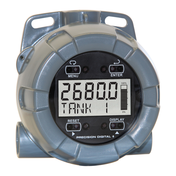
PD6700-0L1 Field-Mount Loop-Powered
Process Meter with Bargraph
Instruction Manual
• NEMA 4X, IP66 Loop-Powered Field-Mount Process Meter
• 4-20 mA Input with ±0.03% Accuracy
• 3.0 Volt Drop (6.0 Volt Drop with Backlight)
• Easy Field Scaling in Engineering Units without Applying an Input
• 0.6" (15.2 mm) 5 Digits Upper Display
• 0.4" (10.2 mm) 7 Alphanumeric Characters Lower Display
• Display Mountable at 0°, 90°, 180°, & 270°
• SafeTouch
Through-Window Button Programming
TM
• Display Input in Two Different Scales Simultaneously - Great for Level Applications
• 20-Segment Level Indicator Bargraph
• Open Collector Output Assignable to High or Low Alarm
• HART
®
Protocol Transparent
• Loop or External DC-Powered Backlight Standard
• Operating Temperature Range: -40 to 75°C (-40 to 167°F)
• Conformal Coated PCBs for Dust and Humidity Protection
• Password Protection
• 32-Point Linearization
• Wide Viewing Angle
• Flanges for Wall or Pipe Mounting
• Plastic NEMA 4X, IP66 Enclosure
• Three 3/4" NPT Threaded Conduit Openings (Two Plugs Installed)
• Stainless Steel Tag Available
• 3-Year Warranty
PRECISION DIGITAL CORPORATION
233 South Street • Hopkinton MA 01748 USA
Tel (800) 343-1001 • Fax (508) 655-8990
www.predig.com
Advertisement

Related Manuals for PRECISION DIGITAL vantageview Safe Touch PD6700-0L1


Summary of Contents for PRECISION DIGITAL vantageview Safe Touch PD6700-0L1
- Page 1 • Plastic NEMA 4X, IP66 Enclosure • Three 3/4" NPT Threaded Conduit Openings (Two Plugs Installed) • Stainless Steel Tag Available • 3-Year Warranty PRECISION DIGITAL CORPORATION 233 South Street • Hopkinton MA 01748 USA Tel (800) 343-1001 • Fax (508) 655-8990 www.predig.com...
- Page 2 4-20 mA loop or from a separate DC power Anyone using this product for such applications supply. does so at his/her own risk. Precision Digital The enclosure is provided with three threaded conduit Corporation shall not be held liable for damages holes and integrated pipe or wall mounting slotted resulting from such improper use.
- Page 3 PD6700-0L1 Field-Mount Loop-Powered Process Meter Instruction Manual Table of Contents Introduction ......................2 Ordering Information ................... 2 Specifications....................... 5 General ......................5 Input ........................5 Open Collector Output ..................5 Safety Information ....................6 Installation ......................6 Unpacking ......................6 Pre-Installed Conduit Plug ................
- Page 4 PD6700-0L1 Field-Mount Loop-Powered Process Meter Instruction Manual Table of Figures Figure 1. Enclosure Dimensions – Front View ............ 6 Figure 2. Enclosure Dimensions – Side Cross Section View ......6 Figure 3. Connector Board..................7 Figure 4. Connections without Backlight ............8 Figure 5.
- Page 5 PD6700-0L1 Field-Mount Loop-Powered Process Meter Instruction Manual Specifications Mounting May be mounted directly to conduit. Two slotted flanges for wall mounting or NPS Except where noted all specifications apply to operation at +25°C. 1½" to 2½" or DN 40 to 65 mm pipe mounting.
- Page 6 PD6700-0L1 Field-Mount Loop-Powered Process Meter Instruction Manual Safety Information Mounting The PD6700-0L1 has two slotted mounting flanges that may be used for pipe mounting or wall mounting. • Read complete instructions prior to installation Alternatively, the unit may be supported by the and operation of the meter.
- Page 7 PD6700-0L1 Field-Mount Loop-Powered Process Meter Instruction Manual Connections • Observe all safety regulations. Electrical wiring To access the connectors, remove the enclosure should be performed in accordance with all cover and unscrew the two captive screws that fasten agency requirements and applicable national, the display module.
- Page 8 PD6700-0L1 Field-Mount Loop-Powered Process Meter Instruction Manual External Acknowledge Connection Wiring Diagrams External acknowledge connections are made to two Signal connections are made to a four-terminal terminals labeled RESET. Connect to a contact closure connector mounted in the base of the enclosure per source such as a relay or a pushbutton as shown in Figure 3.
- Page 9 PD6700-0L1 Field-Mount Loop-Powered Process Meter Instruction Manual Setup and Programming SafeTouch Button Tips and Troubleshooting There is no need to recalibrate the meter when first The SafeTouch buttons are designed to filter normal received from the factory. Simply scale the meter to levels of ambient interference and to protect against display the process in engineering units.
- Page 10 PD6700-0L1 Field-Mount Loop-Powered Process Meter Instruction Manual Buttons and Display Menu Button • Press the Menu button to enter Programming Mode. • Press the Menu button during Programming Mode to return to the previous menu selections. • Hold the Menu button for 1.5 seconds at any time to exit Programming Mode and return to Run Mode.
- Page 11 PD6700-0L1 Field-Mount Loop-Powered Process Meter Instruction Manual Main Menu Display Functions & Main Menu Messages The main menu consists of the most commonly used The meter displays various functions and messages functions: Setup, Advanced, and Password. during setup, programming, and operation. The Press MENU button to enter Programming Mode then following table shows the main menu functions and press the Up Arrow button to scroll through the main...
- Page 12 PD6700-0L1 Field-Mount Loop-Powered Process Meter Instruction Manual Setting Numeric Values Setting Up the Meter (SETUP) The numeric values are set using the RIGHT and UP The Setup menu is used to select: arrow buttons. Press RIGHT arrow to select next digit Decimal point location and UP arrow to increment digit.
- Page 13 PD6700-0L1 Field-Mount Loop-Powered Process Meter Instruction Manual Scaling the Meter (SCaLe) Scaling the Tank Level Indicator (PERCENT) The 4-20 mA input can be scaled to display the process in engineering units. To scale the meter, The display includes a 20-segment tank level enter the value in milliamps (mA) for input 1, and then indicator.
- Page 14 PD6700-0L1 Field-Mount Loop-Powered Process Meter Instruction Manual Setting the Tag (TAG) Making Changes to a Password Protected Meter Any lower display setting that includes a tag will require the tag to be entered. If the meter is password protected, the meter will display the message LOCKED when the Menu button is pressed.
- Page 15 PD6700-0L1 Field-Mount Loop-Powered Process Meter Instruction Manual Advanced Features Menu (ADVANCE) To simplify the setup process, functions not needed for most applications are located in the Advanced Features Menu. Access the Advanced Features Menu by pressing ENTER at the ADVANCE menu in the Main Menu defined on page 11.
- Page 16 PD6700-0L1 Field-Mount Loop-Powered Process Meter Instruction Manual Advanced Features Menu & Display Messages The following table shows the Advanced features menu functions and messages in the order they appear in the menu. Display Parameter Action/Setting Display Parameter Action/Setting SAVE ? Save Save entered volume OUTPUT...
- Page 17 PD6700-0L1 Field-Mount Loop-Powered Process Meter Instruction Manual Alarm Output (OUTPUT) Input Signal Filter (FILTER) The PD6700-0L1 is equipped with an NPN open The noise filter is available for unusually noisy signals collector output that may be set up for high or low that cause an unstable process variable display.
- Page 18 PD6700-0L1 Field-Mount Loop-Powered Process Meter Instruction Manual Level Input Live Signal Calibration Notes: The signal source must have a full-scale (LVL CAL) accuracy of 0.002% or better between 4 and The meter can be calibrated using a current source 20 mA in order to maintain the specified instead of scaling.
- Page 19 PD6700-0L1 Field-Mount Loop-Powered Process Meter Instruction Manual Operation Front Panel Buttons Operation Reset Meter to Factory Defaults When the parameters have been changed in a way Button Symbol Description that is difficult to determine what’s happening, it might be better to start the setup process from the factory Press to Enter or Exit defaults.
- Page 20 PD6700-0L1 Field-Mount Loop-Powered Process Meter Instruction Manual Troubleshooting Factory Defaults & User Settings Due to the many features and functions of the meter, it’s possible that the setup of the meter does not The following table shows the factory setting for most agree with what an operator expects to see.
- Page 21 PD6700-0L1 Field-Mount Loop-Powered Process Meter Instruction Manual Quick User Interface Reference Pushbutton Function MENU Go to programming mode or leave programming. Hold for 5 seconds to enter Advanced Features menu directly. RIGHT Move to next digit. Arrow Go to previous menu or alphanumeric character selection.
- Page 22 PD6700-0L1 Field-Mount Loop-Powered Process Meter Instruction Manual Contact Precision Digital Technical Support Call: (800) 610-5239 or (508) 655-7300 Fax: (508) 655-8990 Email: support@predig.com Sales Support Call: (800) 343-1001 or (508) 655-7300 Fax: (508) 655-8990 Email: sales@predig.com Place Orders Email: orders@predig.com For the latest version of this manual please visit www.predig.com...
Need help?
Do you have a question about the vantageview Safe Touch PD6700-0L1 and is the answer not in the manual?
Questions and answers