Omron SmartSlice GRT1 Series Operation Manual
Slice i/o units
Hide thumbs
Also See for SmartSlice GRT1 Series:
- Operation manual (111 pages) ,
- Operation manual (365 pages) ,
- Operation manual (366 pages)
Table of Contents
Advertisement
Advertisement
Chapters
Table of Contents

Related Manuals for Omron SmartSlice GRT1 Series


Summary of Contents for Omron SmartSlice GRT1 Series
- Page 1 Cat. No. W455-E1-03 SmartSlice GRT1 Series Slice I/O Units OPERATION MANUAL...
- Page 2 SmartSlice GRT1 Series Slice I/O Units Operation Manual Revised July 2006...
- Page 4 OMRON. No patent liability is assumed with respect to the use of the information contained herein. Moreover, because OMRON is con- stantly striving to improve its high-quality products, the information contained in this manual is subject to change without notice.
-
Page 6: Table Of Contents
TABLE OF CONTENTS PRECAUTIONS ........Intended Audience ............General Precautions . - Page 7 TABLE OF CONTENTS SECTION 6 Counter Units and Positioning Unit ....133 Overview ..............Status Areas .
- Page 8 About this Manual: This manual describes the installation and operation of the Slice I/O Units and includes the sections described below. Please read this manual carefully and be sure you understand the information pro- vided before attempting to install or operate Slice I/O Units. Be sure to read the precautions pro- vided in the following section.
- Page 10 WHETHER SUCH CLAIM IS BASED ON CONTRACT, WARRANTY, NEGLIGENCE, OR STRICT LIABILITY. In no event shall the responsibility of OMRON for any act exceed the individual price of the product on which liability is asserted. IN NO EVENT SHALL OMRON BE RESPONSIBLE FOR WARRANTY, REPAIR, OR OTHER CLAIMS...
- Page 11 Application Considerations SUITABILITY FOR USE OMRON shall not be responsible for conformity with any standards, codes, or regulations that apply to the combination of products in the customer's application or use of the products. At the customer's request, OMRON will provide applicable third party certification documents identifying ratings and limitations of use that apply to the products.
- Page 12 Performance data given in this manual is provided as a guide for the user in determining suitability and does not constitute a warranty. It may represent the result of OMRON's test conditions, and the users must correlate it to actual application requirements. Actual performance is subject to the OMRON Warranty and Limitations of Liability.
-
Page 14: Precautions
PRECAUTIONS This section provides general precautions for installing and using the GRT1-series Slice I/O Units and related devices. The information contained in this section is important for the safe and reliable application of the Slice I/O Units. You must read this section and understand the information contained before attempting to set up or operate a Slice I/O Terminal. -
Page 15: Intended Audience
It is extremely important that a PLC and all PLC Units be used for the speci- fied purpose and under the specified conditions, especially in applications that can directly or indirectly affect human life. You must consult with your OMRON representative before applying a PLC system to the above mentioned applica- tions. -
Page 16: Operating Environment Precautions
Operating Environment Precautions • The PLC outputs may remain ON or OFF due to deposits on or burning of the output relays, or destruction of the output transistors. As a counter- measure for such problems, external safety measures must be provided to ensure safety in the system. -
Page 17: Application Precautions
Application Precautions !Caution The operating environment of the PLC System can have a large effect on the longevity and reliability of the system. Improper operating environments can lead to malfunction, failure, and other unforeseeable problems with the PLC System. Be sure that the operating environment is within the specified condi- tions at installation and remains within the specified conditions during the life of the system. -
Page 18: Ec Directives
EMC Directive OMRON devices that comply with EC Directives also conform to the related EMC standards, so that they can more easily be built in to other devices or the overall machine. The actual products have been checked for conformity to EMC standards. - Page 19 EC Directives the equipment or control panel on which the OMRON devices are installed. The customer must, therefore, perform the final check to confirm that devices and the overall machine conform to EMC standards. Low Voltage Directive Devices that operate at voltages from 50 to 1,000 VAC or 75 to 150 VDC must satisfy the appropriate safety requirements.
-
Page 20: Available Units And Features
SECTION 1 Available Units and Features This section describes the features of GRT1-series Slice I/O Units and lists the available Units. Slice I/O Terminal Introduction ........Features of the GRT1-series Slice I/O Units. -
Page 21: Slice I/O Terminal Introduction
Slice I/O Terminal Introduction Section 1-1 Slice I/O Terminal Introduction A Slice I/O Terminal is a building-block style remote I/O terminal made up of a Communications Unit and a number of Slice I/O Units, which each provide a small number of I/O points. The Slice I/O Units communicate with the host by remote I/O communications (cyclic communications) through the Communica- tions Unit. - Page 22 Section 1-2 Features of the GRT1-series Slice I/O Units Parameter Backup and Before replacing a Slice I/O Unit for maintenance, the parameter data set in Restore the I/O Unit can be backed up in the connected Communications Unit. The backed up parameter data is compared with the replacement I/O Unit’s data and the backed up data is restored to the replacement I/O Unit.
- Page 23 Features of the GRT1-series Slice I/O Units Section 1-2 Note The Contact Operation Counter and Total ON Time Monitor cannot be used at the same time for a single contact. Total ON Time Monitor This function can record the total ON time of devices connected to the Unit, such as sensors and relays.
- Page 24 Section 1-2 Features of the GRT1-series Slice I/O Units methods of the I/O device. Compensation is performed by applying linear con- version based on the points corresponding to 0% and 100%. Cumulative Counter A cumulated value that approximates the integral of analog input or output val- ues over time can be calculated and read.
-
Page 25: Available Units
Section 1-3 Available Units Available Units The following tables list the available GRT1-series Units, categorized by type. 1-3-1 Communications Units Type I/O points Model number Description DeviceNet Communications GRT1-DRT Interface Unit that con- Unit nects the DeviceNet Unit with the Slice I/O Units 1-3-2 General I/O Units... - Page 26 Available Units Section 1-3 Type I/O points Model number Description I/O Power Supply Unit GRT1-PD2 Can supply additional I/O power within the Slice I/O Terminal. End Unit GRT1-END An End Unit must be mounted to the end of the Slice I/O Terminal. 1-3-6 Connecting Cable Type...
- Page 27 Section 1-3 Available Units 1-3-7 Functions Supported by Slice I/O Units Function GRT1-series Slice I/O Unit General Units Counter Analog Units Units and Input Units Output Relay Output Input Output Positioning Units Units Units Units Unit Backup/Restore Supported Online Replacement Supported Automatic Baud Rate Recognition Supported Unit Conduction Time...
-
Page 28: Shared Specifications And Functions
SECTION 2 Shared Specifications and Functions This section describes the specifications and functions that are shared by all of the Slice I/O Units. Specifications Shared by the Units ....... . . 2-1-1 General Specifications . -
Page 29: Specifications Shared By The Units
Section 2-1 Specifications Shared by the Units Specifications Shared by the Units 2-1-1 General Specifications Item Specification ° −10 to 55 Ambient operating temperature C (with no icing or condensation) Ambient operating humidity 25% to 85% ° −25 to 65 Ambient storage temperature C (with no icing or condensation) Noise immunity... -
Page 30: Unit Numbers And I/O Allocations
Unit Numbers and I/O Allocations Section 2-2 ■ General I/O Units The following table shows the meaning of the yellow I/O indicators. Name Color Status Meaning Yellow Normal status I/O ON Not lit I/O OFF Unit Numbers and I/O Allocations 2-2-1 Unit Numbers of Slice I/O Units (Automatically Allocated) The numbers used to identify the Slice I/O Units in a Slice I/O Terminal are... - Page 31 Unit Numbers and I/O Allocations Section 2-2 2-2-2 I/O Allocation to the Slice I/O Terminal’s Master Unit The Slice I/O Terminal’s I/O data is allocated in the CPU Unit’s I/O memory and transferred through the Communications Unit and the Unit (such as a DeviceNet Unit) connected to the CPU Unit.
- Page 32 Section 2-2 Unit Numbers and I/O Allocations I/O Allocation I/O data is allocated to the I/O Units in the order that they are connected to the Example Communications Unit, regardless of the I/O Units’ models. Unless special allocation data settings are selected with the Communications Unit’s Pro- gramming Device, data is allocated from the first word starting with the Com- munications Unit’s status flags and then the leftmost I/O Unit’s data.
-
Page 33: Functions Shared By All Units
Functions Shared by all Units Section 2-3 Allocated Data Size Data type Data size I/O data When only the actual I/O data is allocated: 64 input words max. or 64 output words max. The GRT1-ID4(-1) and GRT1-OD4(-1) use 4 bits per Unit. - Page 34 Section 2-3 Functions Shared by all Units (2) The backup data will be erased along with the registered I/O configuration table if the power is turned OFF and back ON or if the Unit is restarted while DIP switch pin 1 (REGS) is turned OFF. (3) We recommend backing up the parameter data in case a Unit fails in the future.
- Page 35 Section 2-3 Functions Shared by all Units Note (1) Do not turn OFF the power or reset the Unit from the Configurator while data is being restored. The data will not be restored properly if the power is turned OFF or the Unit is reset. (2) When an I/O Unit has been replaced with the power ON and the new I/O Unit joins I/O communications, the new Unit will be compared to the pre- vious one and the parameter data restore operation will start automatical-...
- Page 36 Functions Shared by all Units Section 2-3 shocks. In addition, if external power is supplied to the terminal block for a Unit such as a Relay Output Unit, turn OFF that power supply before replacing the Unit. (4) Only replace one I/O Unit at a time. (5) Always replace the I/O Unit with the same model of I/O Unit.
- Page 37 Section 2-3 Functions Shared by all Units 2. Select the I/O Module Tab. 3. Click the Edit Button to display the Edit Unit Parameters Window. 4. Input the desired monitor value in the Unit Conduction Time field. 5. Click the Download Button, and then click the Reset Button to reset the Unit.
- Page 38 Section 2-3 Functions Shared by all Units 2-3-5 Unit Comments Function Overview The user can assign and record a name or comment for every Unit (up to 32 characters). The network Programming Device can be used to read and write these Unit names (comments).
- Page 39 Section 2-3 Functions Shared by all Units 3. Click the Edit Button to display the Edit Unit Parameters Window. 4. Input the desired name in the Comment field. 5. Click the Download Button, and then click the Reset Button to reset the Unit.
- Page 40 Functions Shared by all Units Section 2-3 Setting with a This example shows how to use the DeviceNet Configurator (version 2.43 or Programming Device higher) to set the device comments. 1,2,3... 1. Open the Network Configuration Window and double-click the desired Slice I/O Terminal’s icon or right-click the icon and select Parameters - Edit to display the Edit Device Parameters Window.
- Page 41 Functions Shared by all Units Section 2-3 2-3-7 Communications Error History Monitor Function Overview Information on communications error (communications error code, communi- cations power voltage when the error occurred) for the last four communica- tions errors can be recorded in the Unit. The network Programming Device can be used to read that communications error history.
- Page 42 Section 2-3 Functions Shared by all Units 2. Select the desired Slice I/O Unit from the list in the I/O Module Tab and click the View Button. 3. Select the Error History Tab in the Maintenance Information Window. The communications error history for the last four errors will be displayed, as shown in the following window.
- Page 43 Functions Shared by all Units Section 2-3 2-3-8 Last Maintenance Date Function Overview This function can be used to write the date on which maintenance was last performed to the Unit. This means that the timing for future maintenance can be judged more easily.
-
Page 44: Installation And Wiring
SECTION 3 Installation and Wiring This section provides information on installing and wiring the Slice I/O Units. Installation........... . 3-1-1 Connecting the Communications Unit and Slice I/O Unit . -
Page 45: Installation
Section 3-1 Installation Installation The Slice I/O Terminal is installed and set up as a network Slave. The Com- munications Unit’s communications connector connects to the Master Unit through a communications cable. Up to 64 Slice I/O Units can be connected to one Communications Unit. Master Slide Slice I/O Units in from the front to install. -
Page 46: Connecting Additional Slice I/O Units
Installation Section 3-1 3-1-2 Connecting Additional Slice I/O Units Connect additional Slice I/O Units by aligning the sides of the Units and slid- ing in the next Unit from the front. Up to 64 Slice I/O Units can be connected to one Communications Unit. -
Page 47: Installation On A Din Track
Section 3-1 Installation Connecting the End A GRT1-END End Unit must be connected to the end of the Slice I/O Termi- Unit nal. GRT1-END End Unit Note When connecting Units, always align the guide tracks on the top and bottom of the Units and be sure that they join properly as you slide the Unit toward the DIN Track. - Page 48 Section 3-1 Installation Slice I/O Terminal There is no particular restriction on the Slice I/O Terminal’s orientation. The Orientation Terminal can be mounted in any of the following 6 directions. Installing a Unit Press the Units onto the DIN Track firmly from the front. Press the Unit firmly until it clicks, indicating that the Unit’s DIN Track Mounting Hooks have locked onto the DIN Track.
- Page 49 Section 3-1 Installation Removing an Entire Unit Including the Base Block 1,2,3... 1. Remove the main block of the Unit on the right side of the Slice I/O Unit actually being replaced. 2. Release the Mounting Hook locks of the Unit being replaced. (The hooks attach the Unit to the top and bottom of the DIN Track.) 3.
-
Page 50: Power Supply Wiring
Section 3-2 Power Supply Wiring Installing the End Always secure the Slice I/O Terminal on the DIN Track by installing End Plates Plates on both sides of the Terminal. First hook the bottom of the End Plate on the bottom edge of the DIN Track (1), attach the top of the End Plate, and pull the End Plate down onto the top edge of the DIN Track (2). -
Page 51: Wiring Methods
Section 3-2 Power Supply Wiring Power Consumption of Slice I/O Units For details on the power consumption of the various Slice I/O Units, refer to Appendix C Power Consumption and Weight Tables. Note When dividing the power supply, always wire (supply) the power from the same power supply. - Page 52 Section 3-2 Power Supply Wiring Holes for wires (pin terminals) Release button Press the release button with a screwdriver and pull out the wire (pin terminal). These terminals supply power to both the Communications Unit's internal 24 VDC circuits and the connected Slice I/O Units' internal circuits.
-
Page 53: Connecting Turnback Cables
Use a SELV power supply with overcurrent protection. Supplies A SELV power supply has redundant or increased insulation between the I/O, an output voltage of 30 Vr.m.s and a 42.4-V peak or maximum of 60 VDC. Recommended power supply: S82K-10024 (OMRON) or S82J-10024D (OMRON) Recommended Wire Type... - Page 54 Section 3-3 Connecting Turnback Cables GRT1-TBR Turnback Unit GCN2-100 Turnback Cable GRT1-TBL Turnback Unit Insert the cable's connector fully until it clicks, which indicates that the connector's top and bottom latches have locked.
- Page 55 Section 3-3 Connecting Turnback Cables...
-
Page 56: General-Purpose Slice I/O Units
SECTION 4 General-purpose Slice I/O Units This section provides the specifications and shows the components, terminal arrangements, wiring diagrams, and dimensions for the General-purpose Slice I/O Units. Specifications Shared by the Units ....... . . Status Area . -
Page 57: Specifications Shared By The Units
Section 4-1 Specifications Shared by the Units Specifications Shared by the Units The following tables show the specifications common to all of the General- purpose Slice I/O Units. For details on other specifications, refer to the pages describing the individual Slice I/O Unit. Specifications Item Specification... -
Page 58: Status Area
Section 4-2 Status Area Status Area 4-2-1 Status Areas of General-purpose Slice I/O Units The General-purpose Slice I/O Units have two status areas. Each Unit’s sta- tus flags are turned ON and OFF based on the threshold/monitor values set for the function in that Unit. A flag in the Communications Unit will be turned ON only when the corresponding flag has been turned ON in one of those sta- tus areas. - Page 59 Section 4-2 Status Area Alarm Status Area The Slice I/O Unit’s alarm status area contains the following 16 bits. These flags indicate non-fatal errors in the Unit. When any of these flags goes ON, bit 3 of the Communications Unit’s status flags is turned ON and that informa- tion is transmitted to the Master.
-
Page 60: I/O Wiring
I/O Wiring Section 4-3 I/O Wiring 4-3-1 Wiring to the Screwless Clamping Terminal Block All of the GRT1-series Slice I/O Units can be wired with screwless clamp ter- minal blocks, which do not require screws to be tightened. When connecting a sensor or an external device, always crimp pin terminals to the cable of the sensor or device. -
Page 61: Functions Of General-Purpose Slice I/O Units
Functions of General-purpose Slice I/O Units Section 4-4 Functions of General-purpose Slice I/O Units 4-4-1 I/O Power Supply Monitor Function Overview This function is used to detect whether the I/O power is ON. When the I/O power supply is turned OFF, the Basic Unit I/O Power Supply Status Flag or Expansion Unit I/O Power Supply Status Flag in the Status Area is turned ON. -
Page 62: Input Filter (Input Units Only)
Section 4-4 Functions of General-purpose Slice I/O Units 4-4-2 Input Filter (Input Units Only) Function Overview Input values can be read several times during a set interval so that the input value is enabled only when the value of all samples are the same. The input filter is applied to all of the inputs of the Unit. - Page 63 Functions of General-purpose Slice I/O Units Section 4-4 Setting with a This example shows how to use the DeviceNet Configurator (version 2.43 or Programming Device higher) to set the input filter. 1,2,3... 1. Open the Network Configuration Window and double-click the desired Slice I/O Terminal’s icon or right-click the icon and select Parameters - Edit to display the Edit Device Parameters Window.
-
Page 64: Sensor Power On Delay (Input Units Only)
Section 4-4 Functions of General-purpose Slice I/O Units 4-4-3 Sensor Power ON Delay (Input Units Only) Function Overview When the I/O power has gone OFF, this function blocks inputs for the first 100 ms after the I/O power is turned back ON. The power ON delay allows the sensor power supply to stabilize and prevents false input signals caused by inrush current at startup. -
Page 65: Contact Operation Counter
Section 4-4 Functions of General-purpose Slice I/O Units 4-4-4 Contact Operation Counter Function Overview The Contact Operation Counter is used to count the number of times each input or output contact has changed from OFF to ON (maximum resolution 50 Hz) and record the total value calculated in the Unit. - Page 66 Functions of General-purpose Slice I/O Units Section 4-4 Setting with a This example shows how to use the DeviceNet Configurator (version 2.43 or Programming Device higher) to set the Contact Operation Counter function. 1,2,3... 1. Open the Network Configuration Window and double-click the desired Slice I/O Terminal’s icon or right-click the icon and select Parameters - Edit to display the Edit Device Parameters Window.
-
Page 67: Total On Time Monitor
Section 4-4 Functions of General-purpose Slice I/O Units 4-4-5 Total ON Time Monitor Function Overview The total ON time for each I/O contact can be calculated (unit: s) and recorded in the Unit. A monitor value can be set in the Unit, and when the total I/O contact ON time reaches the monitor value, the Connected Device Mainte- nance Flag in the Status Area is turned ON. - Page 68 Section 4-4 Functions of General-purpose Slice I/O Units In Figure 2, the actual ON time is 0.5 s × 3 = 1.5 s. The reading will be taken twice during this ON time, so the total ON time will be measured as 2 s. Reading taken approximately every second.
- Page 69 Section 4-4 Functions of General-purpose Slice I/O Units 3. Select the desired device and double-click the I/O Comment Column to display the following window. Select Time under Detection Mode, enter a monitor value in the Value field, and then click the OK Button. 4.
-
Page 70: Operation Time Monitor
Section 4-4 Functions of General-purpose Slice I/O Units 4-4-6 Operation Time Monitor Function Overview This function can measure and monitor the time between the ON/OFF transi- tions of two bits. The Unit’s starting and ending bits can be selected freely. The trigger edge (ON →... -
Page 71: Output Hold/Clear Setting
Section 4-4 Functions of General-purpose Slice I/O Units 4. After checking that the setting for the monitor value is reflected in the Edit Unit Parameters Window, select the General Tab, click the Download But- ton, and then click the Reset Button. 5. -
Page 72: Maintenance Information Window
Section 4-5 Maintenance Information Window 5. After checking that the settings are reflected in the Edit Unit Parameters Window, click the General Tab, click the Download Button, and then click the Reset Button. 6. Click the OK Button. Maintenance Information Window This section describes the Maintenance Information Window, which can be used to check the status of the General-purpose Slice I/O Units. - Page 73 Section 4-5 Maintenance Information Window Tabs in the Maintenance Information Window General Tab Status check boxes (Status flags) Item Description Comment Displays up to 32 characters of text set as the Unit comment. Last Maintenance Displays the last maintenance date that was set. Date Unit Conduction Displays the total time that the Unit has been ON (cumulative...
- Page 74 Section 4-5 Maintenance Information Window OUT Tab Output terminals are listed in numerical order. Item Description Comment Displays up to 32 characters of text set as the output comment for each output. Maintenance Displays the maintenance counter for each output. If the main- Counter tenance counter exceeds the threshold value, a warning icon will be displayed on the left side of the output’s No.
- Page 75 Section 4-5 Maintenance Information Window Item Description Comment Displays up to 32 characters of text set as the input comment for each input. Maintenance Displays the maintenance counter for each input. If the mainte- Counter nance counter exceeds the threshold value, a warning icon will be displayed on the left side of the input’s No.
-
Page 76: General-Purpose Slice I/O Units
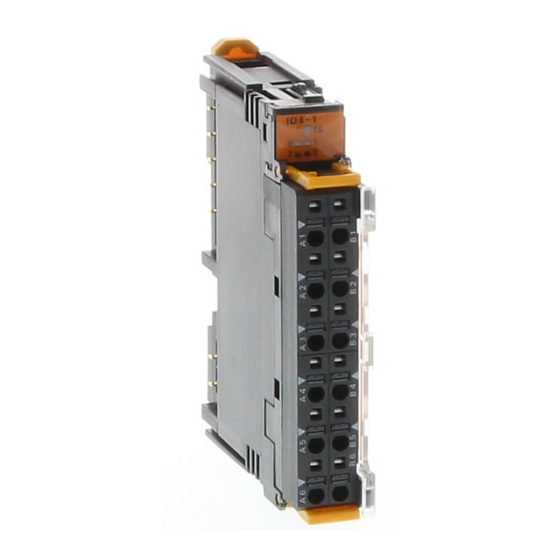
Section 4-6 General-purpose Slice I/O Units Error History Tab Displays the most recent errors that have occurred. Item Description Content Displays the contents of the communications errors that have occurred. Unit Conduction Displays the total time that the network power supply had been Time ON when the error occurred. - Page 77 Section 4-6 General-purpose Slice I/O Units Component Names and Functions (Same for GRT1-ID4 LED indicators Indicate the Unit's status. and GRT1-ID4-1) Test pin Release button Terminal insertion hole Terminal Block Internal Circuits GRT1-ID4 (NPN) Terminal block Base block Main block I/O LED Internal circuits Internal circuits...
- Page 78 Section 4-6 General-purpose Slice I/O Units GRT1-ID4-1 (PNP) Base block Terminal block Main block I/O LED Internal circuits Internal circuits Wiring GRT1-ID4 (NPN) Black (white) Brown (white) Blue (black) Brown (red) Blue (black) 2-wire sensor (such as a limit switch) 3-wire sensor with NPN output (photoelectric or proximity sensor) GRT1-ID4-1 (PNP)
-
Page 79: Output Units With Four Transistor Outputs: Grt1-Od4 (Npn) And Grt1-Od4-1 (Pnp)
Section 4-6 General-purpose Slice I/O Units Dimensions (Same for GRT1-ID4 (88.5) and GRT1-ID4-1) 14.1 74.4 (74.4) OMRON 4-6-2 Output Units with Four Transistor Outputs: GRT1-OD4 (NPN) and GRT1-OD4-1 (PNP) Output Specifications Item Specification Model GRT1-OD4 GRT1-OD4-1 Internal I/O common NPN Number of I/O points 4 outputs Rated output current 0.5 A/point... - Page 80 Section 4-6 General-purpose Slice I/O Units Component Names and Functions (Same for GRT1-OD4 LED indicators Indicate the Unit's status. and GRT1-OD4-1) Test pin Release button Terminal insertion hole Terminal Block Internal Circuits GRT1-OD4 (NPN) Main block Terminal block Base block I/O LED Internal circuits Voltage...
- Page 81 Section 4-6 General-purpose Slice I/O Units GRT1-OD4-1 (PNP) Main block Terminal block Base block I/O LED Internal circuits Voltage step-down Internal circuits Wiring GRT1-OD4 (NPN) Solenoid, valve, etc. GRT1-OD4-1 (PNP) Solenoid, valve, etc.
-
Page 82: Relay Output Unit With Two Relay Outputs: Grt1-Ros2
Section 4-6 General-purpose Slice I/O Units Dimensions (Same for GRT1-OD4 (88.5) and GRT1-OD4-1) 14.1 74.4 (74.4) OMRON 4-6-3 Relay Output Unit with Two Relay Outputs: GRT1-ROS2 Common Specifications Item Specifications Communications power supply 24 V DC (20.4 to 26.4 V DC) - Page 83 Section 4-6 General-purpose Slice I/O Units Relay Life Expectancy Item Specifications Mechanical life expectancy 20,000,000 times min. Electrical life expectancy 100,000 times min. Component Names and Functions LED indicators ROS2 Indicate the Unit's status. Test pin Release button Terminal insertion hole Terminal Block Internal Circuits Base block...
- Page 84 Section 4-6 General-purpose Slice I/O Units Wiring AC power supply (or DC power supply) Load AC power supply (or DC power supply) Load Dimensions (88.5) 14.1 74.4 (74.4) OMRON...
- Page 85 Section 4-6 General-purpose Slice I/O Units...
-
Page 86: Analog Units
SECTION 5 Analog Units This section provides the information required to operate Analog Input Units and Analog Output Units, including functions, status areas, windows, specifications, wiring, data allocation, and settings. Overview of Analog Units ........5-1-1 Analog Units. -
Page 87: Overview Of Analog Units
Section 5-1 Overview of Analog Units Overview of Analog Units This section provides an overview of Analog Units, including details on func- tions and setting methods for each Unit. 5-1-1 Analog Units In addition to the functions common to the GRT1 Series (backup, restore, online conversion, etc.), other functions specific to Analog Units (scaling, peak/bottom hold, etc.) are available. - Page 88 Section 5-1 Overview of Analog Units Unit GRT1 Series DRT2 Series Model GRT1-AD2 DRT2-AD04 Baud rate setting No setting required. Automatically detected: Uses baud rate set for Master Unit. Moving average Supported. (Set using Setting Tool.) Supported. (Set using DeviceNet Con- figurator.) Off-wire detection Supported.
-
Page 89: List Of Data Processing Functions
Section 5-1 Overview of Analog Units 5-1-3 List of Data Processing Functions The following tables list the data processing functions that can be used with Analog Units. Refer to 5-4-3 Functions and Settings for details on functions and setting methods. GRT1-AD2 Analog Input Units Function Details... -
Page 90: Data Processing Flowcharts (Analog Input Units)
Overview of Analog Units Section 5-1 5-1-4 Data Processing Flowcharts (Analog Input Units) Analog Input Value The following math operations can be performed on the external analog input value. The values obtained after processing (analog input values) can be allo- cated as I/O in the Master. -
Page 91: I/O Data
Overview of Analog Units Section 5-1 Flow of Data in Analog Input Units Moving average, scal- Six types of data ing enabled/disabled Select one of the six types of data and allocate as analog data. Analog input value 1 Peak value 2 Bottom value 3 Analog Data Top value 4... -
Page 92: Status Areas
Section 5-2 Status Areas Output Data I/O data Details Hold Flags (1 output byte) Used with each of the hold functions (peak, bottom, top, and valley) to control the execu- tion timing of hold functions from the Master. GRT1-DA2@ Analog Analog Output Units support one type output data. - Page 93 Status Areas Section 5-2 Contents Description Cumulative Counter Flag Turns ON when the cumulative value exceeds the monitoring set value. OFF: Within range (below monitoring set value) ON: Out of range (at or above monitoring set value) Reserved. Reserved. Reserved. Reserved.
-
Page 94: Maintenance Information Window
Section 5-3 Maintenance Information Window Contents Description Cumulative Counter Flag Turns ON when the cumulative value exceeds the monitoring set value. OFF: Within range (below monitoring set value) ON: Out of range (at or above monitoring set value) Reserved. Reserved. Reserved. -
Page 95: Checking Maintenance Information
Section 5-3 Maintenance Information Window 5-3-1 Checking Maintenance Information There are two ways to check maintenance information. One way is to right- click in the Main Window of the Setting Tool and select Maintenance Infor- mation. The other way is to double-click the Unit in the Maintenance Mode Window, click the I/O Module Tab, select the desired Unit, and click the View Button to display the Maintenance Information Window of the I/O Unit. -
Page 96: Analog Input Units
Analog Input Units Section 5-4 Display Area Item Description I/O Comment Displays up to 32 characters of text as a comment. A separate comment can be set for each input. Last Maintenance Displays the last maintenance date and time. (All models.) Date Present Value Displays the present analog value. - Page 97 Section 5-4 Analog Input Units Item Specifications Storage temperature –20 to 65°C (with no icing or condensation) Mounting 35-mm DIN Track mounting Performance Specifications Item Specifications Voltage input Current input Input points 2 points (Inputs 0 to 1) Input signal range 0 to 5 V 0 to 20 mA 1 to 5 V...
- Page 98 Section 5-4 Analog Input Units Names and Functions of Parts LED Indicator Displays Unit status. Terminal Test Pins Block Release Buttons Terminal Insertion Holes DIP Switch Used to set input range. Setting the Input Range Setting with the DIP The input signal range can be set using the DIP switch or the Setting Tool. Switch Each pin is set according to the following table.
- Page 99 Section 5-4 Analog Input Units Input Range Settings ■ Inputs 0 and 1 (Shared Setting) Input range Pin 1 Pin 2 Pin 3 0 to 5 V 1 to 5 V 0 to 10 V –10 to 10 V 4 to 20 mA 0 to 20 mA Cannot set for other ranges.
- Page 100 Section 5-4 Analog Input Units Internal Circuits 510 kΩ − 510 kΩ SHTA 250 Ω SHTB Wiring Connect the terminals of the Analog Input Unit for each Input Unit according to the following diagrams, depending on whether a voltage input or a current input is being used.
- Page 101 Section 5-4 Analog Input Units ■ Input Range:1 to 5 V The voltage range 1 to 5 V corresponds to 0000 to 1770 hex (0 to 6,000). The convertible data range is FED4 to 189C hex ( 300 to 6,300). If the input volt- –...
- Page 102 Section 5-4 Analog Input Units ■ Input Range: 0 to 20 mA The current range 0 to 20 mA corresponds to 0000 to 1770 hex (0 to 6,000). The convertible data range is FED4 to 189C hex ( 300 to 6,300). Negative –...
-
Page 103: I/O Data Allocation Methods
Analog Input Units Dimensions (88.5) 14.1 74.4 (74.4) OMRON 5-4-2 I/O Data Allocation Methods Selecting I/O Data to Use one of the following methods to select data for allocating in the Communi- be Allocated cations Unit and then perform remote I/O communications. - Page 104 Section 5-4 Analog Input Units Setting Tool Procedure (Example: DeviceNet Configurator) 1,2,3... 1. In the Network Configuration Window of the Slice I/O Terminal, double- click the icon of the Slice I/O Terminal that is to be set. Alternatively, right- click the icon and select Parameters - Edit. The Edit Device Parameters Window will be displayed.
- Page 105 Section 5-4 Analog Input Units 4. Click the General Tab and select the desired I/O data from the pull-down menu under the Default Connection Path (In) Field. In the following exam- ple Analog Data is selected. 5. Return to the General Tab Page, click the Download Button and then click the Reset Button to reset the Unit.
- Page 106 Section 5-4 Analog Input Units 3. Open the tab page for the input for which analog data is to be selected, and select from the pull-down list the type of data to be allocated to Analog Da- 4. Return to the General Tab Page, click the Download Button and then click the Reset Button to reset the Unit.
- Page 107 Section 5-4 Analog Input Units The details of each byte are shown in the following table. Byte Abbreviation Name Details V_STx Valley Detection Tim- Turns ON when a valley is ing Flag detected by the valley hold function and then turns OFF after the one-shot time has elapsed.
-
Page 108: Functions And Settings
Section 5-4 Analog Input Units Abbrevi- Name Details ation V_STx Top/val- Valley Detec- Used with the valley hold func- ley detec- tion Timing Flag tion. tion Turns ON when a valley is timing detected, and turns OFF after the one-shot time has lapsed. T_STx Top Detection Used with the top hold function. - Page 109 Section 5-4 Analog Input Units conversion cycle speed is increased. For details on conversion cycle time, refer to 5-4-4 Calculating the Conversion Cycle. Conversion points Details 2 points (default) Converting Inputs 0 to 1. GRT1-AD2 All used. 1 point Converting Input 0. GRT1-AD2 Input 0 only used.
- Page 110 Section 5-4 Analog Input Units 2. Click the I/O Module Tab. 3. Click the Edit Button in the I/O Module Tab Page. The Edit Unit Parame- ters Window will be displayed. 4. Click the General Tab and select the number of conversion points from the pull-down menu in the Available Channel Field.
- Page 111 Section 5-4 Analog Input Units Moving Average This function calculates the average value (moving average) of the previous Processing eight inputs, and uses the resulting value as conversion data. When the input value fluctuates frequently, averaging can be used to produce a stable input value, as shown in the following diagram.
- Page 112 Section 5-4 Analog Input Units for ladder programming in the Master to perform math operations. The follow- ing two methods of input scaling can be used. Default Scaling Analog input values (count values) are converted to the original voltage and µ...
- Page 113 Section 5-4 Analog Input Units Upper limit 7FFE 100% scaling value Scaled line 0% scaling Offset value (–28,000 to 28,000) Input signal range 100% Setting Tool Procedure (Example: DeviceNet Configurator) 1,2,3... 1. In the Network Configuration Window of the Slice I/O Terminal, double- click the icon of the Analog Input Unit that is to be set.
- Page 114 Section 5-4 Analog Input Units 5. Click the Scaling Tab, and select either Default Scaling or User Scaling. The following example shows when Default Scaling is selected. 6. For user scaling, set the 0% value in the Scaling point 1 Field, and set the 100% value in the Scaling point 2 Field.
- Page 115 Section 5-4 Analog Input Units 7. For offset compensation, set the offset value in the Scaling Offset Field. Also select either Default Scaling or User Scaling in the Scaling Type Field. 8. Return to the General Tab Page, click the Download Button, and then click the Reset Button to reset the Unit.
- Page 116 Section 5-4 Analog Input Units turned ON may be the data from when the Hold Flag was OFF. To collect peak/bottom hold data using the Hold Flag at the Master, configure a ladder program that considers the transmission delay when the Hold Flag is turned ON, then enables the peak/bottom hold values after a fixed time interval.
- Page 117 Section 5-4 Analog Input Units 5. To allocate the Hold Flags (output) in the default connection path, click the General Tab and select Holding Value from the pull-down menu in the De- fault Connection Path (Out) Field. 6. Click the Download Button and then click the Reset Button to reset the Unit.
- Page 118 Section 5-4 Analog Input Units ■ Example of Valley Hold Valley hold value Analog input value Last value is held. Hold value Hold Flag Hold function starts Hold function stops Top/Valley Detection Timing Flag One-shot time Note 1. A delay in network transmission time will occur from the time the Hold Flag turns ON (or OFF) in the Master’s ladder program until notification of the flag’s status is actually sent to the Unit.
- Page 119 Section 5-4 Analog Input Units 4. Select the tab page for the input where top/valley hold is to be set, and se- lect the Top/Valley Hold Check Option in the Function Choice Area. 5. To allocate the Hold Flag (output) in the default connection path, click the General Tab, and select Holding Value from the pull-down menu in the Default Connection Path (Out) Field.
- Page 120 Section 5-4 Analog Input Units value. This will cause the start of data holding to be delayed after the actual top or valley value occurs, as shown in the following diagram. ■ Timing for Setting Data Analog input value Set hysteresis value x 2 Valley hold value Top/Valley Detection Timing Flag...
- Page 121 Section 5-4 Analog Input Units One-shot Time Setting 1,2,3... 1. Input the desired value in the SHOT Off Delay Field of the Top/Valley Tab Page in the Function Choice Area. 2. Return to the General Tab Page, click the Download Button, and then click the Reset Button to reset the Unit.
- Page 122 Section 5-4 Analog Input Units regarded as the rate of change. To prevent this occurring, use moving average processing, which will set a longer sampling cycle. Desired gradient Fluctuation in analog value Short sampling cycle Long sampling cycle Setting Tool Procedure (Example: DeviceNet Configurator) 1,2,3...
- Page 123 Section 5-4 Analog Input Units 5. To set the sampling cycle, click the Rate of Change Tab and input the de- sired value for the sampling cycle in the Sampling Rate Field. 6. Return to the General Tab Page, click the Download Button, and then click the Reset Button to reset the Unit.
- Page 124 Section 5-4 Analog Input Units Setting Hysteresis The Comparator Result Flag turns OFF when the value is lower than the hys- teresis width (H or HH alarm occurs) or exceeds it (L or LL alarm occurs), as shown in the following diagram. If the analog value fluctuates around the threshold, and the flag repeatedly turns ON or OFF, setting hysteresis will sta- bilize the flag operation.
- Page 125 Section 5-4 Analog Input Units 4. Select the tab page for the input where the comparator function is to be set, and select the Comparator Check Option in the Function Choice Area. 5. Click the Comparator Tab and set each of the alarm values. The example here shows the setting for Alarm Trip Point High (HH).
- Page 126 Section 5-4 Analog Input Units 6. To set the hysteresis value, input the desired value in the Hysteresis Field. Note The hysteresis value set for the comparator function is also used by the top/ valley hold function. 7. To set the OFF delay function, input the desired value in the Comparator Off Delay Field.
- Page 127 Section 5-4 Analog Input Units Off-wire Detection When a disconnection occurs in an analog input line (voltage input or current input), the Off-wire Detection Flag turns ON for each input that is enabled in the number of AD conversion points. The Off-wire Detection Flags are included in the Analog Status Flags.
- Page 128 Section 5-4 Analog Input Units 4. Select the tab page for the input to be adjusted, and click the Adjustment Button. (At the same time set the input range again.) 5. Input the voltage (or current) transmitted from the connected device to the Unit’s input terminal that is equivalent to the 100% value.
- Page 129 Section 5-4 Analog Input Units 8. Click the Fix lower adjusting Value Button, and input the adjusted value. 9. To return an adjusted value to the default setting, click the Default Setting Button. 10. Close the Adjustment Window, return to the General Tab Page, click the Download Button, and then click the Reset Button to reset the Unit.
- Page 130 Analog Input Units Section 5-4 DRT2-AD2 Unit Divisions Hour 3.6 s (1/1,000 hour) Minute 60 ms (1/1,000 minute) Setting Tool Procedure (Example: DeviceNet Configurator) 1,2,3... 1. In the Network Configuration Window of the Slice I/O Terminal, double- click the icon of the Slice I/O Terminal that is to be set. Alternatively, right- click the icon and select Parameters - Edit.
- Page 131 Analog Input Units Section 5-4 5. To set the counter unit, click the Cumulated Count Tab and select Hour or Minute from the pull-down menu in the Cumulated Timer Field. 6. To set the monitor value, click the Cumulated Count Tab, and input the de- sired value in the Threshold Cumulated Counter Field.
- Page 132 Section 5-4 Analog Input Units Last Maintenance The last maintenance date can be set in the Unit separately for the Unit and Date the connected devices. It enables the user to easily determine the next main- tenance date. The date can be set using the Setting Tool. Setting Tool Procedure (Example: DeviceNet Configurator) ■...
-
Page 133: Calculating The Conversion Cycle
Analog Input Units Section 5-4 2. Click the tab page for the input that is connected to a connecting device requiring the last maintenance date to be set. Select the applicable date from the pull-down menu in the Last Maintenance Date Field. (To enter the current date, select Today, which is at the bottom of the pull-down menu.) 3. -
Page 134: Analog Output Units
Section 5-5 Analog Output Units The following table shows the additional time required for each function (unit: ms). Math operation Additional time for each point Moving average 0.045 Scaling 0.055 Peak/bottom hold 0.025 Top/valley hold 0.070 Comparator 0.065 Rate of change 0.030 Cumulative counter 0.035... - Page 135 Section 5-5 Analog Output Units Item Specifications GRT1-DA2V Voltage output GRT1-DA2C Current output DA conversion data –10 to 10 V range: F448 to 0BB8 hex full scale (–3,000 to 3,000) Other ranges: 0000 to 1770 hex full scale (0 to 6,000) ±...
- Page 136 Analog Output Units Section 5-5 Output range Pin 1 Pin 2 Pin 3 0 to 5 V (Factory set- Fixed at OFF. ting) 1 to 5 V 0 to 10 V –10 to 10 V Note 1. Always set pin 4 to ON if the DIP switch is used to set the range. If this pin is OFF, the DIP switch settings will not be enabled.
- Page 137 Section 5-5 Analog Output Units 5. Click the Output Range Field, and select the desired range. 6. Return to the General Tab Page, click the Download Button, and then click the Reset Button to reset the Unit. 7. Click the OK Button to exit. Internal Circuits GRT1-DA2C GRT1-DA2V...
- Page 138 Section 5-5 Analog Output Units Output Range and The digital values that are output are converted to analog data according to Conversion Data the output range used, as shown below. When the value exceeds the output range, the DA conversion data is fixed at the High Limit or Low Limit set value. Output Range: 0 to 5 V The values 0000 to 1770 hex (0 to 6,000) correspond to the voltage range 0 to 5 V.
- Page 139 Section 5-5 Analog Output Units Voltage 11 V 10 V F31C F448 (−3300) (−3000) 0000 (0) 8000 Conversion data Hexadecimal (decimal) 0BB8 0CE4 7FFF (3000) (3300) −10 V −11 V Output Range: 4 to 20 mA The values 0000 to 1770 hex (0 to 6,000) correspond to the current range 4 to 20 mA.
-
Page 140: I/O Data And Allocation Methods
Dimensions (88.5) 14.1 74.4 (74.4) OMRON 5-5-2 I/O Data and Allocation Methods When the Analog Output Unit’s default settings are used, output data is allo- cated. No special settings are required. Two words (four bytes) of output data are allocated as two’s complement. - Page 141 Analog Output Units Section 5-5 User Scaling User scaling allows analog output values to be scaled to user-defined values. The conversion values for 100% and 0% are set using the Setting Tool. Input 0 to 5 V 0 to 10 V 1 to 5 V –10 to 0 to 20...
- Page 142 Section 5-5 Analog Output Units Setting Tool Procedure (Example: DeviceNet Configurator) 1,2,3... 1. In the Network Configuration Window of the Slice I/O Terminal, double- click the icon of the Slice I/O Terminal that is to be set. Alternatively, right- click the icon and select Parameters - Edit. The Edit Device Parameters Window will be displayed.
- Page 143 Analog Output Units Section 5-5 5. To select the scaling type, click the Scaling Tab, and select either Default Scaling or User Scaling. The following example shows when User Scal- ing is selected. 6. For user scaling, set the 0% value in the Scaling point 1 Field, and set the 100% value in the Scaling point 2 Field.
- Page 144 Section 5-5 Analog Output Units 7. For offset compensation, set the offset value in the Scaling Offset Field. Also select either Default Scaling or User Scaling in the Scaling Type Field. 8. Return to the General Tab Page, click the Download Button, and then click the Reset Button to reset the Unit.
- Page 145 Section 5-5 Analog Output Units Output range Low Limit High Limit –10 to 10 V –11 to –9.0 V 9.0 to 11 V 4 to 20 mA 3.2 to 4.8 mA 19.2 to 20.8 mA 0 to 20 mA 0.2 to 1.0 mA 19 to 21 mA Setting Tool Procedure (Example: DeviceNet Configurator) 1,2,3...
- Page 146 Analog Output Units Section 5-5 6. Adjust the analog value that is output from the terminal using the Low Limit slide bar, as shown in the following window. Repeat adjustments until the correct 0% value is output from the output device. After compensation is completed, click the Fix lower adjusting Value Button.
- Page 147 Section 5-5 Analog Output Units Note If the High Limit adjustment is not performed for the 100% value, a discrep- ancy will occur when the Low Limit is adjusted, so always adjust the Low Limit of Output Units before adjusting the High Limit. Cumulative Counter The cumulative counter calculates an approximation to the integral of analog output values over time.
- Page 148 Section 5-5 Analog Output Units 4. Select the tab page for the output where the cumulated counter is to be set, and select the Cumulated Count Check Option in the Function Choice Ar- 5. To set the counter unit, click the Cumulated Count Tab and select Hour or Minute from the pull-down menu in the Cumulated Timer Field.
- Page 149 Section 5-5 Analog Output Units 6. To set the monitor value, click the Cumulated Count Tab, and input the de- sired value in the Threshold Cumulated Counter Field. 7. Return to the General Tab Page, click the Download Button, and then click the Reset Button to reset the Unit.
- Page 150 Section 5-5 Analog Output Units Setting Tool Procedure (Example: DeviceNet Configurator) 1,2,3... 1. In the Network Configuration Window of the Slice I/O Terminal, double- click the icon of the Slice I/O Terminal that is to be set. Alternatively, right- click the icon and select Parameters - Edit. The Edit Device Parameters Window will be displayed.
- Page 151 Section 5-5 Analog Output Units...
- Page 152 SECTION 6 Counter Units and Positioning Unit This section provides information required to operate Counter Units and Positioning Units, including functions, status areas, windows, specifications, wiring, I/O data assignments, and settings. Overview ........... . . 6-1-1 Counter Units and Positioning Unit .
-
Page 153: Overview
Section 6-1 Overview Overview This section provides an overview of the GRT1-CT1 and GRT1-CT1-1 Counter Units and the GRT1-CP1-L Positioning Unit. 6-1-1 Counter Units and Positioning Unit The GRT1-CT1(-1) Counter Units and GRT1-CP1-L Positioning Unit provide specialized functions in addition to the backup, restore, and other functions common to GRT1-series Slice I/O Units. -
Page 154: I/O Data
Section 6-2 Status Areas Function Details Default Action on bus idle The action that is taken when the SmartSlice bus goes idle can be set. Outputs cleared. The digital outputs can either be cleared or their maintain functionality. The counter continues to operate normally. Last maintenance The date of the last time Unit maintenance was performed is recorded. - Page 155 Section 6-2 Status Areas Warning Status Area The Counter Unit’s or Positioning Unit’s Warning Status Area contains the fol- lowing 16 bits. When any of the flags turns ON, bit 2 of the Communications Unit’s status flags is turned ON and that information is transmitted to the Mas- ter.
-
Page 156: Maintenance Information Window
Section 6-3 Maintenance Information Window Reserved Reserved Reserved Maintenance Information Window This section describes the Maintenance Information Window, which can be used to monitor the status of Counter Units and Positioning Units. The Monitor Device Window can be used to check the same Unit status information, but the examples in this section use the Maintenance Information Window. - Page 157 Section 6-3 Maintenance Information Window Maintenance Information Window...
- Page 158 Section 6-3 Maintenance Information Window Tab Pages in the Maintenance Information Window General Tab Page Item Description Comment Displays up to 32 characters of text set as the Unit comment. Last Maintenance Displays the last maintenance date that was set. Date Unit Conduction Displays the total time that the Unit has been ON (cumulative...
- Page 159 Section 6-3 Maintenance Information Window OUT Tab Page Output terminals are listed in numerical order. Item Description Comment Displays up to 32 characters of text set as the output comment for each output. Maintenance Displays the maintenance counter for each output. If the main- Counter tenance counter exceeds the threshold value, a warning icon will be displayed on the left side of the output’s No.
- Page 160 Maintenance Information Window Section 6-3 IN Tab Page Input terminals are listed in numerical order. Item Description Comment Displays up to 32 characters of text set as the comment for the input. Maintenance Displays the maintenance counter for the input. If the maintenance Counter counter exceeds the threshold value, a warning icon will be displayed on the left side of the input’s No.
- Page 161 Maintenance Information Window Section 6-3 Error History Tab Page The most recent errors that have occurred are displayed. Item Description Content Gives the contents of the communications errors that have occurred. Unit Conduction Gives the total time that the network power supply had been Time ON when the error occurred.
-
Page 162: Grt1-Ct1(-1) Counter Units
Section 6-4 GRT1-CT1(-1) Counter Units GRT1-CT1(-1) Counter Units This section describes the GRT1-CT1 and GRT1-CT1-1 Counter Units. 6-4-1 Specifications General Specifications Item Specification Unit power supply voltage 24 V DC (20.4 to 26.4 V DC) I/O power supply voltage 24 V DC (20.4 to 26.4 V DC) Noise immunity Conforms to IEC 61000-4-4, 2.0 kV (power lines) Vibration resistance... - Page 163 GRT1-CT1(-1) Counter Units Section 6-4 Item Specification OFF current 1.0 mA max. Maximum input signal 60 kHz for pulse/direction counter mode frequency 60 kHz for up/down counter mode 30 kHz for phase differential counter mode (×1, ×2, or ×4) Encoder Z Input or Digital Input (IN) Item Specification Model...
-
Page 164: Hardware
Section 6-4 GRT1-CT1(-1) Counter Units 6-4-2 Hardware Names and Functions of Parts LED Indicators Display Unit status. Test Pins Release Buttons Terminal Insertion Holes Terminal Block LED Indicators The indicators on the front of the Counter Units are shown below. CT1-1 TS Indicators The green and red TS indicators show the status of the Slice I/O Unit itself. - Page 165 Section 6-4 GRT1-CT1(-1) Counter Units Hardware Settings There are no hardware settings required for the Counter Units. Internal Circuits GRT1-CT1 Terminal Base block Main block block I/O LED (3x) Internal circuits Voltage I/O LED step-down Z/IN (3x) Internal circuits (2x) GRT1-CT1-1 Terminal Main block...
- Page 166 GRT1-CT1(-1) Counter Units Section 6-4 Wiring Connect the terminals of the Counter Unit according to the following dia- grams. GRT1-CT1 (NPN) GRT1-CT1-1 (PNP) N.C. Z/IN N.C. Z/IN N.C. N.C. N.C. N.C. Dimensions (Unit: mm) (88.5) 14.1 74.4 (74.4) OMRON...
-
Page 167: I/O Data Details
Section 6-4 GRT1-CT1(-1) Counter Units 6-4-3 I/O Data Details Output Data The following table describes the data output from the Output Area allocated in the Master to the Counter Unit. This data is used to set and control the Counter Unit. “n”... - Page 168 Section 6-4 GRT1-CT1(-1) Counter Units Words Bits Definition Reset Command Bit (See note.) (contin- Turn ON this bit to reset the Present Counter Value to 0. ued) 12 and Output Control Bits These bits control the digital output (OUT). Bit: 13 12 0 0 = Digital output controlled by range (LL and UL).
-
Page 169: Functions And Settings
Section 6-4 GRT1-CT1(-1) Counter Units Word Bits Definition Overflow Flag (contin- This flag will turn ON if the count value overflows. Counting will stop with the count value at the ued) upper limit. The upper limit is 2,147,483,647. To restart counting, preset or reset the counter value. This flag will turn OFF when counting restarts. - Page 170 Section 6-4 GRT1-CT1(-1) Counter Units 1,2,3... (1) Open the Network Configuration Window in the DeviceNet Configurator. (2) Double-click the desired Slice I/O Terminal's icon or right-click the icon and select Parameters - Edit to display the Edit Device Parameters Win- dow shown below.
- Page 171 Section 6-4 GRT1-CT1(-1) Counter Units ■ Default Settings The Default Setting Button on the General Tab Page will download the default settings for all parameters on all tabs to the Counter Unit. The values on the tab pages will not be updated. Setting Digital Output A Counter Unit supports one digital output.
- Page 172 Section 6-4 GRT1-CT1(-1) Counter Units 3. Set the items in the dialog box as shown in the following table. Item Description I/O Comment Enter a comment for the digital output. Detection Mode Specify whether to keep track of the total ON time (unit: s) or number of contact operations (unit: operations) for the main- tenance counter of the digital output.
- Page 173 Section 6-4 GRT1-CT1(-1) Counter Units 3. Set the items in the dialog box as shown in the following table. Item Description I/O Comment Enter a comment for the digital input. Detection Mode Specify whether to keep track of the total ON time (unit: s) or number of contact operations (unit: operations) for the mainte- nance counter of the digital input.
- Page 174 Section 6-4 GRT1-CT1(-1) Counter Units The user can set the configuration tag to any value between 0 and 255. The configuration tag is downloaded with the rest of the parameter settings to the Counter Unit and uploaded with the rest of the parameter settings from the Counter Unit.
- Page 175 Section 6-4 GRT1-CT1(-1) Counter Units Pulse/Direction Counting The following figure illustrates the operation of pulse/direction counting. Input A Input B Up/Down Counting The following figure illustrates the operation of up/down counting. Input A Input B ■ Action on Input Rising Edge and Action on Input Falling Edge Select the action to be executed on the rising or falling edge of the digital input (IN).
- Page 176 Section 6-4 GRT1-CT1(-1) Counter Units Setting Default value Action upon Bus Error Outputs are cleared. Action upon Bus Idle Outputs are cleared. Configuration tag (Not affected.) Preset Tab Page The Preset Tab Page is used to set the counter to a preset value. The counter can be set to the preset value using the Action on Input Rising Edge or Action on Input Falling Edge setting for the digital input or using the Preset Com- mand Bit (bit 10 of word n+2).
- Page 177 Section 6-4 GRT1-CT1(-1) Counter Units ■ Default Settings Press the Default Setting Button on the Preset Tab Page to set the following default value. Setting Default value Preset value Range 0 Tab Page The tab page to set a comparison range is displayed only when the range is enabled.
- Page 178 Section 6-4 GRT1-CT1(-1) Counter Units Case 1: UL > LL Case 2: UL < LL ■ Setting a Comparison Range Enter the desired values in the Lower limit and Upper limit Fields. The values can be between –2,147,483,648 (8000 0000 hex) and 2,147,483,647 (7FFF FFFF hex).
-
Page 179: Grt1-Cp1-L Positioning Unit
Section 6-5 GRT1-CP1-L Positioning Unit GRT1-CP1-L Positioning Unit This section describes the GRT1-CP1-L Positioning Unit. 6-5-1 Specifications General Specifications Item Specification Unit power supply voltage 24 V DC (20.4 to 26.4 V DC) I/O power supply voltage 24 V DC (20.4 to 26.4 V DC) Noise immunity Conforms to IEC 61000-4-4, 2.0 kV (power lines) Vibration resistance... - Page 180 Section 6-5 GRT1-CP1-L Positioning Unit Encoder A, B, and Z 24 V Inputs Inputs Item Specification Input type Number of inputs 3 (encoder inputs A, B, and Z) ON voltage 18.6 V DC min. (between input terminal and G terminal) ON current 3.0 mA min.
-
Page 181: Hardware
Section 6-5 GRT1-CP1-L Positioning Unit 6-5-2 Hardware Names and Functions of Parts Front of Unit with Terminal Block Removed LED Indicators Display Unit status. Test Pins Release Buttons Terminal Insertion Holes Terminal Block DIP Switch Sets 24-V or line-driver interface. LED Indicators The indicators on the front of the Positioning Unit are shown below. - Page 182 Section 6-5 GRT1-CP1-L Positioning Unit Name Color Indicator I/O status status Either input Z or the digital input is ON Z, I Yellow and the other input is OFF. Not lit Input Z and the digital input are either both ON or both OFF. Digital output 0 is ON.
- Page 183 Section 6-5 GRT1-CP1-L Positioning Unit Internal Circuits GRT1-CP1-L Set to 24 V Mode Terminal Base block Main block block OUT0 I/O LED OUT1 (3x) I/O LED (2x) Internal Voltage circuits step-down Internal circuits (2x)
- Page 184 Section 6-5 GRT1-CP1-L Positioning Unit GRT1-CP1-L Set to Line Driver Mode Terminal Base block Main block block OUT0 I/O LED OUT1 I/O LED (2x) Voltage Internal step-down circuits Internal circuits (2x) Wiring Connect the terminals of the Positioning Unit according to the following dia- grams.
-
Page 185: I/O Data Details
Dimensions (Unit: mm) (88.5) 14.1 74.4 (74.4) OMRON 6-5-3 I/O Data Details Output Data The following table describes the data output from the Output Area allocated in the Master to the Positioning Unit. This data is used to set and control the Positioning Unit. - Page 186 Section 6-5 GRT1-CP1-L Positioning Unit Word Bits Definition Counter Data Display Command Bit (See note.) (contin- Turn ON this bit to change the register displayed in the Counter Data (words m and m+1) to the ued) register specified by the Register Selection Bits (bits 00 to 02 of word n+2). The specified register will not change regardless of write actions.
- Page 187 Section 6-5 GRT1-CP1-L Positioning Unit Input Data The following table describes the data input from Positioning Unit to the Input Area allocated in the Master. This data is used to monitor counter data and Positioning Unit operating status. “m” is the first word in the input area allocated to the Counter Unit in the Mas- ter.
-
Page 188: Functions And Settings
Section 6-5 GRT1-CP1-L Positioning Unit Words Bits Definition Digital Input (IN) Status Flag (contin- This flag shows the present status of the digital input. ued) OFF: Low (OFF) ON: High (ON) Encoder Input Z Status Flag This flag shows the present status of the encoder Z input. OFF: Low (OFF) ON: High (ON) Digital Output 0 (OUT0) Status Flag... - Page 189 Section 6-5 GRT1-CP1-L Positioning Unit Setting Special Positioning Unit functions are set using the Edit Unit Parameters Window. The Positioning Unit procedure for accessing the Edit Unit Parameters Windows depends on the Support Software that is being used. The procedure for DeviceNet Configura- Functions tor (version 2.43 or higher) is given below as an example.
- Page 190 GRT1-CP1-L Positioning Unit Section 6-5 Functions Shared by Refer to the following sections for the items on the General Tab Page. All Units Function Reference Comment 2-3-5 Unit Comments Unit Conduction Time 2-3-4 Unit Conduction Time Monitor Last Maintenance Date 2-3-8 Last Maintenance Date ■...
- Page 191 GRT1-CP1-L Positioning Unit Section 6-5 3. Set the items in the dialog box as shown in the following table. Item Description I/O Comment Enter a comment for the digital output. Detection Mode Specify whether to keep track of the total ON time (unit: s) or number of contact operations (unit: operations) for the main- tenance counter of the digital output.
- Page 192 Section 6-5 GRT1-CP1-L Positioning Unit 3. Set the items in the dialog box as shown in the following table. Item Description I/O Comment Enter a comment for the digital input. Detection Mode Specify whether to keep track of the total ON time (unit: s) or number of contact operations (unit: operations) for the mainte- nance counter of the digital input.
- Page 193 GRT1-CP1-L Positioning Unit Section 6-5 The user can set the configuration tag to any value between 0 and 255. The configuration tag is downloaded with the rest of the parameter settings to the Counter Unit and uploaded with the rest of the parameter settings from the Counter Unit.
- Page 194 Section 6-5 GRT1-CP1-L Positioning Unit Pulse/Direction Counting The following figure illustrates the operation of pulse/direction counting. Input A Input B Up/Down Counting The following figure illustrates the operation of up/down counting. Input A Input B ■ Action on Input Rising Edge and Action on Input Falling Edge Select the action to be executed on the rising or falling edge of the digital input (IN).
- Page 195 Section 6-5 GRT1-CP1-L Positioning Unit ■ Default Settings Press the Default Setting Button on the General Tab Page to set the following default values. Setting Default value Counter Input Mode Phase differential x1 Action on Input Rising Edge No Action Action on Input Falling Edge No Action Action upon Bus Error...
- Page 196 GRT1-CP1-L Positioning Unit Section 6-5 ■ Preset Value Set the Preset value Field to the desired preset value. The set value will be stored in the Preset Value Register. The following figure shows how the preset value works. In this example, a fixed frequency is input from the encoder to the counter and the preset value is set to 1000.
- Page 197 Section 6-5 GRT1-CP1-L Positioning Unit The Range 0 Tab Page is used to set a comparison range for the counter value. The range has a lower limit (LL0) and an upper limit (UL0). The digital output can be controlled according to the counter value in respect to this range.
- Page 198 Section 6-5 GRT1-CP1-L Positioning Unit Case 2: UL0 < LL0 OUT0 ■ Setting a Comparison Range Enter the desired values in the Lower limit and Upper limit Fields. The values can be between –2,147,483,648 (8000 0000 hex) and 2,147,483,647 (7FFF FFFF hex).
- Page 199 Section 6-5 GRT1-CP1-L Positioning Unit...
- Page 200 SECTION 7 Other Units This section provides the basic specifications and shows the components, wiring diagrams, and dimensions for the other Units used in Slice I/O Terminals. GRT1-TBR Right Turnback Unit ........GRT1-TBL Left Turnback Unit .
-
Page 201: Grt1-Tbr Right Turnback Unit
Component Names and Functions Turnback Cable connector Dimensions 19.5 OMRON 55.7 12.5 GRT1-TBL Left Turnback Unit When a Slice I/O Terminal is divided into blocks to expand the system, mount a GRT1-TBR Right Turnback Unit to the right side of the first block, start a new block with a GRT1-TBL Left Turnback Unit, and connect the two Turnback Units with a GCN2-100 Turnback Cable. -
Page 202: Grt1-Pd2 I/O Power Supply Unit
Section 7-3 GRT1-PD2 I/O Power Supply Unit Component Names and Functions LED Indicators Indicate the power supply status. Connector for Turnback Cable Unit power supply terminals Supply power to the internal circuits of this Unit and the connected Slice I/O Units. I/O power supply terminals These terminals supply power to external I/O devices connected to this Unit. - Page 203 Section 7-3 GRT1-PD2 I/O Power Supply Unit Component Names and Functions LED Indicators I/O PWR Indicate the status of the power supply. Terminal block Wiring 24 V DC Dimensions (88.5) 14.1 74.4 (74.4) OMRON...
-
Page 204: Grt1-End End Unit
Section 7-4 GRT1-END End Unit GRT1-END End Unit An End Unit must be mounted at the very end of the Slice I/O Terminal. Dimensions 19.5 OMRON 55.7... - Page 205 Section 7-4 GRT1-END End Unit...
- Page 206 SECTION 8 Troubleshooting This section describes error processing and troubleshooting procedures needed to keep the Slice I/O Units operating properly. Troubleshooting Overview ........8-1-1 Checking the Slice I/O Terminal’s Status .
-
Page 207: Troubleshooting Overview
The Slice I/O Terminal is operating normally when all of the LED indicators are lit green (including indicators on the Communications Unit, Slice I/O Units, Turnback Units, etc.). Example: Slice I/O Terminal with a DeviceNet Communications Unit 19.5 OMRON 55.7 12.5... -
Page 208: Led Indicators And Error Processing
Section 8-2 LED Indicators and Error Processing LED Indicators and Error Processing The following table shows the meaning of the LED indicators on each Unit used in a Slice I/O Terminal, as well as error processing required when an error is indicated. Unit Color Status... - Page 209 Section 8-2 LED Indicators and Error Processing Unit Color Status Meaning Likely cause of error name Communica- Green The Slice bus is operating tions Unit, normally. continued Power is not being supplied to Check whether power is being supplied by (DeviceNet the Unit.
-
Page 210: Reading The Error History With A Programming Device
Section 8-3 Reading the Error History with a Programming Device Unit Color Status Meaning Likely cause of error name GRT1-TBL UNIT Green Unit power supply is providing Left Turnback power normally. Unit Unit power supply is not being Check whether power is being supplied by supplied to the Unit. - Page 211 Section 8-3 Reading the Error History with a Programming Device General Tab Status check boxes (Status flags) Item Description Comment Displays up to 32 characters of text set as the Unit comment. Last Maintenance Displays the last maintenance date that was set. Date Unit Conduction Displays the total time that the Unit has been ON (cumulative...
-
Page 212: Error History
Section 8-3 Reading the Error History with a Programming Device 8-3-2 Error History A Programming Device can be used to check the most recent errors detected in the Slice I/O Terminal. The error history also shows the total time that the network power supply had been ON when the error occurred, so the time that the error occurred can be calculated. -
Page 213: Other Errors
Section 8-4 Other Errors Other Errors Status Likely cause and remedy The Communications Unit’s The Unit power supply capacity is insufficient. Check the entire Slice I/O Terminal’s power Unit Power LED is flashing. supply requirement and replace the power supply with one that has sufficient capacity. The Communications Unit The Unit power supply capacity is insufficient. - Page 214 Note The number of bytes designated for Class ID, Instance ID, and Attribute ID depend on the Master Unit. When sent from an OMRON DeviceNet Master, the Class ID and Instance ID are 2 bytes (4 digits), and Attribute ID is 1 byte (2 digits).
- Page 215 Appendix A Explicit Messages Source Node Address The node address of the node from which the command was sent is returned in hexadecimal. Service Code For normal completion, the value when the leftmost bit of the service code specified in the command turns ON is stored as shown in the following table.
- Page 216 Appendix A Explicit Messages Setting and Monitoring the Unit Conduction Time Explicit Read/ Function Command Response message write Service Class Instance Attribute Data size code Unit Main- Read Reads the set value 0E hex 8D hex 01 to 40 70 hex 4 bytes tenance Set for the Slice I/O...
- Page 217 Appendix A Explicit Messages Explicit Messages for General-purpose Slice I/O Units Setting and Monitoring Input Terminals Explicit Read/ Function Command Response message write Service Class Instance Attribute Data size code Terminal Read Reads the input’s 0E hex 8E hex 01 to 40 74 hex 4 bytes Mainte-...
- Page 218 Appendix A Explicit Messages Explicit Read/ Function Command Response message write Service Class Instance Attribute Data size code Reset Input Reset Resets the total ON 05 hex 8E hex 01 to 40 65 hex Mainte- time (unit: s) or 68 hex nance number of contact 6B hex...
- Page 219 Appendix A Explicit Messages Setting and Monitoring Output Terminals Explicit Read/ Function Command Response message write Service Class Instance Attribute Data size code Terminal Read Reads the specified 0E hex 8E hex 01 to 40 85 hex 4 bytes Mainte- output’s monitor 0: Total ON time nance Infor-...
- Page 220 Appendix A Explicit Messages Explicit Read/ Function Command Response message write Service Class Instance Attribute Data size code Reset Out- Reset Resets the total ON 05 hex 8E hex 01 to 40 77 hex put Mainte- time (unit: s) or 7A hex nance number of contact...
- Page 221 Appendix A Explicit Messages Setting and Monitoring the Operation Time Explicit Read/ Function Command Response message write Service Class Instance Attribute Data size code Set Value Read Reads the monitor 0E hex 8E hex 01 to 40 2 bytes 8B hex for Opera- set value for the 0000 to FFFF...
- Page 222 Appendix A Explicit Messages Setting Hold/Clear for Communications Errors (Output) Explicit Read/ Function Command Response message write Service Class Instance Attribute Data size code Setting for Read Reads whether 0E hex 8E hex 01 to 40 83 hex 4 bytes Output Sta- each output’s sta- Status of bits 00 to...
- Page 223 Appendix A Explicit Messages Explicit Read/ Function Command Response message write Service Class Instance Attribute Data size code Read Reads the total 0E hex 8E hex 01 to 40 66 hex 4 bytes Digital Input Mainte- ON time (unit: s) 0000 0000 to nance or number of con-...
- Page 224 Appendix A Explicit Messages Explicit Read/ Function Command Response message write Service Class Instance Attribute Data size code 0E hex 8E hex 01 to 40 71 hex 4 bytes Terminal Read Reads the moni- Mainte- tor mode for Status of bit 00 of nance Infor- maintenance 1st byte:...
- Page 225 Appendix A Explicit Messages Explicit Read/ Function Command Response message write Service Class Instance Attribute Data size code 0E hex 8E hex 01 to 40 Digital Out- Read Reads the total OUT0: 4 bytes 78 hex put Mainte- ON time (unit: s) 0000 0000 to nance or number of con-...
- Page 226 Appendix A Explicit Messages Explicit Read/ Function Command Response message write Service Class Instance Attribute Data size code 0E hex 8E hex 01 to 40 83 hex 4 bytes Terminal Read Reads the moni- Mainte- tor mode for Status of bits 00 nance Infor- maintenance (output 0) and 01...
- Page 227 Appendix A Explicit Messages Explicit Read/ Function Command Response message write Service Class Instance Attribute Data size code Preset Read Reads the 0E hex 8E hex 01 to 40 8F hex 4 bytes Value present preset Range of values: value. −2,147,483,648 to 2,147,483,647 Write...
- Page 228 Appendix A Explicit Messages Explicit Read/ Function Command Response message write Service Class Instance Attribute Data size code Action on Read Reads the action 0E hex 8E hex 01 to 40 93 hex 1 byte Bus Error performed when 00 hex: Outputs a bus error are cleared on bus occurs.
- Page 229 Appendix A Explicit Messages Explicit Read/ Function Command Response message write Service Class Instance Attribute Data size code Action on Write Writes the action 0E hex 8E hex 01 to 40 98 hex 1 byte Bus Idle performed when 00 hex: Outputs the bus enters are cleared on idle state.
- Page 230 Explicit Messages Appendix A Using Explicit Messages The following example shows how to use explicit messages with a DeviceNet Communications Unit connected to a CS1W-DRM21 DeviceNet Unit. Example: Sending a “Operation Time Monitor Peak Value Read” Command Example: DeviceNet Unit’s node address: 05 Unit number: 0 Unit address: FE hex (or 10 hex) DeviceNet Communication Unit’s node address: 11...
- Page 231 Explicit Messages Appendix A Command Details • [CMND S S: D01000 D (first response word): D02000 C: D00000 Contents of S Address Contents (hex) Meaning D01000 28 01 Command code D01001 0B 0E DeviceNet Communications Unit’s node address: 11 Service code: 0E hex D01002 00 8E Class ID: 008E hex...
- Page 232 Appendix B Standard Models Slice I/O Units Model Specifications GRT1-ID4 Slice I/O Unit with 4 DC inputs (NPN) GRT1-ID4-1 Slice I/O Unit with 4 DC inputs (PNP) GRT1-OD4 Slice I/O Unit with 4 DC outputs (NPN) GRT1-OD4-1 Slice I/O Unit with 4 DC outputs (PNP) GRT1-ROS2 Slice I/O Unit with 2 relay outputs GRT1-AD2...
- Page 233 Standard Models Appendix B...
- Page 234 Appendix C Power Consumption and Weight Tables Slice I/O Units Model Power supply power Weight consumption GRT1-ID4 76 g GRT1-ID4-1 76 g GRT1-OD4 76 g GRT1-OD4-1 76 g GRT1-ROS2 80 g GRT1-AD2 1.5 W 82 g GRT1-DA2V 1.5 W 82 g GRT1-DA2C 82 g GRT1-END...
- Page 235 Appendix C Power Consumption and Weight Tables...
- Page 236 Appendix D I/O Current Consumption Table Model Current consumption (mA) GRT1-ID4 GRT1-ID4-1 GRT1-OD4 GRT1-OD4-1 GRT1-ROS2 GRT1-AD2 GRT1-DA2V GRT1-DA2C GRT1-END GRT1-PD2 GRT1-TBR GRT1-TBL GRT1-CT1 GRT1-CT1-1 GRT1-CP1-L...
- Page 237 Appendix D I/O Current Consumption Table...
- Page 238 Appendix E Precautions When Connecting Two-wire DC Sensors When using a two-wire Sensor with a Communications Unit using DC inputs, check that the following condi- tions have been met. Failure to meet these conditions may result in operating errors. Relationship between a DC Input-type Communications Unit’s ON Voltage and a Sensor’s Residual Voltage ≤...
- Page 239 Appendix E Precautions When Connecting Two-wire DC Sensors Relationship between a DC Input-type Communications Unit’s OFF Current and a Sensor’s Leakage Current ≥ I leak OFF current of a Communications Unit with DC Inputs Sensor's leakage current leak Connect a bleeder resistor if I is greater than I leak The bleeder resistor constant can be calculated using the following equation.
- Page 240 Revision History A manual revision code appears as a suffix to the catalog number on the front cover of the manual. Cat. No. W455-E1-03 Revision code The following table outlines the changes made to the manual during each revision. Page numbers refer to the previous version.
- Page 241 Revision History...
- Page 242 The Netherlands Tel: (31)2356-81-300/Fax: (31)2356-81-388 OMRON ELECTRONICS LLC 1 East Commerce Drive, Schaumburg, IL 60173 U.S.A. Tel: (1)847-843-7900/Fax: (1)847-843-8568 OMRON ASIA PACIFIC PTE. LTD. 83 Clemenceau Avenue, #11-01, UE Square, Singapore 239920 Tel: (65)6835-3011/Fax: (65)6835-2711 OMRON (CHINA) CO., LTD. Room 2211, Bank of China Tower,...
- Page 243 Authorized Distributor: Cat. No. W455-E1-03 Note: Specifications subject to change without notice Printed in Japan This manual is printed on 100% recycled paper.
Need help?
Do you have a question about the SmartSlice GRT1 Series and is the answer not in the manual?
Questions and answers