
Subscribe to Our Youtube Channel
Related Manuals for Daikin BYCQ140EGFB


Summary of Contents for Daikin BYCQ140EGFB
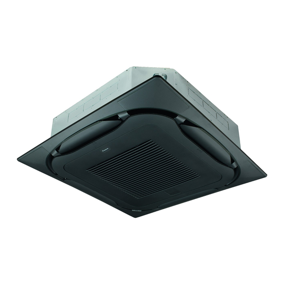
- Page 1 INSTALLATION MANUAL Decoration Panel Provided with Filter Auto Cleaning Function Self Cleaning decoration panel BYCQ140E2GW1 BYCQ140E2GFW1 BYCQ140E2GFW1B...
-
Page 2: Table Of Contents
BYCQ140E2GW1 Installation manual Self cleaning decoration panel BYCQ140E2GFW1 BYCQ140E2GFW1B CAUTION Contents • Install the indoor and outdoor units, power cord, remote controller 1. SAFETY PRECAUTIONS ............1 wiring, and transmission wiring at least 1 m away from TV or radio sets. This is for the prevention of TV and radio interference. 2. -
Page 3: Installation Site
3. Installation site Spacer Flexible S-shaped Clamp Name hose (2) pipe (3) Harness (4) This product offers selectable air outlet directions. A closure kit (an Quantity 1 pc. 1 pc. 1 pc. 1 pc. 2 pc. optional accessory) is required to achieve three-way flow patterns. Two-way flow patterns are not available to this product. -
Page 4: Preparations For Panel
4. Preparations for panel Removal of decoration corner covers Decoration corner cover Note Decoration • Perform all the required work in "4. Preparations for panel" on Decoration corner cover corner cover page 3 with the panel kept in the packing material (on the bottom side). -
Page 5: Preparations For Indoor Unit
Attaching spacer (accessory (1)) (1) Turn the two fixing knobs of the dust box. Fixing knob Dust box (1) Remove the bypass hole closing cap. Fixing knob (The front side of the panel is shown for ease of explanation.) (2) Remove the dust box from the panel while paying attention not to cut the fall prevention cord. -
Page 6: Attaching Panel To Indoor Unit
Attaching panel (2) Remove jumper connector from X70A. (1) Tentatively put the two temporary latching brackets of the suction port of the panel (on the internal circumference side) to the hooks of the indoor unit. Note Remove your hands after confirming through the check X70A window that the temporary latching brackets are engaged with the hooks. - Page 7 (2) Draw the harness and lead wires (on the panel side). Lower part of hook of 6-2 (6) the indoor unit Panel Panel Indoor unit (The ceiling is omitted from the Lead wire illustration for ease (on the panel side) Harness of explanation) Lower side...
- Page 8 (6) Guide the lead wires through the hook. (1) Hook the fall prevention cord for the dust box to the panel clasp as shown in the illustration. Hook Guide the wires through the hook Fixing gaps between the decoration panel Clasp and the ceiling Hooked fall prevention cord...
-
Page 9: Attaching Suction Grille And Decoration Corner Covers
7. Attaching suction grille and (3) Connect the flexible hose (accessory (2)) onto the panel side. (The flexible hose (accessory (2)) has no directionality constraint.) decoration corner covers Flexible hose junction The suction grill can be rotated and attached in two directions, on the panel side either one of which is selectable. - Page 10 (6) Push up the suction grille slowly first, and while pressing the (3) Connect the flexible hose (accessory (2)) onto the panel side. two knobs, finally fit the grille into the panel securely. (The flexible hose (accessory (2)) has no directionality constraint.) Panel Knobs...
-
Page 11: Operation Mode Settings
(4) Attach the decoration corner covers (i.e., the three covers) to Note the panel. The suction grille can catch the fall prevention cords while the suction grill is closed. Check that the fall prevention cords do not protrude from the suction grille before closing the suction grille. -
Page 12: Test Operation
Setting table Make field settings according to the installation manual of the Cool Set to remote controller. (Settings in bold cells are factory set default.) Press and hold Cool °C Cancel button for Second code No. 4 seconds or Setting Mode First longer during... - Page 16 4P558847-1B 2019.02...
Need help?
Do you have a question about the BYCQ140EGFB and is the answer not in the manual?
Questions and answers