Table of Contents
Advertisement
Quick Links
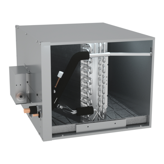
CHPE
SERIES CASED HORIZONTAL COIL
INSTALLATION INSTRUCTIONS
Index
1 Important Safety Instructions ............................................................... 2
2 Shipping Inspection .............................................................................. 3
2.1 Parts ........................................................................................................... 3
2.2 Handling ..................................................................................................... 3
3 Codes & Regulations ............................................................................ 3
4 Replacement Parts ............................................................................... 3
5 Pre-Installation Considerations ............................................................ 3
5.1 Preparation ................................................................................................ 3
5.2 System Matches ......................................................................................... 3
5.3 Clearances .................................................................................................. 4
6 Application Information ....................................................................... 4
6.1 Duct Flange Attachment ............................................................................ 4
7 Return Ductwork .................................................................................. 5
8 Refrigerant Piping Work ....................................................................... 5
8.1 Tubing Size/Length ..................................................................................... 5
8.2 Cut Off the Spin Closure ............................................................................. 6
8.3 Disconnect Internal Control Wiring ........................................................... 6
8.4 Connect Piping ........................................................................................... 6
8.5 Re-assemble the Coil and Controls ............................................................ 7
9
Sealing Along The Panel Gap ..............................................................
10 Drain Piping Work .............................................................................. 8
11 Electrical Wiring Work ....................................................................... 9
11.1 General Instructions ................................................................................. 9
11.2 Wiring Sizing ............................................................................................ 9
11.3 Safety Device .......................................................................................... 10
11.4 Transformer Installation ........................................................................ 10
11.5 How To Install The Transformer ............................................................. 10
11.5.1C No Bracket Installation ..................................................................... 12
11.6 Wiring Transformer and PCB ................................................................. 13
12 ComfortNet™ System Trademark ....................................................... 13
12.1 Overview ................................................................................................ 13
12.2 Thermostat Wiring ................................................................................. 13
12.3 Two-Wire Outdoor and Four-Wire Indoor Wiring .................................. 14
13 Miscellaneous Start-Up Checklist ....................................................... 14
14 Troubleshooting ................................................................................ 14
14.1 Electrostatic Discharge (ESD) Precautions ............................................. 14
14.2 Diagnostic Chart .................................................................................... 14
14.3 Fault Recall ............................................................................................. 15
14.4 Network Troubleshooting ...................................................................... 15
14.5 System Troubleshooting ......................................................................... 15
Communications Troubleshooting Chart ................................................... 16
Troubleshooting ....................................................................................... 17
7-Segment LED Codes ............................................................................... 17
Setting the Mode Display ......................................................................... 18
Wiring Diagram ........................................................................................ 20
Homeowner's Rountine Maintenance ....................................................... 21
ATTENTION INSTALLING PERSONNEL:
Prior to installation, thoroughly familiarize yourself with this
Installation Manual. Observe all safety warnings. During in-
stallation or repair, caution is to be observed. It is your re-
sponsibility to install the product safely and to educate the
customer on its safe use.
IO-454A
12/2018
8
Our continuing commitment to quality products may mean a change in specifications without notice.
© 2018
5151 San Felipe St., Suite 500 • Houston, TX 77056
www.daikincomfort.com
INSTALLATION INSTRUCTIONS
Only personnel that have been trained to install, adjust, service
or repair (hereinafter, "service") the equipment specified in
this manual should service the equipment. The manufacturer
will not be responsible for any injury or property damage
arising from improper service or service procedures. If you
service this unit, you assume responsibility for any injury or
property damage which may result. In addition, in jurisdictions
that require one or more licenses to service the equipment
specified in this manual, only licensed personnel should service
the equipment. Improper installation, adjustment, servicing
or repair of the equipment specified in this manual, or
attempting to install, adjust, service or repair the equipment
specified in this manual without proper training may result in
product damage, property damage, personal injury or death.
PROP 65 WARNING
FOR CALIFORNIA CONSUMERS
Cancer and Reproductive Harm -
www.P65Warnings.ca.gov
RECOGNIZE THIS SYMBOL AS A SAFETY PRECAUTION.
0140M00513-A
Advertisement
Table of Contents
Troubleshooting

Subscribe to Our Youtube Channel
Related Manuals for Daikin CHPE Series


Summary of Contents for Daikin CHPE Series
-
Page 1: Table Of Contents
INSTALLATION INSTRUCTIONS CHPE SERIES CASED HORIZONTAL COIL INSTALLATION INSTRUCTIONS Index 1 Important Safety Instructions ............... 2 2 Shipping Inspection ................3 2.1 Parts ......................3 2.2 Handling ..................... 3 3 Codes & Regulations ................3 4 Replacement Parts ................3 5 Pre-Installation Considerations ............ -
Page 2: Important Safety Instructions
1 IMPORTANT SAFETY INSTRUCTIONS The following symbols and labels are used throughout this manual to indicate immediate or potential safety hazards. It is the owner’s When installing or servicing this equipment, safety clothing, and installer’s responsibility to read and comply with all safety including hand and eye protection, is strongly recommended. -
Page 3: Shipping Inspection
Report any missing components im- equipment installed in violation of any codes or regulations. mediately to Daikin or to the distributor. Use only factory authorized replacement parts (see Section 4). Make sure The United States Environmental Protection Agency (EPA) has... -
Page 4: Clearances
5.3 Clearances Refrigerant lines must be routed, depending on configuration of unit, to maintain the required 24” minimum clearance for service. Consult all appropriate regulatory codes prior to de- termining final clearances. In installations that may lead to physical damage (i.e. a garage) it is advised to install a protec- tive barrier to prevent such damage. -
Page 5: Return Ductwork
FURNACE (Z-BRACKET WITH NARROW FURNACE) Z BRACKET (ACCESSO RY) COIL PLENUM L BRACKET (ACCESSO RY) Figure 5C FLANGE SIDE PLENUM COIL BOTTOM DUCT FLANGE Figure 4 DUCT BOARD SHEET 4. Using the hardware and brackets provided, attach the coil to M ETAL OR OTHER FILLER MATERIAL the furnace then attach the plenum to the coil (Figure 5A-5C) -
Page 6: Cut Off The Spin Closure
8.2 Cut Off The Spin Closure • This coil is shipped containing gas under 150 P.S.I.G. Re- lease pressure from the gas piping pressure-release device before initiating piping work. After the work is finished, Sharp object Reinstall cap. INTERNAL WIRING CONNECTOR (EEV, PRESSURE SENSOR, AND (1) Remove THERMISTER) -
Page 7: Re-Assemble The Coil And Controls
• Re-install the control panel to the top and bottom front panel using mounting location holes and factory supplied screws. A quenching cloth is strongly recommended to prevent scorching or marring of the equipment finish when brazing close to the •... -
Page 8: Sealing Along The Panel Gap
9 SEALING ALONG THE PANEL GAP IMPORTANT NOTE: To prevent cabinet “sweating”, apply field provided insulation tape along all joining surfaces between the coil, gas furnace, duct work, and panels. See Figure11. APPLY INSULLATION TAPE Figure 12 NOTE: • Water coming from secondary line means the coil primary Figure 11 drain is plugged and needs immediate attention. -
Page 9: Electrical Wiring Work
• Shut off the power before doing any work. charge out of the open Tee. Daikin does not prohibit this type of drain but we also do not recommend it due to the resulting air •... -
Page 10: Safety Device
11.3 SAFETY DEVICE Every installation must include an NEC (USA) or CEC (Canada) ap- proved overcurrent protection device. Also, check with local or This unit is designed to operate on 24 VAC from provided state codes for any special regional requirements. Protection can transformer. -
Page 11: Installation Bracket - "A
11.5.1A INSTALLATION BRACKET - “A” FOR 17.5” WIDTH CABINET FURNACE: A furnace transformer should be removed from the PCB control deck. Align transformer bracket “A” and furnace transformer to the mounting holes of the furnace transformer on the PCB control deck. Bracket “A” should be located between the PCB control deck and furnace transformer (see Figure 17). -
Page 12: No Bracket Installation
FOR 96 / 97% DOWNFLOW FURNACE (17.5” width cabinet) Fasten the PCB transformer using (1) field supplied screw at the extra screw hole on the PCB mounting plate. Then secure an- other screw hole of PCB transformer using (1) field supplied, self- drilling screw. -
Page 13: Wiring Transformer And Pcb
NOTE: You should use a DAIKIN approved thermostat (CTK04AE or modular blower cabinet and onto electrical components. newer). Not approved for use with a CTK01, CTK02, CTK03, CTK04AD or older. -
Page 14: Two-Wire Outdoor And Four-Wire Indoor Wiring
12.3 Two-Wire Outdoor and Four-Wire Indoor Wiring TROUBLESHOOTING Typical wiring will consist of two wires between the indoor unit 14.1 Electrostatic Discharge (ESD) Precautions and outdoor unit and four wires between the indoor unit and NOTE: Discharge your body’s static electricity before touching thermostat. -
Page 15: Fault Recall
14.3 Fault Recall 14.4 Network Troubleshooting The integrated control module is equipped with a momentary The ComfortNet system is a fully communicating system, consti- push-button switch that can be used to display the last six faults tuting a network. Occasionally the need to troubleshoot the on the 7 segment LED display. -
Page 16: Communications Troubleshooting Chart
COMMUNICATIONS TROUBLESHOOTING CHART In d icatio n P o ssib le Cau ses Co rrect iv e A ctio n (s) N o tes & Cau tio n s S t at u s N o n e N o n e ... -
Page 17: Troubleshooting
TROUBLESHOOTING Error ClimateTalk Message Description Possible Causes Corrective Actions Code LED Display • Manual disconnect switch OFF • Assure 24 volt power to blower and control board. No display • No 24 volt power to PCB • No 24 volt power to PCB •... -
Page 18: Setting The Mode Display
SETTING THE MODE DISPLAY MODE DISPLAY INTRODUCTION A 2-digit display is provided on the printed circuit board (PCB) as a backup tool to the thermostat for accessing error codes and erasing error code history of the indoor unit. Follow the information provided in this section to learn how to use the mode display DISPLAY The display consists of 2 digits. - Page 19 SETTING THE MODE DISPLAY <SCREEN ZERO> First Error Code Idle Release Fault Recall in less than 2 sec mins. Press Fault Recall for Error Code Second Error Code Hold Fault Recall for more than 2 sec Solid Display Press Fault Recall for Error Code Release Fault Last Error Code...
-
Page 20: Wiring Diagram
WIRING DIAGRAM NOTE: THESE INSTRUCTIONS ARE SPECIFICALLY FOR CHPE MODELS. HIGH VOLTAGE! DISCONNECT ALL POWER BEFORE DO NOT ATTEMPT TO APPLY THESE DIAGRAMS TO ANY OTHER SERVICING. MULTIPLE POWER SOURCES MAY BE MODELS. PRESENT. FAILURE TO DO SO MAY CAUSE PROPERTY DAMAGE, PERSONAL INJURY OR DEATH. -
Page 21: Homeowner's Rountine Maintenance
CASED COIL CASED COIL HOMEOWNER’S ROUTINE MAINTENANCE RECOMMENDATIONS We strongly recommend a bi-annual maintenance checkup be performed before the heating and cooling seasons begin by a qualified servicer. REPLACE OR CLEAN FILTER IMPORTANT NOTE: Never operate unit without a filter installed as dust and lint will build up on internal parts resulting in loss of efficiency, equipment damage and possible fire. - Page 22 THIS PAGE INTENTIONALLY LEFT BLANK...
- Page 23 THIS PAGE INTENTIONALLY LEFT BLANK...
- Page 24 CUSTOMER FEEDBACK Daikin is very interested in all product comments. Please fill out the feedback form on the following link: https://daikincomfort.com/contact-us You can also scan the QR code on the right to be directed to the feedback page. PRODUCT REGISTRATION Thank you for your recent purchase.
Need help?
Do you have a question about the CHPE Series and is the answer not in the manual?
Questions and answers