Table of Contents
Advertisement
Advertisement
Chapters
Table of Contents
Troubleshooting

Subscribe to Our Youtube Channel
Related Manuals for Daikin EDBE81-327


Summary of Contents for Daikin EDBE81-327
- Page 1 EDBE81 - 327 Engineering Data Air Purifiers Photocatalytic Air Purifiers...
-
Page 2: Table Of Contents
EDBE81-327 Air Purifiers MC704VM 1. Introduction 1.1 Features ....................2 1.2 Performance ..................3 1.3 Functions ....................5 2. Precautions for Use 2.1 Use Conditions ..................7 2.2 Applicable Room Area ................7 3. Specifications 3.1 Specification List ...................8 3.2 Dimension .....................9 3.3 Wiring Diagram ..................9 3.4 Packaging Drawing ................10... -
Page 3: Introduction
Top class ! Top class ! Top class ! Quiet Operation Flat panel Negative ions MC704VM Childproof Function Daikin Filter System Daikin Filter System Daikin Filter System Daikin Filter System Long-lasting 7-year Filter roll Three-stage photocatalytic Plasma dust decomposition and deodorization... -
Page 4: Performance
EDBE81-327 Introduction Main Specifications Main Specifications Main Specifications Main Specifications MC401VE MC704VM (Current Model) Dimensions 498x400x198 500x425x225 (HxWxD)(mm) Applicable area (m ) 41.0 33.4 HH / H / M / L / LL HH / H / M / L / LL... - Page 5 Introduction EDBE81-327 Photocatalysis Photocatalysis Photocatalysis Photocatalysis When light strikes Photocatalytic technology is titanium oxide, also used in lots of other places. hydrogen peroxide (H O ) and hydroxyl 2 2 2 2 2 2 2 2 radicals (OH) are formed.
-
Page 6: Functions
EDBE81-327 Introduction Functions High High High High- - - - power Turbo Mode power Turbo Mode power Turbo Mode power Turbo Mode Powerful dust-collecting performance & deodorizing with large air flow. High-power turbo mode High-power turbo mode is for quick air purifying and deodorizing when you need it, for instance after smoking. - Page 7 Introduction EDBE81-327 A Variety of Convenient Functions A Variety of Convenient Functions A Variety of Convenient Functions A Variety of Convenient Functions Childproof function Remote controller Easy to carry holder Have you ever Even if a curious child With one hand free...
-
Page 8: Precautions For Use
EDBE81-327 Precautions for Use 2. Precautions for Use Use Conditions Ambient Temperature/Humidity Use this product under the following conditions. Operating conditions ° ° Room temperature C - 32 Room humidity 80% or less Use under other conditions may cause malfunction. -
Page 9: Specifications
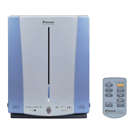
Specifications EDBE81-327 3. Specifications Specification List Model MC704VM Regulation Type Photocatalytic air purifier Style Desktop/wall-hung Color Sparkling silver and metallic ocean blue φ Power supply 220 – 240/220 – 230V, 50/60Hz Electric Running current 0.46 characteristics Rated power consumption Type... -
Page 10: Dimension
EDBE81-327 Specifications Dimension MC704VM • Required installation space Air outlet grille Signal Transmitter 500. or more 500. or more Air inllet grille • Dimension of remote controller ( ARC437A2 ) Handles PHOTOCATALYTIC AIR PURIFIER Air inllet grille Manufacturer's Label Power supply cord Approx. -
Page 11: Packaging Drawing
Specifications EDBE81-327 Packaging Drawing Photocatalyst filter roll Wireless remote controller Product cover (attached to the back side) 3P098535F Photocatalytic Air Purifiers... -
Page 12: Operation Manual 4.1 General Description
EDBE81-327 Operation Manual 4. Operation Manual General Description Contents Tips for Appropriate General Description..........1 Accessory.............. 1 • When you want to remove house dust, setting up the air purifier in low rooms is effective. When you want to remove cigarette smoke, Tips for Appropriate Use ........ -
Page 13: Safety Precautions
Operation Manual EDBE81-327 Safety Precautions Safety Precautions • Keep this manual where the operator can easily find them. • Do not use outdoors or where exposed to direct • Read this manual attentively before starting up the unit. sunlight. • For the reason of safety the operator must read the following cau- Direct sunlight can weaken remote controller signal reception tions carefully. -
Page 14: Names And Operation Of Each Part
EDBE81-327 Operation Manual Names and Operation of each Part Names and Operation of each Part Main unit Front Rear 1 Front panel CAUTION 2 Main unit display (Page 4) • Do not strongly press on the photocatalyst. Shows operation status. -
Page 15: Main Unit Display
Operation Manual EDBE81-327 Main unit display 1 Air intake for dust sensor 9 Child lock lamp (Page 7) Air is taken in from here and the dust sensor detects the dirty state Lit during child lock. of the air. 10 Negative ion mode indicator... -
Page 16: Preparation Before Operation
For these cases, discuss with the Daikin dealer. • If other electrical device operate by the remote controller, either sep- arate them from the remote controller or discuss with the Daikin dealer. 2 Remote controller storage Set the filter roll •... -
Page 17: Operation Manual
Operation Manual EDBE81-327 3. Install the filter roll. 4. Install the plasma ionizer in its original configuration. (1) Cut off one piece along the perforation. Filter roll Hole Hole (2) Place the dark colored surface facing up and then correctly insert into the hooks (four) of the plasma ionizer. -
Page 18: How To Operate
EDBE81-327 Operation Manual How to Operate How to Operate 7 When you want to decide a time to stop operation Press the “ ” [OFF TIMER] button. • Each time it is pressed the timer setting switches as shown below. -
Page 19: Care And Cleaning
Operation Manual EDBE81-327 Care and Cleaning Care and Cleaning 3. Clean the pre-filter. WARNING • After using a vacuum cleaner to remove any dust, clean with water. During maintenance you must stop the oper- • If it is very dirty, use a soft brush or a neutral cleaner to clean then ation and remove the power plug from the dry well in the shade. - Page 20 EDBE81-327 Operation Manual Care and Cleaning Replacing the filter roll CAUTION Replace the filter roll when the “Replace indicator” (Page 4) is lit or flashes in the main unit display. If the front surface and rear surface of the filer are mis- Target is once every year.
- Page 21 • Be careful not to snag or cut the ionizing line. If the ionizing line is pole plates. (Wearing rubber gloves is safer.) cut, request the Daikin dealer to replace it. If the unit is operated with the ionizing line cut, there will be no dust collection.
-
Page 22: Sensitivity Settings Of The Dust Sensor
For example, if installed at a low position in the room, the response for cigarette smoke will worsen. Order the replacement filter roll at a Daikin dealer. For this case, try installing the unit at a high position such as on a rack. If... -
Page 23: Trouble Shooting
The four airflow rate displays, LL (Quiet), Is there any foreign matter in the air outlet? Remove the foreign matter. For other cases, contact a Daikin dealer. L (Low), M (Standard) and H (High) are flashing at the same time. -
Page 24: Optional Accessories
EDBE81-327 Optional Accessories 5. Optional Accessories Specifications/Dimension Filter Roll BAC14D SPECIFICATIONS : NONWOVEN FABRIC ( ELECTROSTATIC PROPERTY ) FILTER ELEMENT : ABOUT 7 YEARS ( 1SHEET/YEAR×7SHEETS ) TARGET OF REPLACEMENT THICKNESS OF FILTER ELEMENT : 1.6mm ( 2400 ) ( OVERALL FILTER LENGTH ) 330 ×... -
Page 25: Basic Inspection
Troubleshooting EDBE81-327 6. Troubleshooting Basic Inspection (1) Is the connector for the PCB plugged in? Or is there any poor connection? (2) Is the wire harness broken? Troubleshooting with Airflow Rate Indicator The airflow rate indicators flicker only when the DC fan is locked. -
Page 26: Troubleshooting (Case-By-Case)
EDBE81-327 Troubleshooting Troubleshooting (case-by-case) 1. Equipment does not Operate, or Operation Lamps does not Light *Be sure to insert/pull out the connector after Models Covered Troubleshooting turning off the power. It may cause malfunction. Diagnosis Remedy MC704VM *Release child lock. - Page 27 Troubleshooting EDBE81-327 2. Remote controller Sends Signals Erratically *Be sure to insert/pull out the connector after Models Covered Troubleshooting turning off the power. It may cause malfunction. Diagnosis Remedy MC704VM *Release child lock. Replace battery. Is battery correct? (2.5V or more?)
- Page 28 EDBE81-327 Troubleshooting 3. Sensor LED Remains Lit *Be sure to insert/pull out the connector after Models Covered Troubleshooting turning off the power. It may cause malfunction. Diagnosis Remedy MC704VM <Dust sensor unit LED> Remove dust sensor unit. Keep holding down door switch and press ON/OFF switch.
- Page 29 Troubleshooting EDBE81-327 4. PCB is Defective *Be sure to insert/pull out the connector after Models Covered Troubleshooting turning off the power. It may cause malfunction. Diagnosis Remedy MC704VM Remove panel. Is there 12V DC between Method of Mal- Replace display JP14 and GND while holding PCB.
- Page 30 EDBE81-327 Troubleshooting 5. DC Fan Lock *Be sure to insert/pull out the connector after Models Covered Troubleshooting turning off the power. It may cause malfunction. Diagnosis Remedy MC704VM Four airflow rate indicator flicker simultaneously. Retry to operate with NOTE: If connector ON/OFF switch.
- Page 31 Troubleshooting EDBE81-327 6. LED Automatically Operates *Be sure to insert/pull out the connector after Models Covered Troubleshooting turning off the power. It may cause malfunction. Diagnosis Remedy MC704VM *Entering demo LED may be in demo mode. mode Keep holding down reset switch and Exit demo mode.
- Page 32 EDBE81-327 Troubleshooting 7. Negative Ions are not Generated *Be sure to insert/pull out the connector after Models Covered Troubleshooting turning off the power. It may cause malfunction. Diagnosis Remedy MC704VM The negative ion Is the unit new? Is connector off? generator may be dirty.
-
Page 33: Removal Procedure
Removal Procedure EDBE81-327 7. Removal Procedure WARNING 7.1 Removal of External Accessories Make sure the unit is disconnected from any power source before disassembly. Procedure Points 1. Appearance Rear topside Operation switch/stop button 2. Removing the front panel (1) Hold the bottom... - Page 34 EDBE81-327 Removal Procedure Procedure Points * The pre-filter can be 3. Removing the removed with the plasma ionizer plasma ionizer attached. (1) Hold the handle of the plasma ionizer and pull it towards you to remove. Plasma ionizer 4. Removing the filters...
-
Page 35: Removal Of Lonizing Wire
Removal Procedure EDBE81-327 WARNING 7.2 Removal of lonizing Wire Make sure the unit is disconnected from any power source before disassembly. Procedure Points * The front panel has been removed. 1. Removing the opposing plates (1) Release the outer claws and lift the opposing plates to remove. -
Page 36: Removal Of Electrical Parts (Special Inverter Lamp)
EDBE81-327 Removal Procedure WARNING 7.3 Removal of Electrical Parts (Special Inverter Lamp) Make sure the unit is disconnected from any power source before disassembly. Procedure Points * The front panel has been removed. <Front> * The plasma ionizer has been removed. - Page 37 Removal Procedure EDBE81-327 Procedure Points (2) Remove the Inverter PCB for connector (CN2) from the special lamp the inverter PCB (A3P). 3. Removing the photocatalyst filter (1) Remove the two screws. (2) Detach the photocatalyst filter holder. Photocatalytic Air Purifiers...
- Page 38 EDBE81-327 Removal Procedure Procedure Points (3) Remove the * Handle with great care, the photocatalyst filter is photocatalyst filter. made of paper. 4. Removing the special lamp (1) Detach the special inverter lamp. Photocatalytic Air Purifiers...
-
Page 39: Removal Of Pcbs
Removal Procedure EDBE81-327 WARNING 7.4 Removal of PCBs Make sure the unit is disconnected from any power source before disassembly. Procedure Points * The back cover has been removed. 1. Removing the inverter PCB (1) Detach the connector (CN1) and remove the inverter PCB. - Page 40 EDBE81-327 Removal Procedure Procedure Points (2) Remove the connector (CN1) from the power PCB (A4P). (3) Remove the two screws and detach the power PCB. Photocatalytic Air Purifiers...
- Page 41 Removal Procedure EDBE81-327 Procedure Points (4) Detach the two terminals and pull out the power PCB to remove. 3. Removing the display cover (1) Release the three claws and remove the display cover. Photocatalytic Air Purifiers...
- Page 42 EDBE81-327 Removal Procedure Procedure Points 4. Removing the dust sensor (1) Detach the connector on the back of the dust sensor. 5. Removing the display PCB (1) Release the five claws and remove the display PCB. Photocatalytic Air Purifiers...
-
Page 43: Removal Of Fan Motor
Removal Procedure EDBE81-327 WARNING 7.5 Removal of Fan Motor Make sure the unit is disconnected from any power source before disassembly. Procedure Points * The front panel has been removed. * The back cover has been removed. * When assembling, 1. - Page 44 EDBE81-327 02/2003 B NK...
Need help?
Do you have a question about the EDBE81-327 and is the answer not in the manual?
Questions and answers