Advertisement
Quick Links
Advertisement

Related Manuals for SIGLENT SDG1062X


Summary of Contents for SIGLENT SDG1062X
- Page 1 SDG1000X Series Function/Arbitrary Waveform Generator Quick Start QS0201X-E01A...
-
Page 2: Copyright
Information in this publication replaces all previous corresponding material. SIGLENT reserves the rights to change the specifications and the price. Contents of this manual are not allowed to be copied, extracted, or translated without the permission of Siglent Technologies. I-SDG1000X Quick Start... - Page 3 General Safety Summary Carefully read the following safety precautions to avoid any personal injuries or damages to the instrument and any product connected to it. To avoid potential hazards, please use the instrument as specified. Any service on this instrument should be performed by qualified repair personnel only. Avoid exposing this instrument to fire.
-
Page 4: Table Of Contents
Content Copyright.............. General Safety Summary........Adjust the Handle..........The Front Panel............ The Rear Panel............ User Interface............Using the Built-in Help System....... Introduction to EasyWave........Contact SIGLENT..........1-SDG1000X Quick Start... -
Page 5: Adjust The Handle
Adjust the Handle When using the instrument, users can adjust the handle to a desired position for optimum use. Carrying Position Horizontal Position Figure 1 Adjust the Handle SDG1000X Quick Start-2... -
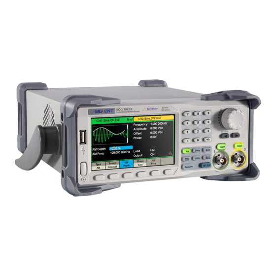
Page 6: The Front Panel
The Front Panel The figure below shows the SDG1000X’s front panel layout: 1. Power Switch 2. USB Host 3. User Interface 4. Numeric Keyboard 5. Knob 6. Arrow Keys 7. CH1/CH2 Control/ Output Port 8. Channel Select Key 9. Function Keys 10. - Page 7 1.Power Switch This switch is used to turn on/off the SDG1000X. When the power switch is off, SDG1000X is in the power off state. 2.USB Host SDG1000X supports U-Disk using FAT format. It is used to read waveforms or state files from a U-Disk or store the current state of the instrument to the U-Disk. Users can update the firmware through a U-Disk.
- Page 8 7.Channel Control Area CH1 Control/Output Key The Output key on the left is used to turn on/off CH1 output. The nominal output impedance of the BNC connector is 50 Ω. When pressing Output (the key backlight turns on), the connector outputs the waveform according to the current configuration of CH1. CH2 Control/Output Key The Output key on the right is used to turn on/off CH2 output.
- Page 9 9.Function Keys Mod ----Modulation This key is used to enable the modulation screen and allow for several types of modulation. Types include AM, DSB-AM, FM, PM, ASK, FSK, PSK and PWM modulated signals. • Both “Internal” and “External” modulation sources are supported. •...
- Page 10 Utility ----Utility Functions and System Settings This key is used to set system parameters and check version information. •Press this key and then press the help softkey to obtain built-in help information about the product. •The corresponding key backlight will turn on when this function is selected. Store/Recall ----Store and Recall Store/recall the instrument’s state or arbitrary waveform data edited by users.
- Page 11 Waveforms ---- Ramp Provides ramp waveform output which ranges from 1 μHz to 500 kHz. • “Frequency/Period”, “Amplitude/High level”, “Offset/Low level”, “Phase” and “Symmetry” of the ramp waveform can be modified. Waveforms ---- Pulse Provides pulse waveform output which ranges from 1 μHz to 12.5 MHz. •...
-
Page 12: The Rear Panel
The Rear Panel Figure 3 SDG1000X Rear Panel 9-SDG1000X Quick Start... - Page 13 1.Counter BNC connector. The input impedance is 1 MΩ. This connector is used to accept the signal measured by the frequency counter. 2.Aux In/Out BNC connector. The function of this connector is determined by the current operating mode of the instrument. •...
- Page 14 5.AC Power Supply Input SDG1000X can accept two different types of AC input power. AC power: 100-240V, 50/60Hz or 100-120V, 400Hz Fuse: 1.25A, 250V 6.USB Device Used when connecting the instrument to an external computer to allow waveform editing ( i.e., EasyWave) and remote control. 7.LAN Interface Through this interface, the generator can be connected to a computer or network for remote control.
-
Page 15: User Interface
User Interface SDG1000X can only display parameters and waveform of one channel at a time. The picture below shows the interface when CH1 is selected and AM modulation of a sine wave function is selected. The information displayed may vary depending on the function selected. Figure 4 User Interface 1.Waveform Display Area Displays the currently selected waveform of each channel. - Page 16 2.Channel Status Bar Indicates the selected status and output configuration of the channels. 3.Basic Waveform Parameters Area Shows the current waveform’s parameters of each channel. Press Parameter and select the corresponding softkey to highlight the parameter to configure. Then use number keys or knob to change the parameter value.
-
Page 17: Using The Built-In Help System
Using the Built-In Help System To obtain built-in help information, press Utility key first, then press Page 1/2 and Help . Use the knob to choose the help item you want and then press Select to obtain help information. The common help information is listed as the following: 1.System information. -
Page 18: Introduction To Easywave
Introduction to EasyWave Arbitrary editing software, EasyWave, provides 9 standard waveforms: Sine, Square, Ramp, Pulse, ExpRise, ExpFall, Sinc, Noise and DC, which meets most engineers’ basic needs. In addition, it provides several ways of manual drawing, point-to-point line drawing and arbitrary point drawing. EasyWave allows for fast and easy creation of complex waveforms. -
Page 19: Contact Siglent
Contact SIGLENT SIGLENT TECHNOLOGIES CO., LTD Address: 3/F, NO.4 building, Antongda Industrial Zone, 3rd Liuxian Road, 68th District, Baoan District, Shenzhen, P.R. China Tel: 400- 878 -0807 E-mail: sales@siglent.com http: //www.siglent.com SDG1000X Quick Start-16... - Page 20 www.siglent.com...
Need help?
Do you have a question about the SDG1062X and is the answer not in the manual?
Questions and answers