Table of Contents
Advertisement
When you installing AGP card, please make sure the following
notice is fully understood and practiced. If your AGP card has
"AGP 4X/8X(1.5V) notch"(show below), please make sure your AGP
card is AGP 4X/8X(1.5V).
AGP 4X/8X notch
Caution: AGP 2X card is not supported by SiS
648/648FX. You
®
might experience system unable to boot up normally. Please insert
an AGP 4X/8X card.
Example 1: Diamond Vipper V770 golden finger is compatible with 2X/4X
mode AGP slot. It can be switched between AGP 2X(3.3V) or 4X(1.5V)
mode by adjusting the jumper. The factory default for this card is
2X(3.3V). The GA-8SG800/GA-8S648FX (or any AGP 4X only)
motherboards might not function properly, if you install this card without
switching the jumper to 4X(1.5) mode in it.
Example 2: Some ATi Rage 128 Pro graphics cards made by "Power
Color", the graphics card manufacturer & some SiS 305 cards, their
golden finger is compatible with 2X(3.3V)/4X(1.5V) mode AGP slot, but
they support 2X(3.3V) only. The GA-8SG800/GA-8S648FX
(or any AGP 4X only) motherboards might not function properly, If you
install this card in it.
Note : Although Gigabyte's AG32S(G) graphics card is based on
ATi Rage 128 Pro chip, the design of AG32S(G) is compliance
with AGP 4X(1.5V) specification. Therefore, AG32S (G)will work
fine with SiS
648/648FX based motherboards.
®
Advertisement
Table of Contents

Related Manuals for Gigabyte GA-8S648FX


Summary of Contents for Gigabyte GA-8S648FX
- Page 1 (or any AGP 4X only) motherboards might not function properly, If you install this card in it. Note : Although Gigabyte's AG32S(G) graphics card is based on ATi Rage 128 Pro chip, the design of AG32S(G) is compliance with AGP 4X(1.5V) specification. Therefore, AG32S (G)will work fine with SiS 648/648FX based motherboards.
- Page 2 M The author assumes no responsibility for any errors or omissions that may appear in this document nor does the author make a commitment to update the information contained herein. M Third-party brands and names are the property of their respective owners. M Please do not remove any labels on motherboard, this may void the warranty of this motherboard.
-
Page 3: Declaration Of Conformity
Declaration of Conformity We, Manufacturer/Importer (full address) G.B.T. Technology Träding GMbH declare that the product Mother Board GA-8SG800/GA-8S648FX is in conformity with in accordance with 89/336 EEC-EMC Directive o EN 61000-3-2* T EN 60555-2 o EN 61000-3-3* T EN 60555-3... - Page 4 (2) this device must accept any inference received, including that may cause undesired operation. Representative Person’s Name: G.B.T. INC. (U.S.A.) Address: 17358 Railroad Street City of Industry, CA 91748 (818) 854-9338/ (818) 854-9339 Motherboard GA-8SG800/GA-8S648FX ERIC LU Signature: Eric Lu Date: May 2, 2003...
- Page 5 GA-8SG800/GA-8S648FX P4 Titan Series Motherboard USER'S MANUAL Pentium 4 Processor Motherboard ® Rev. 1103 12ME-8SG800-1103...
-
Page 6: Table Of Contents
WARNING! ... 4 Chapter 1 Introduction ... 5 Features Summary ... 5 GA-8SG800/GA-8S648FX Motherboard Layout ... 7 Chapter 2 Hardware Installation Process ... 8 Step 1: Install the Central Processing Unit (CPU) ... 9 Step 1-1: CPU Installation ... 9 Step 1-2: CPU Cooling Fan Installation ... - Page 7 PnP/PCI Configurations ... 37 PC Health Status ... 38 Frequency/Voltage Control ... 40 Top Performance ... 42 Load Fail-Safe Defaults ... 43 Load Optimized Defaults ... 44 Set Supervisor/User Password... 45 Save & Exit Setup ... 46 Exit Without Saving ... 47 Chapter 4 Technical Reference ...
-
Page 8: Item Checklist
þ Quick PC Installation Guide o RAID Manual WARNING! Computer motherboards and expansion cards contain very delicate Integrated Circuit (IC) chips. To protect them against damage from static electricity, you should follow some precautions whenever you work on your computer. -
Page 9: Chapter 1 Introduction
— 1 Parallel port supports Normal/EPP/ECP mode — 2 Serial ports (COMA&COMB) — 6 USB 2.0/1.1 ports (2 x Rear, 4 xFront by cable) — 1 Front Audio Connector "*" For GA-8S648FX only "**" For GA-8SG800 only Micro FC-PGA2 Pentium ®... - Page 10 CPU, chipset and most of the peripherals. Whether your system can run under these specific bus frequencies properly will depend on your hardware configurations, including CPU, Chipsets,SDRAM,Cards… .etc. GA-8SG800/GA-8S648FX Motherboard - 6 -...
-
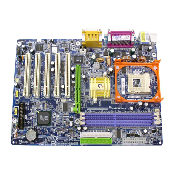
Page 11: Ga-8Sg800/Ga-8S648Fx Motherboard Layout
GA-8SG800/GA-8S648FX Motherboard Layout KB_MS A TX_12V F_AU DIO AUX_IN CODEC BIOS P4 Titan SPDIF "*" For GA-8S648FX only "**" For GA-8SG800 only SOC KET478 NB_FAN SiS 648**/SiS 648FX* PCI1 1 39 4 PCI2 PCI3 PCI4 PCI5 F_U SB2 SYS _FAN... -
Page 12: Chapter 2 Hardware Installation Process
Step 3- Install expansion cards Step 4- Connect ribbon cables, cabinet wires, and power supply Step 5- Setup BIOS software Step 6- Install supporting software tools Step 4 Step 3 GA-8SG800/GA-8S648FX Motherboard Step 4 Step 1 Step 2 - 8 - Step 4... -
Page 13: Step 1: Install The Central Processing Unit (Cpu)
Step 1: Install the Central Processing Unit (CPU) Step 1-1: CPU Installation Angling the rod to 65 1. Angling the rod to 65-degree maybe feel a kind of tight, and then continue pull the rod to 90-degree when a noise "cough" made. -
Page 14: Step 1-2: Cpu Cooling Fan Installation
M Make sure the CPU fan power cable is plugged in to the CPU fan connector, this completes the installation. M Please refer to CPU cooling fan user's manual for more detail installation procedure. GA-8SG800/GA-8S648FX Motherboard 2. Hook the other end of the cooler bracket to the CPU socket. -
Page 15: Step 2: Install Memory Modules
The DIMM module can only fit in one direction due to the notch. Memory size can vary between sockets. Support Unbuffered DDR DIMM Sizes type: 64 Mbit (2Mx8x4 banks) 128 Mbit(2Mx16x4 banks) 512 Mbit(16Mx8x4 banks) This table contains the specification update of GA-8S648FX CPU type and DRAM type. CPU Type DRAM Type FSB 800MHz DDR400 DDR333... -
Page 16: Step 3: Install Expansion Cards
7. Power on the computer, if necessary, setup BIOS utility of expansion card from BIOS. 8. Install related driver from the operating system. AGP Card GA-8SG800/GA-8S648FX Motherboard Please carefully pull out the small white- drawable bar at the end of the AGP slot when you try to install/ Uninstall the AGP card. -
Page 17: Step 4: Connect Ribbon Cables, Cabinet Wires, And Power Supply
Step 4: Connect ribbon cables, cabinet wires, and power supply Step 4-1: I/O Back Panel Introduction u PS/2 Keyboard and PS/2 Mouse Connector PS/2 Mouse Connector (6 pin Female) PS/2 Keyboard Connector (6 pin Female) v USB Connector USB 0 USB 1 ØThis connector supports standard PS/2 keyboard and PS/2 mouse. -
Page 18: Audio Connectors
(Rear Speaker) If you want the detail information for 2-/4-/6-channel audio setup installation, please refer to page 67. GA-8SG800/GA-8S648FX Motherboard ØThis connector supports 2 standard COM ports and 1 Parallel port. Device like printer can be connected to Parallel port ; mouse and modem etc can be connected to Serial ports. -
Page 19: Step 4-2: Connectors Introduction
Step 4-2: Connectors Introduction 1) CPU_FAN 2) SYS_FAN 3) NB_FAN 4) ATX_12V 5) ATX 6) IDE1/IDE2 7) FDD 8) PWR_LED 9) F_PANEL 10) BAT 11) F_AUDIO 12) SUR_CEN 13) CD_IN 14) AUX_IN 15) SPDIF 16) F_USB1/F_USB2 17) 1394 18) CI - 15 - Hardware Installation Process... - Page 20 3) NB_FAN (Chip FAN Connector) +12V 4) ATX_12V (+12V Power Connector) +12V +12V GA-8SG800/GA-8S648FX Motherboard Ø Please note, a proper installation of the CPU cooler is essential to prevent the CPU from running under abnormal condition or damaged by overheating.The CPU fan connector supports Max.
- Page 21 5) ATX (ATX Power) +12V 5V SB (Stand by +5V) Power Good 3.3V 3.3V 6) IDE1/ IDE2 [IDE1 / IDE2 Connector(Primary/Secondary)] IDE1 IDE2 7) FDD (Floppy Connector) Ø AC power cord should only be connected to your power supply unit after ATX power cable and other related devices are firmly connected to the mainboard.
- Page 22 Ø Please connect the power LED, PC speaker, reset switch and power switch etc of your chassis front panel to the F_PANEL connector according to the pin assignment above. GA-8SG800/GA-8S648FX Motherboard Ø PWR_LED is connect with the system power indicator to indicate whether the system is on/off.
- Page 23 10) BAT (Battery) 11) F_AUDIO (Front Audio Connector) Rear Audio (L) Front Audio (L) Reserved Rear Audio (R) Front Audio (R) POWER 12) SUR_CEN BASS_OUT CENTER_OUT SUR OUTL SUR OUTR 13) CD_IN (CD Audio Line In) CD-L CD-R CAUTION v Danger of explosion if battery is incorrectly replaced.
- Page 24 LINKON +12V +12V LREQ CTL0 GA-8SG800/GA-8S648FX Motherboard Ø Connect other device(such as PCI TV Tunner audio out )to the connector. Ø The SPDIF output is capable of providing digital audio to external speakers or com pressed AC3 data to an external Dolby Digital Decoder.
- Page 25 18) CI (CASE OPEN) Signal Ø This 2 pin connector allows your system to enable or disable the “ Case Open” item in BIOS if the system case begin remove. - 21 - Hardware Installation Process...
- Page 26 GA-8SG800/GA-8S648FX Motherboard - 22 -...
-
Page 27: Chapter 3 Bios Setup
Chapter 3 BIOS Setup BIOS Setup is an overview of the BIOS Setup Program. The program that allows users to modify the basic system configuration. This type of information is stored in battery-backed CMOS RAM so that it retains the Setup information when the power is turned off. ENTERING SETUP Powering ON the comput e r and pressing <Del>... -
Page 28: The Main Menu (For Example: Bios Ver. : F2)
Standard CMOS Features This setup page includes all the items in standard compatible BIOS. Advanced BIOS Features This setup page includes all the items of Award special enhanced features. GA-8SG800/GA-8S648FX Motherboard Top Performance Load Fail-Safe Defaults Load Optimized Defaults Set Superv isor Passw ord Set User Passw ord Sav e &... -
Page 29: Integrated Peripherals
Integrated Peripherals This setup page includes all onboard peripherals. Power Manag ement Setup This setup page includes all the items of Green function features. PnP/PCI Configurations This setup page includes all the configurations of PCI & PnP ISA resources. PC Health Status This setup page is the System auto detect Temperature, voltage, fan, speed. -
Page 30: Standard Cmos Features
The month, Jan. Through Dec. 8Month The day , from 1 to 31 (or the max imum allow ed in the month) 8Day The y ear, from 1999 through 2098 8Year GA-8SG800/GA-8S648FX Motherboard Standard CMOS Features Fri, May 3 2002 17:56:23 None None... - Page 31 C Time The times format in <hour> <mi n ute> <second>. The time is calculated base on the 24-hour military- time clock. For example, 1 p.m. is 13:00:00. C IDE Pri mary Master, S lave / IDE Secondary Master, Slave The category identifies the types of hard disk from drive C to F that has been installed in the computer.
-
Page 32: Base Memory
Extended Memory The BIOS determines how much extended memory is present during the POST. This is the amount of memory located above 1 MB in the CPU’ s memory address map. GA-8SG800/GA-8S648FX Motherboard - 28 -... -
Page 33: Advanced Bios Features
Advanced BIOS Features CMOS Setup Utility -Copy right (C) 1984-2002 Aw ard Softw are First Boot Dev ice Second Boot Dev ice Third Boot Dev ice Boot Up Floppy Seek Passw ord Check # CPU Hy per-Threading Flex ible AGP 8X Init Display First higf: Mov e Enter:Select +/-/PU/PD:Value F5:Prev ious Values... -
Page 34: Password Check
Set AGP transfer rate to 4X mode no matter w hat the AGP transfer rate t h e card is. CInit Display First Set Init Display First to AGP. (Default v alue) 8AGP Set Init Display First to PCI. 8PCI GA-8SG800/GA-8S648FX Motherboard - 30 -... -
Page 35: Integrated Peripherals
Integrated Peripherals CMOS Setup Utility -Copy right (C) 1984-2002 Aw ard Softw are IDE1 Conductor Cable IDE2 Conductor Cable On-Chip Primary PCI IDE On-Chip Secondary PCI IDE AC97 Audio USB Controller USB Legacy Support Onboard Serial Port 1 Onboard Serial Port 2 Onboard Parallel Port Parallel Port Mode x ECP Mode Use DMA... -
Page 36: Ac97 Audio
8Disabled C USB Legacy Support When USB keyboard or mouse is installed, please set at Enabled. Enabled USB key board or mouse support. 8Enabled Disabled USB key board or mouse support. (Default v alue) 8Disabled GA-8SG800/GA-8S648FX Motherboard - 32 -... -
Page 37: Onboard Serial Port
C Onboard Serial Port 1 BIOS w ill automatically setup the port 1 address. 8Auto Enable onboard Serial port 1 and address is 3F8. (Default v alue) 83F8/IRQ4 Enable onboard Serial port 1 and address is 2F8. 82F8/IRQ3 Enable onboard Serial port 1 and address is 3E8. 83E8/IRQ4 Enable onboard Serial port 1 and address is 2E8. - Page 38 Set Midi Port Address to 300. 8300 Set Midi Port Address to 330.(Default Value) 8330 Disable this function. 8Disabled CMidi Port IRQ Set Midi Port IRQ to 5. Set Midi Port IRQ to 10. (Default Value) GA-8SG800/GA-8S648FX Motherboard - 34 -...
-
Page 39: Power Management Setup
Power Management Setup CMOS Setup Utility -Copy right (C) 1984-2002 Aw ard Softw are ACPI Suspend Ty pe Soft-Off by PWR_BTTN Sy stem After AC Back IRQ [3-7, 9-15], NMI ModemRingOn PME Ev ent Wake Up Pow er On by Key board Pow er On by Mouse Resume by Alarm x Month Alarm... -
Page 40: Resume By Alarm
In standby mode(S1)/Suspend-To-RAM(S3): 8Dual/OFF a. If use single color LED, pow er LED w ill turn off. b. If use dual color LED, pow er LED w ill turn to another color. GA-8SG800/GA-8S648FX Motherboard NA, 1~12 1~31 (0~23) : (0~59) : (0~59) -
Page 41: Pnp/Pci Configurations
PnP/PCI Configurations CMOS Setup Utility -Copy right (C) 1984-2002 Aw ard Softw are PCI 4 IRQ Assignment PCI 1/5 IRQ Assignment PCI 2 IRQ Assignment PCI 3 IRQ Assignment higf: Mov e Enter:Select +/-/PU/PD:Value F10:Sav e F5:Prev ious Values C PCI 4 IRQ Assignment 8Auto 83,4,5,7,9,10,11,12,14,15 C PCI 1/5 IRQ Assignment... -
Page 42: Pc Health Status
If y ou w ant to reset "C ase Opened" v alue, set "Res et Case Open Status" to "Enabled" and sav e CMOS, y our computer w ill restart. Current Voltage (V) VCORE / VCC18 / +3.3V / +5V / +12V 8Detec t sy stem' s v oltage status automatic ally . GA-8SG800/GA-8S648FX Motherboard PC Health Status [Disabled] 1.778V 1.856V... -
Page 43: Cpu Warning Temperature
Current System / CPU Temperature 8Detec t Sy stem /CPU temperature automatic ally . Current CPU/SYSTEM FAN Speed (RPM) Detec t CPU/Sy stem Fan speed status automatic ally . CPU Warning Temperature Disabled Don't monitor CPU's temperature. (Default v alue) 60°/140°F Alarm w hen CPU current temperature ov er than 60°/140°F. -
Page 44: Frequency/Voltage Control
Enable this function. 8Enabled C CPU Clock (MHz) Select CPU Clock to 100MHz~355MHz. 8100~355 Incorrect using it may cause y our sy stem broken. For pow er End-User use only ! GA-8SG800/GA-8S648FX Motherboard Frequency /Voltage Control [10X] [Disabled] AUTO [AUTO]... - Page 45 C DRAM Clock (MHz) 8Please set DRAM Clock according to y our requirement. If y ou use DDR266 DRAM module, please set "DRAM Clock(MHz)" to Auto or 266. If y ou use DDR333 DRAM module, please set "DRAM Clock(MHz)" to Auto or 333. Incorrect using it may cause y our sy stem broken.
-
Page 46: Top Performance
8Disabled Disable this function. (Default Value) Enable Top Performance function. 8Enabled You must check whether your RAM, CPU support over clock when you set "Top Performance" to "Enabled". GA-8SG800/GA-8S648FX Motherboard Top Performance Load Fail-Safe Defaults Load Optimized Defaults Set Superv isor Passw ord Set User Passw ord Sav e &... -
Page 47: Load Fail-Safe Defaults
Load Fail-Safe Defaults CMOS Setup Utility -Copy right (C) 1984-2002 Aw ard Softw are }Standard CMOS Features }Adv anced BIOS Features }Integrated Peripherals }Pow er Management Setup Load Fail-Safe Defaults? (Y/N)?Y }PnP/PCI Configurations }PC Health Status }Frequency /Voltage Control ESC:Quit F8: Q-Flash Figure 10: Load Fail-Safe Defaults Load Fail-Safe Defaults... -
Page 48: Load Optimized Defaults
Figure 11: Load Optimized Defaults Load Optimized Defaults Selecting this field loads the factory defaults for BIOS and Chipset Features which the system automatically detects. GA-8SG800/GA-8S648FX Motherboard Top Performance Load Fail-Safe Defaults Load Optimized Defaults Set Superv isor Passw ord Set User Passw ord Sav e &... -
Page 49: Set Supervisor/User Password
Set Supervisor/User Password CMOS Setup Utility -Copy right (C) 1984-2002 Aw ard Softw are }Standard CMOS Features }Adv anced BIOS Features }Integrated Peripherals }Pow er Management Setup Enter Password: }PnP/PCI Configurations }PC Health Status }Frequency /Voltage Control ESC:Quit F8: Q-Flash Change/Set/Disable Passw ord When you select this function, the fol l owing message will appear at the center of the screen to assist you in creating a password. -
Page 50: Save & Exit Setup
Figure 13: Sav e & Ex it Setup Type "Y" will quit the Setup Utility and save the user setup value to RTC CMOS. Type "N" will return to Setup Utility. GA-8SG800/GA-8S648FX Motherboard Top Performance Load Fail-Safe Defaults Load Optimized Defaults... -
Page 51: Exit Without Saving
Exit Without Saving CMOS Setup Utility -Copy right (C) 1984-2002 Aw ard Softw are }Standard CMOS Features }Adv anced BIOS Features }Integrated Peripherals }Pow er Management Setup }PnP/PCI Configurations Quit Without Saving ( Y/N)? N }PC Health Status }Frequency /Voltage Control ESC:Quit F8: Q-Flash Figure 14: Ex it Without Sav ing... - Page 52 GA-8SG800/GA-8S648FX Motherboard - 48 -...
-
Page 53: Chapter 4 Technical Reference
5 PCI AC97 Link AC97 CODEC PCICLK (33MHz) PCICLK (33MHz) USBCLK (48MHz) 14.318 MHz 33 MHz "*" For GA-8S648FX only "**" For GA-8SG800 only Pentium 4 CPUCLK+/- (100/133/200*MHz) Socket 478 System Bus 400/533/800*MHz 266/333/400*MHz SiS 648**/ ZCLK (66/133MHz) SiS 648FX*... -
Page 54: Bios Tm Introduction
BIOS directly. Or you may want to keep a backup for your current BIOS, just choose “ Save Current BIOS” to save it first. You make a wise choice to use Gigabyte, and @BIOS update your BIOS smartly. You are now worry free from updating wrong BIOS, and capable to maintain and manage your BIOS easily. -
Page 55: Easy Tune Tm 4 Introduction
Obviously, Gigabyte EasyTune 4 has already turned the "Overclock" technology toward to a newer generation. This wonderful software is now free bundled in Gigabyte motherboard attached in driver CD. Users may make a test drive of "EasyTune 4" to find out more amazing features by themselves. -
Page 56: Flash Bios Method Introduction
ESC:Quit F8: Q-Flash b. Q-Flash Utility Flash Type/Size : SST 39SF020 / 256K Keep DMI Data : Enter: Run GA-8SG800/GA-8S648FX Motherboard Top Performance Load Fail-Safe Defaults Load Optimized Defaults Set Supervisor Password Set User Password Save & Exit Setup Exit Without Saving higf:Select Item F10:Save &... - Page 57 Load BIOS From Floppy !In the A:drive, insert the "BIOS" diskette, then Press Enter to Run. XXXX.XX Total Size: 1.39M F5: Refresh Where XXXX.XX is name of the BIOS file. !Press Enter to Run. Are you sure to update BIOS? [Enter] to contiune Or [ESC] ot abort...
-
Page 58: Bios Flash Procedure
(1) With an available floppy disk in the floppy drive. Please leave the diskette "UN-write protected" type. Double click the "My Computer" icon from Desktop, then click "3.5 diskette (A)" and right click to select "Format (M)" GA-8SG800/GA-8S648FX Motherboard - 54 -... - Page 59 (2) Select the "Quick (erase)" for Format Type, and pick both "Display summary when finished" and "Copy system files", after that press "Start". That will format the floppy and transfer the needed system files to it. Beware: This procedure will erase all the prior data on that floppy, so please proceed accordingly. (3) After the floppy has been formatted completely, please press "Close".
- Page 60 STEP 3: Download BIOS and BIOS utility program. (1) Please go to Gigabyte website http://www.gigabyte.com.tw/index.html, and click "Support". (2) From Support zone, click the "Motherboards BIOS & Drivers". GA-8SG800/GA-8S648FX Motherboard - 56 -...
- Page 61 (3) We use GA-7VTX motherboard as example. Please select GA-7VTX by Model or Chipset optional menu to obtain BIOS flash files. (4) Select an appropriate BIOS version (For example: F4), and click to download the file. It will pop up a file download screen, then select the "Open this file from its current location"...
- Page 62 (5) At this time the screen shows the following picture, please click "Extract" button to unzip the files. (6) Please extract the download files into the clean bootable floppy disk A mentioned in STEP 2, and press "Extract". GA-8SG800/GA-8S648FX Motherboard - 58 -...
- Page 63 STEP 4: Make sure the system will boot from the floppy disk. (1) Insert the floppy disk (contains bootable program and unzip file) into the floppy drive A. Then, restart the system. The system will boot from the floppy disk. Please press <DEL> key to enter BIOS setup main menu when system is boot up.
- Page 64 LOAD SETUP DEFAULTS ESC: Quit hifg : Select Item F6: Load BIOS Defaults F7: Load Setup Defaults Save Data to CM OS & Exit SETUP GA-8SG800/GA-8S648FX Motherboard : Floppy : IDE-0 : CDROM : Disabled : On ESC: Quit : Disabled...
- Page 65 STEP 5: BIOS flashing. (1) After the system boot from floppy disk, type "A:\> dir/w" and press "Enter" to check the entire files in floppy A. Then type the "BIOS flash utility" and "BIOS file" after A:\>. In this case you have to type "A:\>...
- Page 66 Are you sure to flash the BIOS? [Enter] to continue Or [Esc] to cancel? (4) The BIOS flash completed. Please press [ESC] to exit Flash Utility. [Enter] to continue Or [Esc] to cancel? GA-8SG800/GA-8S648FX Motherboard EXIT? - 62 -...
- Page 67 STEP 6: Load BIOS defaults. Normally the system redetects all devices after BIOS has been upgraded. Therefore, we highly recommend reloading the BIOS defaults after BIOS has been upgraded. This important step resets everything after the flash. (1) Take out the floppy diskette from floppy drive, and then restart the system. The boot up screen will indicate your motherboard model and current BIOS version.
- Page 68 : Select Item F6: Load BIOS Defaults F7: Load Setup Defaults Save Data to CM OS & Exit SETUP (4) Congratulate you have accomplished the BIOS flash procedure. GA-8SG800/GA-8S648FX Motherboard INTEGRATED PERIPHERALS HARDWARE MONITOR & M ISC SETUP SUPERVISOR PASSWORD USER PASSWORD IDE HDD AUTO DETECTION SAVE &...
- Page 69 Method 3: @ BIOS Utility If you don't have DOS boot disk, we recommend that you used Gigabyte @BIOS flash BIOS. Press here. 1.Click "@BIOS" 3.Click "P". 4.Click here. Methods and steps: I. Update BIOS through Internet a. Click "Internet Update" icon b.
- Page 70 Otherwise, your system won't boot. c. In method I, if the BIOS file you need cannot be found in @BIOS Gigabyte's web site for downloading and updating it according to method II. d. Please note that any interruption during updating will cause system unbooted...
-
Page 71: 4-/6-Channel Audio Function Introuction
Revision History 2-/4-/6-Channel Audio Function Introuction The installation of windows 98SE/2K/ME/XP is very simple. Please follow next step to install the function! Stereo Speakers Connection and Settings: We recommend that you use the speaker with amplifier to acqiire the best sound effect if the stereo output is applied. - Page 72 4 speakers out put". Disable "Only SURROUND-KIT", and press "OK". When the "Environment settings" is "None", the sound would be performed as stereo mode (2 channels output). Please select the other settings for 4 channels output. GA-8SG800/GA-8S648FX Motherboard - 68 -...
- Page 73 Basic 6 Channel Analog Audio Output Mode Use the back audio panel to connect the audio out- put without any additional module. STEP 1 : Connect the front channels to "Line Out",the rear channels to "Line In", and the Center/Subwoofer channels to "MIC In".
- Page 74 Center/Subwoofer channels. It is the best solution if you need 6 channel output, Line In and MIC at the same time. "SURROUND-KIT" is included in the GIGABYTE unique "Audio Com bo Kit" as picture. STEP 1 : Insert the "SURROUND-KIT" in the back of the case ,and fix it with the screw.
- Page 75 STEP 3 : Connect the front channels to back audio panel's "Line Out", the rear channels to SURROUND-KIT's REAR R/L, and the Center/Subwoofer channels to SURROUND-KIT's SUB CENTER. STEP 4 : Click the audio icon "Sound Effect" from the windows tray at the bottom of the screen. STEP 5 : Select "Speaker Configuration", and choose the "6 channels for 5.1 speakers out put".
- Page 76 Fiber connecting port. 1. Connect the SPDIF output device to the rear bracket of PC, and fix it with screw. 2. Connect SPDIF device to the m otherboard. 3. Connect SPDIF to the SPDIF decoder. GA-8SG800/GA-8S648FX Motherboard - 72 -...
- Page 77 - 73 - Technical Reference...
- Page 78 GA-8SG800/GA-8S648FX Motherboard - 74 -...
-
Page 79: Chapter 5 Appendix
Revision History Chapter 5 Appendix Install Drivers Pictures below are shown in Windows XP (CD ver. 2.2) Insert the driver CD-title that came with your motherboard into your CD-ROM drive, the driver CD-title will auto start and show the installation guide. If not, please double click the CD-ROM device icon in "My computer", and execute the setup.exe. - Page 80 (www.microsoft.com) for USB2.0 devices support. Please also note that Microsoft XP and Windows 2000 only. Once we get the latest SiS put the driver on GIGABYTE website asap. (http://www.gigabyte.com.tw). GA-8SG800/GA-8S648FX Motherboard Driver install finished!! you have to reboot system!! USB2.0 driver, please download the USB2.0 driver...
-
Page 81: Software Application
SOFTWARE APPLICATION This page reveals the value-added software developed by Gigabyte and its worldwide partners. n Gigabyte Windows Utilities Manager(GWUM) This utility can integrate the Gigabyte's applications in the system tray. n Gigabyte Management Tool(GMT) A useful tool which can manage the computer via the network. -
Page 82: Software Information
SOFTWARE INFORMATION This page list the contects of softwares and drivers in this CD title. HARDWARE INFORMATION This page lists all device you have for this motherboard. CONTACT US Please see the last page for details. GA-8SG800/GA-8S648FX Motherboard - 78 -... - Page 83 Below is a collection of general asked questions. To check general asked questions based on a specific motherboard model, please log on to http://tw.giga-byte.com/faq/faq.htm Question 1: I cannot see some options that were included in previous BIOS after updating BIOS. Why? Answer: Some advanced options are hidden in new BIOS version.
- Page 84 Question 8: How do I disable onboard VGA card in order to add an external VGA card? Answer: Gigabyte motherboards will auto-detect the external VGA card after it is plugged in, so you don't need to change any setting manually to disable the onboard VGA.
- Page 85 Question 10: Sometimes I hear different continuous beeps from computer after system boots up. What do these beeps usually stand for? Answer: The beep codes below may help you identify the possible computer problems. However, they are only for reference purposes. The situations might differ from case to case. gAMI BIOS Beep Codes *Computer gives 1 short beep when system boots successfully.
-
Page 86: Troubleshooting
CPU cooling fan power connected to CPU_FAN properly? Check if the memory install properly into the DIMM slot. Insert the VGA card. Then plug in ATX power cable and turn on the system. GA-8SG800/GA-8S648FX Motherboard START - 82 - Please isolate the short pin. - Page 87 Then try to reboot the system. If the above procedure unable to solve your problem, please contact with your local retailer or national distributor for help. Or, you could submit your question to the service mail via Gigabyte website technical support zone (http://www.gigabyte.com.tw).
- Page 88 Configuration C P U Memory Brand Video Card Audio Card CD-ROM / DVD-ROM Modem Network AMR / CNR Keyboard Mouse Power supply Other Device Problem Description: GA-8SG800/GA-8S648FX Motherboard Company: Phone No.: PCB revision: Model name Size: - 84 - Driver/Utility:...
- Page 89 Acronyms Acronyms Meaning ACPI Advanced Configuration and Power Interface AP M Advanced Power Management Accelerated Graphics Port Audio Modem Riser Advanced Communications Riser BIOS Basic Input / Output System C P U Central Processing Unit CMOS Complementary Metal Oxide Semiconductor CRIMM Continuity RIMM Communication and Networking Riser...
- Page 90 Network Interface Card Operating System Original Equipment Manufacturer PCI A.G.P. Controller POST Power-On Self Test Peripheral Component Interconnect RIMM Rambus in-line Memory Module Special Circumstance Instructions SE CC Single Edge Contact Cartridge SRAM Static Random Access Memory GA-8SG800/GA-8S648FX Motherboard - 86 -...
- Page 91 - 87 - Memo...
- Page 92 GA-8SG800/GA-8S648FX Motherboard - 88 -...
- Page 93 - 89 - Memo...
- Page 94 GA-8SG800/GA-8S648FX Motherboard - 90 -...
- Page 95 - 91 - Memo...
- Page 96 CONTACT US Contact us via the information in this page all over the world. — Taiwan Gigabyte Technology Co., Ltd. Address: No.6, Bau Chiang Road, Hsin-Tien, Taipei Hsien, Taiwan, R.O.C. TEL: 886 (2) 8912-4888 (50 lines) FAX: 886 (2) 8912-4004 Technical issue: http://tw.giga-byte.com/support/service_main.htm...
Need help?
Do you have a question about the GA-8S648FX and is the answer not in the manual?
Questions and answers