Table of Contents
Advertisement
Quick Links
When you installing AGP card, please make sure the following
notice is fully understood and practiced. If your AGP card has
"AGP 4X/8X(1.5V) notch"(show below), please make sure your AGP
card is AGP 4X/8X(1.5V).
Caution: AGP 2X card is not supported by SiS
experience system unable to boot up normally. Please insert an
AGP 4X/8X card.
Example 1: Diamond Vipper V770 golden finger is compatible with 2X/4X
mode AGP slot. It can be switched between AGP 2X(3.3V) or 4X(1.5V)
mode by adjusting the jumper. The factory default for this card is
2X(3.3V). The GA-8S648(-L) (or any AGP 4X only) motherboards might
not function properly, if you install this card without switching the jumper
to 4X(1.5) mode in it.
Example 2: Some ATi Rage 128 Pro graphics cards made by "Power
Color", the graphics card manufacturer & some SiS 305 cards, their
golden finger is compatible with 2X(3.3V)/4X(1.5V) mode AGP slot, but
they support 2X(3.3V) only. The GA-8S648(-L) (or any AGP 4X only)
motherboards might not function properly, If you install this card in it.
Note : Although Gigabyte's AG32S(G) graphics card is based on
ATi Rage 128 Pro chip, the design of AG32S(G) is compliance
with AGP 4X(1.5V) specification. Therefore, AG32S (G)will work
fine with SiS
648 based motherboards.
®
AGP 4X/8X notch
648. You might
®
Advertisement
Table of Contents

Related Manuals for Gigabyte GA-8S648


Summary of Contents for Gigabyte GA-8S648
- Page 1 Color", the graphics card manufacturer & some SiS 305 cards, their golden finger is compatible with 2X(3.3V)/4X(1.5V) mode AGP slot, but they support 2X(3.3V) only. The GA-8S648(-L) (or any AGP 4X only) motherboards might not function properly, If you install this card in it.
- Page 2 M The author assumes no responsibility for any errors or omissions that may appear in this document nor does the author make a commitment to update the information contained herein. M Third-party brands and names are the property of their respective owners. M Please do not remove any labels on motherboard, this may void the warranty of this motherboard.
-
Page 3: Declaration Of Conformity
Declaration of Conformity We, Manufacturer/Importer (full address) G.B.T. Technology Träding GMbH Ausschlager Weg 41, 1F, 20537 Hamburg, Germany declare that the product ( description of the apparatus, system, installation to which it refers) Mother Board GA-8648(-L) is in conformity with (reference to the specification under which conformity is declared) in accordance with 89/336 EEC-EMC Directive o EN 55011... - Page 4 (818) 854-9338/ (818) 854-9339 hereby declares that the product Product Name: Motherboard Model Number: GA-8S648(-L) Conforms to the following specifications: FCC Part 15, Subpart B, Section 15.107(a) and Section 15.109 (a),Class B Digital Device Supplementary Information: This device complies with part 15 of the FCC Rules. Operation is...
- Page 5 GA-8S648(-L) P4 Titan Series Motherboard USER'S MANUAL Pentium 4 Processor Motherboard ® Rev. 1001 12ME-8S648-1001...
-
Page 6: Table Of Contents
Table of Content Item Checklist ..................4 Chapter 1 Introduction .................5 Features Summary ..................5 GA-8S648(-L) Motherboard Layout ..............7 Block Diagram ....................8 Chapter 2 Hardware Installation Process ..........10 Step 1: Install the Central Processing Unit (CPU) ........11 Step 1-1: CPU Installation ................... 11 Step 1-2 : CPU Cooling Fan Installation .............. - Page 7 PnP/PCI Configurations................. 43 PC Health Status ................... 44 Frequency/Voltage Control ................46 Top Performance.................... 48 Load Fail-Safe Defaults ................. 49 Load Optimized Defaults ................50 Set Supervisor/User Password ..............51 Save & Exit Setup ..................52 Exit Without Saving ..................53 Chapter 4 Technical Reference ............
-
Page 8: Item Checklist
Item Checklist þ The GA-8S648 or GA-8S648-L motherboard þ 2 Port USB Cable x1 þ IDE cable x1 / Floppy cable x1 o 4 Port USB Cable x1 þ CD for motherboard driver & utility o SPDIF-KIT x1 (SPD-KIT) þ GA-8S648(-L) user's manual o IEEE 1394 Cable x1 þ... -
Page 9: Chapter 1 Introduction
Chapter 1 Introduction Features Summary Form Factor — 29.4cm x 21cm ATX size form factor, 4 layers PCB. — Socket 478 for Intel Micro FC-PGA2 Pentium 4 processor ® ® — Support Intel Pentium 4 (Northwood, 0.13 m) processor ® ®... - Page 10 CPU, chipset and most of the peripherals. Whether your system can run under these specific bus frequencies properly will depend on your hardware configurations, including CPU, Chipsets,SDRAM,Cards… .etc. ) For GA-8S648-L only GA-8S648(-L) Motherboard - 6 -...
-
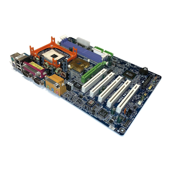
Page 11: Ga-8S648(-L) Motherboard Layout
F_AUDIO SiS 648 AUX_IN IDE1 SUR_CEN PCI1 CODEC PCI2 AGP 8X BIOS PCI3 SiS 963L DDR 400 RTL8101L PCI4 P4 Titan PCI5 SPDIF_O F_U SB2 MODEM SYS _FAN F_PANEL F_U SB1 PWR_LED ) For GA-8S648-L only - 7 - Introduction... -
Page 12: Block Diagram
KB/Mouse 24 MHz (33MHz) 6 USB ATA33/66/100/133 33 MHz Ports IDE Channels Ports ZCLK (66/133MHz) PCICLK (33MHz) CPUCLK+/- (100/133MHz) CLK GEN USBCLK (48MHz) AGPCLK (66MHz) 14.318 MHz HCLK+/- (100/133MHz) 33 MHz ) For GA-8S648-L only GA-8S648(-L) Motherboard - 8 -... - Page 13 - 9 - Introduction...
-
Page 14: Chapter 2 Hardware Installation Process
Step 1 Step 4 Step 4 Step 3 Congratulations you have accomplished the hardware installation! Turn on the power supply or connect the power cable to the power outlet. Continue with the BIOS/ software installation. GA-8S648(-L) Motherboard - 10 -... -
Page 15: Step 1: Install The Central Processing Unit (Cpu)
Step 1: Install the Central Processing Unit (CPU) Before installing the processor, adhere to the following warning: If you do not match the CPU socket Pin 1 and CPU cut edge well, it will cause improper installation. Please change the insert orientation. Please make sure the CPU type is supported by the motherboard. -
Page 16: Step 1-2 : Cpu Cooling Fan Installation
Please refer to CPU cooling fan user's manual for more detail installation procedure. 2. Make sure the CPU fan is plugged to 1. Fasten the cooling fan supporting-base the CPU fan connector, than install onto the CPU socket on the complete. mainboard. GA-8S648(-L) Motherboard - 12 -... -
Page 17: Step 2: Install Memory Modules
Step 2: Install memory modules Before installing the processor and heatsink, adhere to the following warning: Please note that the DIMM module can only fit in one direction due to the one notches. Wrong orientation will cause improper installation. Please change the insert orientation. The motherboard has 3 dual inline memory module (DIMM) sockets. - Page 18 PC's and value desktop SMA systems. With a core voltage of only 2.5 Volts compared to conventional SDRAM's 3.3 volts, DDR memory is a compelling solution for small form factor desktops and notebook applications. GA-8S648(-L) Motherboard - 14 -...
-
Page 19: Step 3: Install Expansion Cards
Step 3: Install expansion cards 1. Read the related expansion card's instruction document before install the expansion card into the computer. 2. Remove your computer's chassis cover, necessary screws and slot bracket from the computer. 3. Press the expansion card firmly into expansion slot in motherboard. 4. -
Page 20: Step 4: Connect Ribbon Cables, Cabinet Wires, And Power Supply
USB 1 If your OS does not support USB controller, please contact OS vendor for possible patch or driver upgrade. For more information please contact your OS or device(s) vendors. ) For GA-8S648FX-L only GA-8S648(-L) Motherboard - 16 -... -
Page 21: Audio Connectors
w Parallel Port and Serial Ports (COMA/COMB) Parallel Port Ø This connector supports 2 standard COM ports (25 pin Female) and 1 Parallel port. Device like printer can be connected to Parallel port ; mouse and modem etc can be connected to Serial ports. COMA COMB Serial Port (9 pin Male) -
Page 22: Step 4-2: Connectors & Jumper Setting Introduction
10) F_AUDIO 2) SYS_FAN 11) SUR_CEN 3) ATX_12V 12) CD_IN 4) ATX 13) AUX_IN 5) IDE1/IDE2 14) SPDIF_O 6) FDD 15) F_USB1/F_USB2 7) PWR_LED 16) CI 8) BAT 17) MODEM 9) F_PANEL ) For GA-8S648FX-L only GA-8S648(-L) Motherboard - 18 -... - Page 23 1) CPU_FAN (CPU FAN Connector) Please note, a proper installation of the CPU cooler is essential to prevent the CPU from running under abnormal condition or damaged by overheating.The CPU fan connector supports Max. current up to 600 mA. Pin No. Definition +12V Sense...
- Page 24 AC power cord should only be connected to your power supply unit after ATX power cable and other related devices are firmly connected to the mainboard. Pin No. Definition 3.3V 3.3V Power Good 5V SB(stand by +5V) +12V 3.3V -12V PS _O N(softO n/ Off) GA-8S648(-L) Motherboard - 20 -...
- Page 25 5) IDE1/ IDE2(IDE1/IDE2 Connector) Please connect first harddisk to IDE1 and connect CDROM to IDE2. The red stripe of the ribbon cable must be the same side with the Pin1. 6) FDD (Floppy Connector) Please connect the floppy drive ribbon cables to FDD. It supports 360K,720K,1.2M,1.44M and 2.88Mbytes floppy disk types.
- Page 26 If you want to erase CM OS... 1.Turn OFF the computer and unplug the power cord. 2.Remove the battery, wait for 30 second. 3.Re-install the battery. 4.Plug the power cord and turn ON the computer. GA-8S648(-L) Motherboard - 22 -...
- Page 27 9) F_PANEL (2x10 pins connector) Please connect the power LED, PC peaker, reset switch and power switch etc of your chassis front panel to the F_PANEL connector according to the pin assignment above. Soft Po wer Speaker Connector Me ssa g e LED /Po w e r / Connector Sleep LED PW -...
- Page 28 Pin No. Definition POWER FrontAudio(R) RearAudio(R) Reserved No Pin FrontAudio (L) RearAudio(L) 11) SUR_CEN Please contact your nearest dealer for optional SUR_CEN cable. Pin No. Definition SUR OUTL SUR OUTR No Pin CENTER_OUT BASS_OUT GA-8S648(-L) Motherboard - 24 -...
- Page 29 12) CD_IN (CD IN, Black) Connect CD-ROM or DVD-ROM audio out to the connector. Pin No. Definition CD-L CD_R 13) AUX_IN (AUX In Connector) Connect other device(such as PCI TV Tunner audio out)to the connector. Pin No. Definition AUX-L AUX_R - 25 - Hardware Installation Process...
- Page 30 F_USB cable, incorrect connection between the cable and connector will make the device unable to work or even damage it. For optional F_USB cable, please contact your local dealer. Pin No. Definition Power Power USB DX- USB Dy- USB DX+ USB Dy+ No Pin GA-8S648(-L) Motherboard - 26 -...
- Page 31 17) MODEM Please contact your nearest dealer for optional Modem card. Pin No. Definition VDD33 AC OUT AC BCK +12V AC DIN VAUX33 AC DOUT AC SYNC AC RSTB No Pin ) For GA-8S648-L only - 27 - Hardware Installation Process...
- Page 32 GA-8S648(-L) Motherboard - 28 -...
-
Page 33: Chapter 3 Bios Setup
Chapter 3 BIOS Setup BIOS Setup is an overview of the BIOS Setup Program. The program that allows users to modify the basic system configuration. This type of information is stored in battery-backed CMOS RAM so that it retains the Setup information when the power is turned off. ENTERING SETUP Powering ON the comput e r and pressing <Del>... -
Page 34: The Main Menu (For Example: Bios Ver. F1)
GETTING HELP Main Menu The on-line description of the highlighted setup function is displayed at the bottom of the screen. Status Page Setup Menu / Option Page Setup Menu Press F1 to pop up a small help window that describes the appropriate keys to use and the possible selections for the highlighted item. -
Page 35: Integrated Peripherals
Integrated Peripherals This setup page includes all onboard peripherals. Power Manag ement Setup This setup page includes all the items of Green function features. PnP/PCI Configurations This setup page includes all the configurations of PCI & PnP ISA resources. PC Health Status This setup page is the System auto detect Temperature, voltage, fan, speed. -
Page 36: Standard Cmos Features
Standard CMOS Features CMOS Setup Utility -Copy right (C) 1984-2003 Aw ard Softw are Standard CMOS Features Date (mm:dd:y y ) Fri, May 3 2002 Item Help Time (hh:mm:ss) 17:56:23 Menu Lev el u Change the day , month, }IDE Primary Master None y ear }IDE Primary Slav e... - Page 37 C Time The times format in <hour> <mi n ute> <second>. The time is calculated base on the 24-hour military- time clock. For example, 1 p.m. is 13:00:00. C IDE Pri mary Master, S lave / IDE Secondary Master, Slave The category identifies the types of hard disk from drive C to F that has been installed in the computer.
-
Page 38: Base Memory
C Floppy 3 Mode Support (for J apan Area) Normal Floppy Driv e. (Default v alue) 8Disabled 8Driv e A Driv e A is 3 mode Floppy Driv e. 8Driv e B Driv e B is 3 mode Floppy Driv e. Driv e A &... -
Page 39: Advanced Bios Features
Advanced BIOS Features CMOS Setup Utility -Copy right (C) 1984-2003 Aw ard Softw are Adv anced BIOS Features First Boot Dev ice [Floppy ] Item Help Second Boot Dev ice [HDD-0] Menu Lev el u Third Boot Dev ice [CDROM] Select Boot Dev ice Boot Up Floppy Seek [Disabled]... -
Page 40: Password Check
Select y our boot dev ice priority by HDD-0~3. 8HDD-0~3 Select y our boot dev ice priority by SCSI. 8SCSI Select y our boot dev ice priority by CDROM. 8CDROM Select y our boot dev ice priority by ZIP. 8ZIP Select y our boot dev ice priority by USB-FDD. -
Page 41: Integrated Peripherals
[201] Midi Port Address [330] Midi Port IRQ [10] higf: Mov e Enter:Select +/-/PU/PD:Value F10:Sav e ESC:Ex it F1:General Help F5:Prev ious Values F6:Fail-Safe Defaults F7:Optimized Defaults Figure 4: Integrated Peripherals ) For GA-8S648-L only - 37 - BIOS Setup... -
Page 42: Ac97 Audio
C IDE1 Conductor Cable Will be automatically detected by BIOS. (Default Value) 8Auto Set IDE1 Conductor Cable to ATA66/100/133 (Please make sure y our IDE 8ATA66/100/133 dev ice and cable is compatible w ith ATA66/100/133). Set IDE1 Conductor Cable to ATA33 (Please make sure your IDE dev ice and 8ATA33 cable is compatible w ith ATA33). -
Page 43: Onboard Serial Port
Enable onboard LPT port and address is 378/IRQ7. (Default Value) 8378/IRQ7 Enable onboard LPT port and address is 278/IRQ5. 8278/IRQ5 Disable onboard LPT port. 8Disabled Enable onboard LPT port and address is 3BC/IRQ7. 83BC/IRQ7 ) For GA-8S648-L only - 39 - BIOS Setup... - Page 44 CParallel Port Mode Using Parallel port as Standard Parallel Port. (Default Value) 8SPP Using Parallel port as Enhanced Parallel Port. 8EPP Using Parallel port as Ex tended Capabilities Port. 8ECP Using Parallel port as ECP & EPP mode. 8ECP+EPP CECP Mode Use DMA Set ECP Mode Use DMA to 3.
-
Page 45: Power Management Setup
Power Management Setup CMOS Setup Utility -Copy right (C) 1984-2003 Aw ard Softw are Pow er Management Setup ACPI Suspend Ty pe [S1(POS)] Item Help Soft-Off by PWR_BTTN [Off] Menu Lev el u Sy stem After AC Back [Off] [S1] IRQ [3-7, 9-15], NMI [Enabled] Set suspend ty pe to... -
Page 46: Resume By Alarm
C IRQ [3-7, 9-15], NMI Disable this function. 8Disabled Enable this function. (Default v alue) 8Enabled C ModemRingOn Disable Modem Ring on function. 8Disabled Enable Modem Ring on function. (Default Value) 8Enabled C PME Event Wake Up Disable this function. 8Disabled Enable PME Ev ent Wake up. -
Page 47: Pnp/Pci Configurations
PnP/PCI Configurations CMOS Setup Utility -Copy right (C) 1984-2003 Aw ard Softw are PnP/PCI Configurations PCI 4 IRQ Assignment [Auto] Item Help PCI 1/5 IRQ Assignment [Auto] Menu Lev el u PCI 2 IRQ Assignment [Auto] PCI 3 IRQ Assignment [Auto] higf: Mov e Enter:Select +/-/PU/PD:Value F10:Sav e... -
Page 48: Pc Health Status
PC Health Status CMOS Setup Utility -Copy right (C) 1984-2003 Aw ard Softw are PC Health Status Reset Case Open Status [Disabled] Item Help Menu Lev el u Case Opened VCORE 1.778V [Disabled] VCC18 1.856V Don’ t reset case +3.3V 3.2V open status 4.945V... -
Page 49: Cpu Warning Temperature
C Current System / CPU Temperature 8Detec t Sy stem /CPU temperature automatic ally . C Current CPU/SYSTEM FAN Speed (RPM) 8Detec t CPU/Sy stem Fan speed status automatic ally . C CPU Warning Temperature Don't monitor CPU's temperature. (Default v alue) 8Disabled Alarm w hen CPU current temperature ov er than 60°/140°F. -
Page 50: Frequency/Voltage Control
Frequency/Voltage Control CMOS Setup Utility -Copy right (C) 1984-2003 Aw ard Softw are Frequency /Voltage Control CPU Clock Ratio [10X] Item Help Menu Lev el u Linear Frequency Control [Disabled] x CPU Clock (MHz) x DRAM Clock (MHz) AUTO AGP/PCI Clock Control [AUTO] x AGP Clock (MHz) x PCI Clock (MHz) - Page 51 C DRAM Clock (MHz) 8Please set DRAM Clock according to y our requirement. If y ou use DDR266 DRAM module, please set "DRAM Clock(MHz)" to Auto or 266. If y ou use DDR333 DRAM module, please set "DRAM Clock(MHz)" to Auto or 333. Incorrect using it may cause y our sy stem broken.
-
Page 52: Top Performance
Top Performance CMOS Setup Utility -Copy right (C) 1984-2003 Aw ard Softw are }Standard CMOS Features Top Performance }Adv anced BIOS Features Load Fail-Safe Defaults Top Performance }Integrated Peripherals Load Optimized Defaults }Pow er Management Setup Set Superv isor Passw ord Disabled....[ n] }PnP/PCI Configurations Set User Passw ord... -
Page 53: Load Fail-Safe Defaults
Load Fail-Safe Defaults CMOS Setup Utility -Copy right (C) 1984-2003 Aw ard Softw are }Standard CMOS Features Top Performance }Adv anced BIOS Features Load Fail-Safe Defaults }Integrated Peripherals Load Optimized Defaults }Pow er Management Setup Set Superv isor Passw ord Load Fail-Safe Defaults? (Y/N)?Y }PnP/PCI Configurations Set User Passw ord... -
Page 54: Load Optimized Defaults
Load Optimized Defaults CMOS Setup Utility -Copy right (C) 1984-2003 Aw ard Softw are }Standard CMOS Features Top Performance }Adv anced BIOS Features Load Fail-Safe Defaults }Integrated Peripherals Load Optimized Defaults }Pow er Management Setup Set Superv isor Passw ord Load Optimized Defaults? (Y/N)?Y }PnP/PCI Configurations Set User Passw ord... -
Page 55: Set Supervisor/User Password
Set Supervisor/User Password CMOS Setup Utility -Copy right (C) 1984-2003 Aw ard Softw are }Standard CMOS Features Top Performance }Adv anced BIOS Features Load Fail-Safe Defaults }Integrated Peripherals Load Optimized Defaults }Pow er Management Setup Set Superv isor Passw ord Enter Password: }PnP/PCI Configurations Set User Passw ord... -
Page 56: Save & Exit Setup
Save & Exit Setup CMOS Setup Utility -Copy right (C) 1984-2003 Aw ard Softw are }Standard CMOS Features Top Performance }Adv anced BIOS Features Load Fail-Safe Defaults }Integrated Peripherals Load Optimized Defaults }Pow er Management Setup Set Superv isor Passw ord }PnP/PCI Configurations Set User Passw ord Save to CMOS and EXIT (Y/N)? Y... -
Page 57: Exit Without Saving
Exit Without Saving CMOS Setup Utility -Copy right (C) 1984-2003 Aw ard Softw are }Standard CMOS Features Top Performance }Adv anced BIOS Features Load Fail-Safe Defaults }Integrated Peripherals Load Optimized Defaults }Pow er Management Setup Set Superv isor Passw ord }PnP/PCI Configurations Set User Passw ord Quit Without Saving ( Y/N)? N... - Page 58 GA-8648(-L) Motherboard - 54 -...
-
Page 59: Chapter 4 Technical Reference
Revision History Chapter 4 Technical Reference @ BIOS Introduction Gigabyte announces @ BIOS Windows BIOS live update utility Have you ever updated BIOS by yourself? Or like many other people, you just know what BIOS is, but always hesitate to update it? Because you think updating newest BIOS is unnecessary and actually you don’... -
Page 60: Easy Tune Tm 4 Introduction
*Some Gigabyte products are not fully supported by EasyTune 4. Please find the products supported list in the web site. *Any "Overclocking action" is at user's risk, Gigabyte Technology will not be responsible for any damage or instability to your processor, motherboard, or any other components. -
Page 61: Flash Bios Method Introduction
Flash BIOS Method Introduction Method 1: Q-Flash A. What is Q-Flash Utility? Q-Flash utility is a pre-O.S. BIOS flash utility enables users to update its BIOS within BIOS mode, no more fooling around any OS. B. How to use Q-Flash? a. - Page 62 Are you sure to update BIOS? [Enter] to contiune Or [ESC] ot abort... !Press Enter to Run. !! COPY BIOS Completed -Pass !! Please press any key to continue Congratulation! You have completed the flashed and now can restart system. GA-8S648(-L) Motherboard - 58 -...
- Page 63 Method 2: @ BIOS Utility If you don't have DOS boot disk, we recommend that you used Gigabyte @BIOS program to flash BIOS. 2.Click"Start"-"Programs"- Press here. "GIGABYTE"-"@BIOS" 1.Click "@BIOS" 3.Click "P". 4.Click here. 5. Please select @BIOS sever site, then Click "OK". Methods and steps: I.
- Page 64 In method I, if the BIOS file you need cannot be found in @BIOS server, please go onto Gigabyte's web site for downloading and updating it according to method II. d. Please note that any interruption during updating will cause system unbooted GA-8S648(-L) Motherboard - 60 -...
-
Page 65: 4-/6-Channel Audio Function Introuction
Revision History 2-/4-/6-Channel Audio Function Introuction The installation of windows 98SE/2K/ME/XP is very simple. Please follow next step to install the function! Stereo Speakers Connection and Settings: We recommend that you use the speaker with amplifier to acqiire the best sound effect if the stereo output is applied. - Page 66 4 speakers out put". Disable "Only SURROUND-KIT", and press "OK". When the "Environment settings" is "None", the sound would be performed as stereo mode (2 channels output). Please select the other settings for 4 channels output. GA-8S648(-L) Motherboard - 62 -...
- Page 67 Basic 6 Channel Analog Audio Output Mode Use the back audio panel to connect the audio out- put without any additional module. STEP 1 : Line Out Connect the front channels to "Line Out",the rear Line In channels to "Line In", and the Center/Subwoofer channels to "MIC In".
- Page 68 GIGABYTE unique "Audio Com bo Kit" as picture. STEP 1 : Insert the "SURROUND-KIT" in the back of the case ,and fix it with the screw. STEP 2 : Connect the "SURROUND-KIT" to SUR_CEN on the M/B. GA-8S648(-L) Motherboard - 64 -...
- Page 69 STEP 3 : Connect the front channels to back audio panel's "Line Out", the rear channels to SURROUND-KIT's REAR R/L, and the Center/Subwoofer channels to SURROUND-KIT's SUB CENTER. STEP 4 : Click the audio icon "Sound Effect" from the windows tray at the bottom of the screen. STEP 5 : Select "Speaker Configuration", and choose the "6 channels for 5.1 speakers out put".
- Page 70 Fiber connecting port. 1. Connect the SPDIF output device to the rear bracket of PC, and fix it with screw. 2. Connect SPDIF device to the m otherboard. 3. Connect SPDIF to the SPDIF decoder. GA-8S648(-L) Motherboard - 66 -...
-
Page 71: Xpress Recovery Introduction
Xpress Recovery Introduction What is Xpress Recovery? Xpress Recovery utility is an utility for backing up and restoring O.S. partition. If the hard drive can not work properly, you can restore it to the original state. 1. It supports FAT16¡BBFAT32¡BNTFS Operation System . 2. - Page 72 Press Esc to exit Restore the backup image to the original state. 3.Remove Backup Image: Do you sure to remove backup image? (Y/N) Remove the backup image. 4.Exit and Restart: Exit and restart your computer. GA-8S648(-L) Motherboard - 68 -...
- Page 73 - 69 - Technical Reference...
- Page 74 GA-8S648(-L) Motherboard - 70 -...
-
Page 75: Chapter 5 Appendix
Revision History Chapter 5 Appendix Install Drivers Pictures below are shown in Windows XP (CD ver. 2.22) Insert the driver CD-title that came with your motherboard into your CD-ROM drive, the driver CD-title will auto start and show the installation guide. If not, please double click the CD-ROM device icon in "My computer", and execute the setup.exe. - Page 76 Service Pack. After install Windows Service Pack, it will show a question mark "?" in "Universal Serial Bus controller" under "Device Manager". Please remove the question mark and restart the system (System will auto-detect the right USB2.0 driver). ) For GA-8S648-L only GA-8S648(-L) Motherboard - 72 -...
-
Page 77: Software Application
SOFTWARE APPLICATION This page reveals the value-added software developed by Gigabyte and its worldwide partners. n Gigabyte Windows Utilities Manager(GWUM) This utility can integrate the Gigabyte's applications in the system tray. n Gigabyte Management Tool(GMT) A useful tool which can manage the computer via the network. n EasyTune4 Powerful utility that integrates the overclocking and hardware monitoring functions. -
Page 78: Software Information
SOFTWARE INFORMATION This page list the contects of softwares and drivers in this CD title. HARDWARE INFORMATION This page lists all device you have for this motherboard. CONTACT US Please see the last page for details. GA-8S648(-L) Motherboard - 74 -... - Page 79 Below is a collection of general asked questions. To check general asked questions based on a specific motherboard model, please log on to http://tw.giga-byte.com/faq/faq.htm Question 1: I cannot see some options that were included in previous BIOS after updating BIOS. Why? Answer: Some advanced options are hidden in new BIOS version.
- Page 80 USB Over Current pin in the Front USB Panel. If the cable is your own cable, please remove it from this pin and do not connect any of your own cables to GA-8S648(-L) Motherboard - 76 -...
- Page 81 Question 10: Sometimes I hear different continuous beeps from computer after system boots up. What do these beeps usually stand for? Answer: The beep codes below may help you identify the possible computer problems. However, they are only for reference purposes. The situations might differ from case to case. gAMI BIOS Beep Codes *Computer gives 1 short beep when system boots successfully.
- Page 82 Answer:Please set in the BIOS as follow: 1. Advanced BIOS features-->(SATA)/RAID/SCSI boot order: "SCSI" 2. Advanced BIOS features--> First boot device: "SCSI" Then it depends on the mode(RAID or ATA) that you need to set in RAID/ SCSI BIOS. GA-8S648(-L) Motherboard - 78 -...
-
Page 83: Troubleshooting
Troubleshooting If you encounter any trouble during boot up, please follow the troubleshooting procedures . START Turn off the power and unplug the AC power cable, then remove all of the add-on cards and cables from motherboard. Please isolate Please make sure motherboard & chassis are not short ? the short pin. - Page 84 If the above procedure unable to solve your problem, please contact with your local retailer or national distributor for help. Or, you could submit your question to the service mail via Gigabyte website technical support zone (http://www.gigabyte.com.tw). The appropriate response will be provided ASAP. GA-8S648(-L) Motherboard - 80 -...
- Page 85 Technical Support/RMA Sheet Customer/Country: Company: Phone No.: Contact Person: E-mail Add. : Model name/Lot Number: PCB revision: BIOS version: O.S./A.S.: Hardware Mfs. Model name Size: Driver/Utility: Configuration C P U Memory Brand Video Card Audio Card CD-ROM / DVD-ROM Modem Network AMR / CNR Keyboard...
- Page 86 E C C Error Checking and Correcting E M C Electromagnetic Compatibility Enhanced Parallel Port Electrostatic Discharge Floppy Disk Device Front Side Bus Hard Disk Device Integrated Dual Channel Enhanced Interrupt Request to be continued..GA-8S648(-L) Motherboard - 82 -...
- Page 87 Acronyms Meaning IOAPIC Input Output Advanced Programmable Input Controller Industry Standard Architecture Local Area Network Input / Output Logical Block Addressing Light Emitting Diode MH z Megahertz MIDI Musical Instrument Digital Interface Memory Translator Hub Memory Protocol Translator Network Interface Card Operating System Original Equipment Manufacturer PCI A.G.P.
- Page 88 GA-8S648(-L) Motherboard - 84 -...
- Page 89 - 85 - Memo...
- Page 90 GA-8S648(-L) Motherboard - 86 -...
- Page 91 - 87 - Memo...
- Page 92 GA-8S648(-L) Motherboard - 88 -...
- Page 93 - 89 - Memo...
- Page 94 GA-8S648(-L) Motherboard - 90 -...
- Page 95 - 91 - Memo...
- Page 96 CONTACT US Contact us via the information in this page all over the world. — Taiwan — The Netherlands Gigabyte Technology Co., Ltd. Giga-Byte Technology B.V. Address: No.6, Bau Chiang Road, Hsin-Tien, Taipei Address: Postbus 1385, 5602 BJ, Eindhoven, The Hsien, Taiwan, R.O.C.
Need help?
Do you have a question about the GA-8S648 and is the answer not in the manual?
Questions and answers