
Related Manuals for Gigabyte GA-8S649MF-FS


Summary of Contents for Gigabyte GA-8S649MF-FS
- Page 1 GA-8S649MF-FS Intel Pentium 4 LGA775 Processor Motherboard ® ® User's Manual Rev. 1001...
-
Page 2: Atx_12V
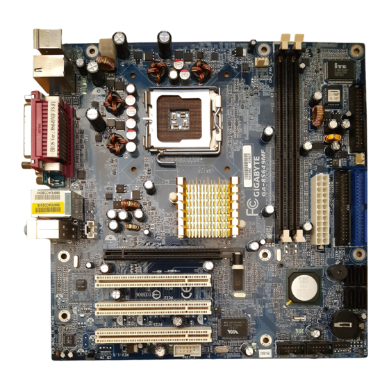
GA-8S649MF-FS Motherboard Layout CPU_FAN KB_MS ATX_12V IT8705 USB_1394 BIOS SPDIF_O LGA775 COMA AUX_IN SiS 649 AUDIO F_AUDIO PCIE_16 Buzzer PCI1 RTL8201CL SiS 965 PCI2 PCI3 BATTERY SAFE MODE VT6307 F_USB1 F_USB2 CLR_CMOS CODEC F_1394 F_PANEL - 2 -... -
Page 3: Block Diagram
Block Diagram LGA775 CPUCLK+/-(200MHz) Processor PCI- ECLK(100MHz) System Bus 800MHz DDR400/333/266MHz DIMM PCI Express x16 DDR RAM SiS 649 MCHCLK (200MHz) 66MHz 33MHz 14.318MHz 48MHz 4 Serial ATA ATA33/66/100 IDE Channels PCI Bsu SiS 965 Floppy VT6307 LPT Port IT 8705 8210CL COM Port BIOS... -
Page 4: Feature Summary
CPU / System fan speed detection CPU warning temperature CPU / System fan failure warning BIOS Use of licensed AWARD BIOS Additional Features Supports @BIOS Form Factor Micro ATX form factor; 24.4 cm x 24.4cm GA-8S649MF-FS Motherboard - 4 -... - Page 5 I/O Back Panel Introduction PS/2 Keyboard and PS/2 Mouse Connector This connector supports standard PS/2 PS/2 Mouse Connector keyboard and PS/2 mouse. (6 pin Female) PS/2 Keyboard Connector (6 pin Female) USB / 1394 Connector Before you connect your device(s) into USB connector(s), please make sure your 1394 device(s) such as USB keyboard,mouse,...
-
Page 6: Audio Connectors
Parallel Port, Serial Port and SPDIF (LPT/COMA/SPDIF) Parallel Port This connector supports 1 standard COM port (25 pin Female) ,1 Parallel port and 1 SPIDF. Device like printer can be connected to Parallel port; mouse and modem etc can be connected to Serial ports. The SPDIF output is capable of providing digital audio to external speakers or compressed AC3 data to an external Dolby Digital Decoder. -
Page 7: Installation Of The Cpu And Heatsink
CPU into position. (Grasping the CPU firmly between your thumb and forefinger, carefully place it into the socket in a straight and downwards motion. Avoid twisting or bending motions that might cause damage to the CPU dur- ing installation.) GA-8S649MF-FS Motherboard - 7 -... -
Page 8: Installation Of The Heatsink
1-3-2 Installation of the Heatsink Male Push Pin The top of Female Push Pin Female Push Pin Fig.1 Fig. 2 Please apply an even layer of heatsink paste on (Turning the push pin along the direction of arrow the surface of the installed CPU. is to remove the heatsink, on the contrary, is to install.) Please note the direction of arrow sign on the male... -
Page 9: Installation Of Memory
DIMM slot. Then push it down. 3. Close the plastic clip at both edges of the DIMM slots to lock the DIMM module. Reverse the installation steps when you wish to remove the DIMM module. GA-8S649MF-FS Motherboard - 9 -... -
Page 10: Table Of Contents
Connectors Introduction 1) ATX_12V 8) F_PANEL 2) ATX (Power Connector) 9) F_AUDIO 3) CPU_FAN 10) AUX_IN 4) SYS_FAN 11) F_USB1 / F_USB2 5) FDD 12) F_1394 6) IDE1 / IDE2 13) CLR_CMOS 7) S_ATA0 / S_ATA1 / S_ATA2 / S_ATA3 14) SAFE MODE 15) Battery - 10 -... - Page 11 ; Otherwise, please do not remove it. Pin No. Definition +12V +12V Pin No. Definition 3.3V 3.3V Power Good 5V SB(stand by +5V) +12V +12V 3.3V(Only for 24pins ATX) 3.3V -12V PS_ON(soft On/Off) GA-8S649MF-FS Motherboard - 11 -...
-
Page 12: Sys_Fan
3/4) CPU_FAN / SYS_FAN (Cooler Fan Power Connector) The cooler fan power connector supplies a +12V power voltage via a 3-pin/4-pin (only for CPU_FAN) power connector and possesses a foolproof connection design. Most coolers are designed with color-coded power connector wires. A red power connector wire indicates a positive connection and requires a +12V power voltage. -
Page 13: S_Ata0 / S_Ata1 / S_Ata2 / S_Ata3
7) S_ATA0 / S_ATA1 / S_ATA2 / S_ATA3 Serial ATA can provide 150MB/s transfer rate. Please refer to the BIOS setting for the Serial ATA and install the proper driver in order to work properly. Pin No. Definition GA-8S649MF-FS Motherboard - 13 -... -
Page 14: F_Panel
8) F_PANEL (Front Panel Jumper) Please connect the LED, reset switch and power switch etc. of your chassis front panel to the F_PANEL connector according to the pin assignment below. Message LED/ Power Sleep LED Switch IDE Hard Disk Reset Switch Active LED HD (IDE Hard Disk Active LED) Pin 1: LED anode(+) -
Page 15: F_Audio
FrontAudio(R) Rear Audio (R)/ Return R No Pin FrontAudio (L) Rear Audio (L)/ Return L 10) AUX_IN Connect other device (such as PCI TV Tuner audio out) to the connector. Pin No. Definition AUX-L AUX-R GA-8S649MF-FS Motherboard - 15 -... -
Page 16: F_Usb1 / F_Usb2
11) F_ USB1 / F_USB2 (Front USB Connector) Be careful with the polarity of the front USB connector. Check the pin assignment carefully while you connect the front USB cable, incorrect connection between the cable and connector will make the device unable to work or even damage it. For optional front USB cable, please contact your local dealer. -
Page 17: Clr_Cmos
Short :Clear CMOS 14) SAFE MODE 1-2 Short : Normal (Default) 2-3 Short :SAFE MODE System runs into BIOS setup screen directly without POST Open :Recovery System runs into floppy and proceed the recovery routine GA-8S649MF-FS Motherboard - 17 -... -
Page 18: Hardware Installation
15) Battery Danger of explosion if battery is incorrectly replaced. Replace only with the same or equivalent type recommended by the manufacturer. Dispose of used batteries according to the manufacturer's instructions. If you want to erase CMOS... 1.Turn OFF the computer and unplug the power cord. 2.Remove the battery, wait for 30 seconds. - Page 19 Chapter 2 BIOS Setup BIOS (Basic Input and Output System) includes a CMOS SETUP utility which allows user to configure required settings or to activate certain system features. The CMOS SETUP saves the configuration in the CMOS SRAM of the motherboard. When the power is turned off, the battery on the motherboard supplies the necessary power to the CMOS SRAM.
- Page 20 Fail-Safe Defaults refers to the value of the system parameters with which the system would be in safe configuration. Load Optimized Defaults Optimized Defaults refers to the value of the system parameters with which the system would be in best performance configuration. GA-8S649MF-FS Motherboard - 28 -...
- Page 21 Set Supervisor Password Change, set, or disable password. It allows you to limit access to the system and Setup, or just to Setup. Set User Password Change, set, or disable password. It allows you to limit access to the system. Save &...
-
Page 22: Standard Cmos Features
Hard drive information should be labeled on the outside drive casing. Enter the appropriate option based on this information. Cylinder Number of cylinders Head Number of heads Precomp Write precomp Landing Zone Landing zone Sector Number of sectors GA-8S649MF-FS Motherboard - 30 -... - Page 23 Drive A The category identifies the types of floppy disk drive A that has been installed in the computer. None No floppy drive installed 360K, 5.25" 5.25 inch PC-type standard drive; 360K byte capacity. 1.2M, 5.25" 5.25 inch AT-type high-density drive; 1.2M byte capacity (3.5 inch when 3 Mode is Enabled).
-
Page 24: Advanced Bios Features
USB-ZIP Select your boot device priority by USB-ZIP. USB-CDROM Select your boot device priority by USB-CDROM. USB-HDD Select your boot device priority by USB-HDD. Select your boot device priority by LAN. Disabled Disabled this function. GA-8S649MF-FS Motherboard - 32 -... - Page 25 Boot Up Floppy Seek During POST, BIOS will determine if the installed floppy disk drive is 40 or 80 tracks. 360K type is 40 tracks 720K, 1.2M and 1.44M are all 80 tracks. Disabled BIOS will not search for the type of floppy disk drive by track number. Note that there will not be any warning message if the drive installed is 360K.
-
Page 26: Integrated Peripherals
Disable onboard 2nd channel IDE port. AC97 Audio Enabled Autodetect AC97 audio function. (Default value) Disabled Disable AC97 audio function. Onboard LAN device Enabled Enable Onboard LAN device function. (Default value) Disabled Disable this function. GA-8S649MF-FS Motherboard - 34 -... - Page 27 USB Controller Enabled Enable USB Controller. (Default value) Disabled Disable USB Controller. USB Legacy Support Enabled Enable USB Legacy Support. Disabled Disable USB Legacy Support. (Default value) Onboard 1394 Function Enabled Enable onborad 1394 function. (Default value) Disabled Disable onboard 1394 function. SiS Serial ATA Controller Enabled Enable SiS Serial ATA Controller.(Default value)
-
Page 28: Power Management Setup
Enable ModemRingOn function. (Default value) PME Event Wake Up Disabled Disable this function. Enabled Enable PME Event Wake up. (Default value) USB Device Wake-up from S3 Disabled Disable this function. Enabled Enable USB device wake-up from S3. (Default value) GA-8S649MF-FS Motherboard - 36 -... - Page 29 Power On by Keyboard Password Enter one to five characters to set the Keyboard Power On password. Disabled Disabled this function. (Default value) Any Key Press any key to turn on the computer. Power On by Mouse Disabled Disable this function. (Default value) Enabled Move or click the mouse to turn on the computer.
- Page 30 Auto assign IRQ to PCI 3. (Default value) 3,4,5,7,9,10,11,12,14,15 Set IRQ 3,4,5,7,9,10,11,12,14,15 to PCI 3. PCI 1 IRQ Assignment Auto Auto assign IRQ to PCI 1. (Default value) 3,4,5,7,9,10,11,12,14,15 Set IRQ 3,4,5,7,9,10,11,12,14,15 to PCI 1. GA-8S649MF-FS Motherboard - 38 -...
-
Page 31: Pc Health Status
PC Health Status CMOS Setup Utility-Copyright (C) 1984-2005 Award Software PC Health Status Vcore Item Help +3.3V Menu Level +12V [Disabled] DDR 2.5V Don’t reset case Current System Temperature open status Current CPU Temperature Current CPU FAN Speed 4687 RPM [Enabled] Current SYSTEM FAN Speed Clear case open status... - Page 32 Set DRAM RAS to CAS Delay to 3T/2T/4T/5T. (Default value:5T) CPU Clock Ratio (MHz) This setup option will be automatically assigned by CPU detection. The option will display "Locked" and read only if the CPU ratio is not changeable. GA-8S649MF-FS Motherboard - 40 -...
-
Page 33: Load Optimized Defaults
Load Fail-Safe Defaults CMOS Setup Utility-Copyright (C) 1984-2005 Award Software Standard CMOS Features Load Fail-Safe Defaults Advanced BIOS Features Load Optimized Defaults Integrated Peripherals Set Supervisor Password Power Management Setup Set User Password Load Fail-Safe Defaults (Y/N)? N PnP/PCI Configurations Save &... -
Page 34: Set Supervisor/User Password
Setup Menu. If you select "Setup" at "Password Check" in Advance BIOS Features Menu, you will be prompted only when you try to enter Setup. GA-8S649MF-FS Motherboard - 42 -... -
Page 35: Exit Without Saving
2-12 Save & Exit Setup CMOS Setup Utility-Copyright (C) 1984-2005 Award Software Standard CMOS Features Load Fail-Safe Defaults Advanced BIOS Features Load Optimized Defaults Integrated Peripherals Set Supervisor Password Power Management Setup Set User Password Save to CMOS and EXIT (Y/N)? Y PnP/PCI Configurations Save &...
Need help?
Do you have a question about the GA-8S649MF-FS and is the answer not in the manual?
Questions and answers