Table of Contents
Advertisement
Quick Links
SPECIFICATIONS:
Model ......................................... 500-1000-10
Frequency Range ....................... 390 To 650 MHz
*Gain .......................................... 12 To 13 dBic
Front to back .............................. 20 dB Nominal
Beamwidth ............................... 46° Nominal
Feed Impedance. ....................... 50 Ohms
Maximum VSWR ........................ 1.5:1
Input Connector .......................... "N" Female
Power Handling .......................... 1 kW
FEATURES:
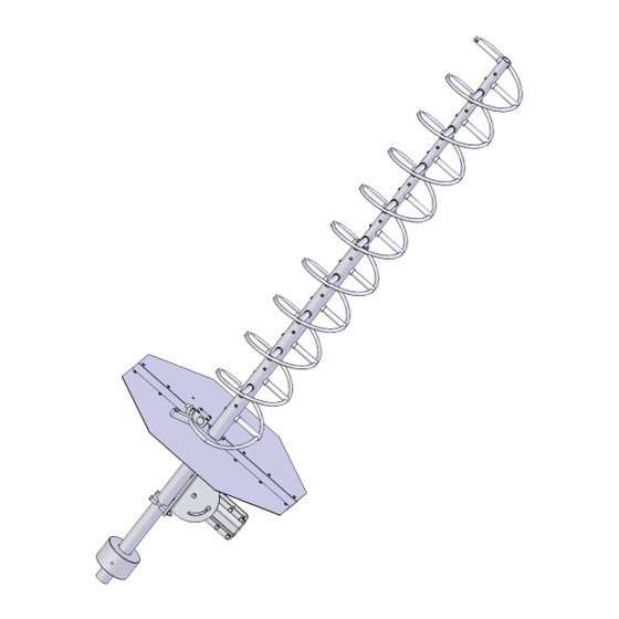
The M2 500-1000-10 Helix antenna model is designed to meet environmental condition specified by MIL-STD-
810 and offers performance characteristics for specialized fixed and rapid deploy operations within the 500 to 1000 MHz
band. It is perfect for either terrestrial or satellite applications. The antenna is supplied with a manually adjustable Azi-
muth / Elevation mount and a counter weight. The antenna is shipped with the helix assembled less ground plane. The
Finish is gold anodyne plating. The steel adjustable mounting fixture and counterweight are zinc plated. Optional tactical
carrying cases are available. Optional arrays of 2 or more are available. Other frequency ranges and gains are also avail-
able down to 100 MHz. Complete motorized, computer controlled AZ-EL systems are also manufactured by M2.
Where circular polarity is not required but high bandwidth is, M2 offers a line of various log periodic antennas from 5 to
1300 MHz. If it is antenna related, we probably have made it. Call us with your requirements.
M2 Antenna Systems, Inc. 4402 N. Selland Ave. Fresno, CA 93722
M2 Antenna Systems, Inc.
Model No: 500-1000-10
*Subtract 2.14 from dBic for dBdc
Tel: (559) 432-8873 Fax: (559) 432-3059 Web: www.m2inc.com
©2015 M2 Antenna Systems Incorporated
Input Connector .......................... "N" Female
Power Handling .......................... 1 kW
Polarity ........................................ RHCP or LHCP
Mounting ..................................... Adjustable AZ-EL on 2"
Operating Temperature .............. -50 F To 130 F
Wind area / Survival ................... 100 MPH
Weight / Ship Wt. ........................ 20 Lbs./ 80Lbs.
Length ......................................... 52"
Helical dia ................................... 5.1"
3/15/16
Rev.03
Advertisement
Table of Contents

Related Manuals for M2 Antenna Systems 500-1000-10


Summary of Contents for M2 Antenna Systems 500-1000-10
- Page 1 *Subtract 2.14 from dBic for dBdc FEATURES: The M2 500-1000-10 Helix antenna model is designed to meet environmental condition specified by MIL-STD- 810 and offers performance characteristics for specialized fixed and rapid deploy operations within the 500 to 1000 MHz band.
- Page 2 400-600-10 HELICAL ASSEMBLY MANUAL TOOLS REQUIRED: #2 Phillips head screwdriver, 11/32 nut driver and 7/16” socket open end wrench. 1. Unpack the factory assembled HELICAL antenna, the CENTER REFLECTOR PLATE, and the two (2) REFLECTOR HALVES. Attach the Reflector halves to the Center Reflector Plate using 8-32 x 3/4” screws and locknuts. Add the g-plane clamp #1 to the center reflector plate near the center hole using 1/4-20 x 3/4 bolts and lock wash- ers.
- Page 3 400-600-10 FEED ASSEMBLY DETAIL HELICAL SUPORT POST ANTENNA BOOM FEED BLOCK ASSEMBLY CENTER MOUNTING PLATE HELIX FEED SUPORT GROUND PLANE BLOCK 400-600-10 GROUND PLANE DETAIL G-PLANE CLAMP #1 POSITIONING BOLT, 1/4-20 X 3/4 THREADS THROUGH G-PLANE CLAMP #1 AND INTO POSITION- ING HOLE IN REAR BOOM G-PLANE CLAMP #2...
- Page 4 OPTIONAL ELEVATION MOUNTING 4. Assemble the Elevation Bracket hardware as shown on the assembly picture. For the time being set the elevation angle to 0 deg. (mast bracket perpendicular to the antenna). Attach the 1.5” saddle adapter plate to the elevation bracket. Next, using four 1/4-20 x 2 3/4” bolts and locknuts, attach the four saddles loosely to the saddle adapter plate.
- Page 5 400-600-10 PARTS LIST DESCRIPTION HELIX AND MAIN BOOM ......….1 CENTER MOUNTING PLATE, ..... ….1 REFLECTOR PLATE ........….2 G-PLANE CLAMP 1.5” BM DIA #1 ....….1 G-PLANE CRADLE CLAMP 1.5” BM DIA #2 ….1 FEED BLOCK W/ “N” CONN ......….1 FEED SUPPORT BLOCK, .50 X .750 X 2.5”.
Need help?
Do you have a question about the 500-1000-10 and is the answer not in the manual?
Questions and answers