Table of Contents
Advertisement
Quick Links
SPECIFICATIONS:
Model ......................................... 400CP30A
Frequency Range ....................... 395-405 MHz
*Gain .......................................... 16.20 dBIc
Front to back .............................. 22 dB Typical
Ellipticity ..................................... 1.5 dB Typical
Beamwidth ............................... 30
Feed Impedance. ....................... 50 , Unbalanced
Maximum VSWR ........................ 1.6:1 Max
Input Connector .......................... "N" Female
FEATURES:
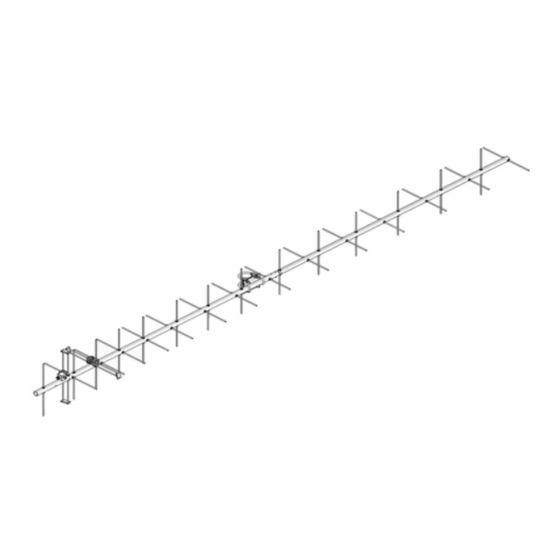
The 400CP30A is a practical sized, yet high performance circular polarized antenna with a remarkably clean pat-
tern. The pattern is important in order to match the antenna's noise temperature with modern low noise preamps. This
antenna is ideal for satellite work but is also excellent for terrestrial uses like ATV, repeater operation, and long haul tropo
DX. The CNC machined driven element module is O-ring sealed and weather tight for low maintenance and long-term
peak performance. Internal connected are encapsulated in a space-age silicone gel that seals out moisture and improves
power handling. The 3/16" 6061-T6 rod elements are centered to minimize interaction and maintain good ellipticity. Insu-
lators are UV stabilized and locked in place with stainless keepers. Rugged construction, uncompromising performance
for the boom length: that's the M
M2 Antenna Systems, Inc. 4402 N. Selland Ave. Fresno, CA 93722
M2 Antenna Systems, Inc.
Model No: 400CP30A
o
circular
*Subtract 2.14 from dBi for dBd
2
400CP30A!
Tel: (559) 432-8873 Fax: (559) 432-3059 Web: www.m2inc.com
©2016 M2 Antenna Systems Incorporated
Power Handling .......................... 600W
Boom Length / Dia ...................... 140-3/4" / 1" Dia
Parasitic Elements ...................... 28, 3/16" Rod
Stacking Distance ....................... 55"
Mast Size .................................... 1-1/2- 2 Inch
Wind area / Survival ................... 1 sq ft.
Weight / Ship Wt. ........................ 5 lbs / 7 lbs UPS
11/22/17
Rev.03
Advertisement
Table of Contents

Related Manuals for M2 Antenna Systems 400CP30A


Summary of Contents for M2 Antenna Systems 400CP30A
- Page 1 *Subtract 2.14 from dBi for dBd FEATURES: The 400CP30A is a practical sized, yet high performance circular polarized antenna with a remarkably clean pat- tern. The pattern is important in order to match the antenna’s noise temperature with modern low noise preamps. This antenna is ideal for satellite work but is also excellent for terrestrial uses like ATV, repeater operation, and long haul tropo DX.
- Page 2 400CP30A ASSEMBLY MANUAL TYPICAL TOOLS REQUIRED: measuring tape, phillips screwdriver, 5/16”, 11/32, 7/16, and 1/2 spin-tite, end wrenches and / or sockets. Heavy duty models may require larger sizes. 1. Lay out the boom sections and assemble using the DIMENSION sheet as a guide for position and hardware.
- Page 3 400CP30A ASSEMBLY MANUAL 7. Generally the balun is installed in one long loop. Attach balun to the block connectors and tighten gently using a 7/16" end wrench. Form the balun coax close to the boom and secure with cable ties (snug but not crushing or kinking the coax).
- Page 4 400CP30A DIMENSION SHEET NOTE: RIGHT HAND CIRCULARITY SHOWN...
- Page 5 400CP30A CP SWITCH DIMENSION SHEET NOTE: RIGHT HAND CIRCULARITY SHOWN...
- Page 6 400CP30A DRIVEN ELEMENT CABLE ROUTES D.E. BLOCK SCREW, 8-32 X 1-1/4”,SS JUNCTION BLOCK PHAS LINE SCREW, 8-32 X 1-1/4” 1/4 WAVE D.E. BALUN D.E. BLOCK D.E. BALUN PHASE LINE 3/4 WAVE 400CP30A POLARITY SWITCH CABLE ROUTES PS DRIVEN ELEMENT BLOK D.E.
- Page 7 400CP30A PARTS & HARDWARE DESCRIPTION..............QTY BOOM SECTION #1, 1.0 X .058 X 60" SOE ....1 BOOM SECTION #2, 1.0 X .058 X 58" SOE ....1 BOOM SECTION #3, 1.0 X .058 X 28.75" ...... 1 BOOM-TO-MAST PLATE, 3 X 4 X 1/8”(M2APT0019)..1 ELEMENT SET , 3/16”...
- Page 8 400CP30A (ASSEMBLED) PARTS & HARDWARE DESCRIPTION ..............………..QTY BOOM SECTION #1, 1.0 X .058 X 60" (ASSEMBLY)……………..1 BOOM SECTION #2, 1.0 X .058 X 58" SOE (ASSEMBLY)……….1 BOOM SECTION #3, 1.0 X .058 X 28.75" (ASSEMBLY)………….1 BOOM-TO-MAST PLATE, 3 X 4 X 1/8”(M2APT0019) ..………….1 U-BOLT AND CRADLE, 2"...
Need help?
Do you have a question about the 400CP30A and is the answer not in the manual?
Questions and answers