Advertisement
Quick Links
INSTALLATION AND MAINTENANCE INSTRUCTIONS
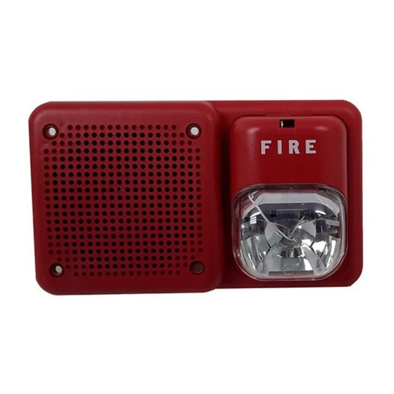
SpectrAlert Selectable Output Outdoor
Wall Speaker/Strobes for
Fire Protective Signaling Systems
Model SP2R1224MCK
U.S. Patent Nos. 5,850,178; 5,598,139; 6,049,446; 6,522,261; 6,661,337; 6,793,375;
6,822,400; 6,833,783; 5,931,569; 6,856,241
Specifications:
Mechanical:
Input Terminals:
Speaker Size:
Grille Size:
Outdoor Back Box:
Electrical:
Operating Temp. Range:
Max. Supervisory Voltage: 50 VDC
For Speaker:
Voltage Input:
Frequency Range:
Input Power Settings:
Sound Output:
S ound output levels are established at Underwriters
Laboratories in their anechoic room. Always use the
sound output specified as UL Anechoic Room when
comparing products.
Model SP2R1224MCK incorporates a new patented voltage booster design that has a more consistent flash bulb voltage over the range of candela selections.
The benefit to the customer is a high quality strobe device.
NOTICE: This manual shall be left with the owner/user of
this equipment.
General Description
The SpectrAlert SP2 series speaker/strobes are designed to
meet the requirements of most agencies governing these
devices, including: NFPA, ADA, The National Fire Alarm
Code, UL. Also, check with your local Authority Having
Jurisdiction for other codes or standards that may apply.
The SpectrAlert SP2 series speakers can be operated with
distribution amplifiers having an output voltage of either
25 volts or 70.7 volts.
The speakers operate at any one of four input power levels.
The output sound level is selected at the time of installa-
tion, but can be changed, if necessary.
D900-40-00
12 to 18 AWG
4 inches (101 mm)
4
13
/
˝ (122 mm)
16
9.22˝ × 5.87˝ × 2.38˝
–40°F to 150.8°F (–40°C to 66°C)
25 volts or 70.7 volts
(nominal)
400 – 4000 Hz
1
/
,
1
/
, 1 and 2 Watts
4
2
firealarmresources.com
For Strobe:
Voltages:
Operational Volt. Ranges: 8–17.5 Volts and 16–33 Volts
Synchronous Applications
with MDL Module:
NOTE: The outdoor speaker/strobe is suitable for use in
dry and wet environments.
Flash Rate:
Selectable Light Outputs: A ll candelas are selectable via
12/24 Volt Applications:
24 Volt Application:
1 5/75 is listed at 15 candela per UL 1971 but will provide
75 candela on axis (straight ahead). 15, 30, 75, or 110 are
rated for that candela.
Listings: UL 1971/1638 (Strobe); UL 1480 (Speaker); NEMA 3R
Note for Strobes: Do not exceed; 1) 8-17.5 or 16-33 voltage
range limit; 2) maximum number of 70 strobe lights when
connecting the MDL Sync module with a maximum line
impedance of 4 ohms per loop and; 3) maximum line imped-
ance as required by the fire alarm control manufacturer.
The speaker is also equipped with a capacitive input to
allow for DC supervision.
The SpectrAlert SP2 series strobe can be installed in systems
using 12 or 24-volt panels having DC or full-wave rectified
(FWR) power supplies. The strobes can also be installed
in applications requiring synchronization (module MDL or
compatible equivalent required) or applications that do not
require synchronization (no module required).
Power Supply Considerations For Strobes
Panels typically supply DC filtered voltage or FWR (full-
wave rectified) voltage. The system design engineer must
calculate the number of units used in a zone based on the
type of panel supply. Be certain the sum of all the device
currents do not exceed the current capability of the panel.
Calculations are based on using the device current found
in Table 2 and must be the current specified for the type of
panel power supply used.
1
3825 Ohio Avenue, St. Charles, Illinois 60174
1-800-SENSOR2, FAX: 630-377-6495
www.systemsensor.com
R egulated 12 DC/FWR and
Regulated 24 DC/FWR
9–17.5 Volts and 17–33 Volts
1 flash per second
a manual slide switch.
15 or 15/75 candela
30, 75, 110 candela
I56-2609-002R
Advertisement

Related Manuals for System Sensor SpectrAlert SP2R1224MCK


Summary of Contents for System Sensor SpectrAlert SP2R1224MCK
- Page 1 INSTALLATION AND MAINTENANCE INSTRUCTIONS SpectrAlert Selectable Output Outdoor Wall Speaker/Strobes for 3825 Ohio Avenue, St. Charles, Illinois 60174 1-800-SENSOR2, FAX: 630-377-6495 Fire Protective Signaling Systems www.systemsensor.com Model SP2R1224MCK U.S. Patent Nos. 5,850,178; 5,598,139; 6,049,446; 6,522,261; 6,661,337; 6,793,375; 6,822,400; 6,833,783; 5,931,569; 6,856,241 For Strobe: Specifications: Mechanical: Voltages: R egulated 12 DC/FWR and Regulated 24 DC/FWR Input Terminals: 12 to 18 AWG Operational Volt. Ranges: 8–17.5 Volts and 16–33 Volts Speaker Size: 4 inches (101 mm) Synchronous Applications Grille Size: ˝ (122 mm) with MDL Module: 9–17.5 Volts and 17–33 Volts...
- Page 2 Wire Sizes Figure 1. Electrical connections: The designer must be sure that the last device on the circuit SPEAKER STROBE has sufficient voltage to operate the device within its rated voltage. When calculating the voltage available to the last device, it is necessary to consider the voltage drop due to the resistance of the wire. The thicker the wire, the less the TO NEXT INPUT FROM voltage drop. Generally, for purposes of determining the SPEAKER OR EOL AMPLIFIER wire size necessary for the system, it is best to consider all of the devices as “lumped” on the end of the supply circuit INPUT FROM TO NEXT POWER SUPPLY STROBE OR EOL (simulates “worst case”).
- Page 3 Table 2. Strobe current draw measurements – 12/24 Volt applications: NOTE: A ll models were only tested at the 8-17.5 and 16-33 Volt-FWR/DC limits. This does not include the 80% low-end or 110% high-end voltage limits. FWR Operating Current–Strobe DC Operating Current–Strobe (mA RMS) (mA RMS) Candela Model No. Setting SP2R1224MCK Speaker/Strobe 15/75 Candela Selections: NOTE: The strobe is not listed for 12V operating voltages Figure 3. For strobe candela selections, adjust slide when set to 30, 75 or 110 candela. Use only those switch located on the rear of the product while settings marked as OK in this chart:...
- Page 4 Figure 4. Knockout plug removal 1. If a rear conduit entry is required, remove the knockout plug using a flat blade screwdriver as shown in Figure 4. Strike sharply with a hammer to pierce the wall of the knockout plug. Move to an adjacent wall section and repeat until the plug falls out. Make sure that the back box is supported adequately during this operation to avoid injury.
Need help?
Do you have a question about the SpectrAlert SP2R1224MCK and is the answer not in the manual?
Questions and answers