Advertisement
Quick Links
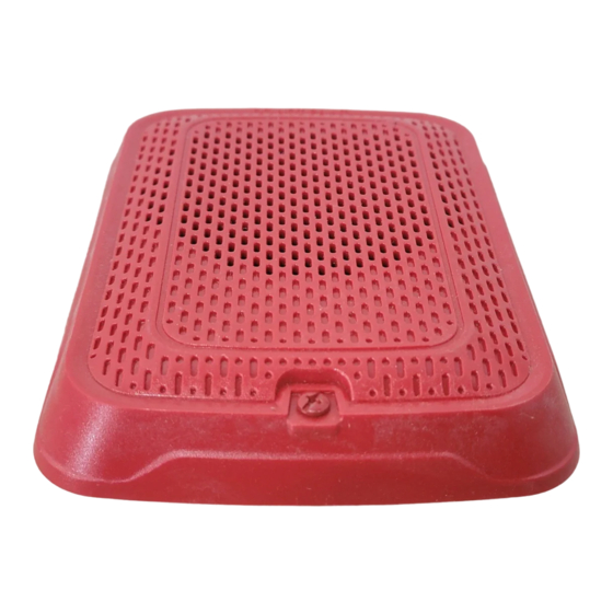
INSTALLATION AND MAINTENANCE INSTRUCTIONS
Dual Voltage Speakers- Wall and
Ceiling Mount
For use with the following models:
Wall Speakers: SPRLA, SPWLA
Ceiling Speakers: SPCRLA, SPCWLA
PRODUCT SPECIFICATIONS
Standard Operating Temperature:
Humidity Range:
Nominal Voltage:
Maximum Supervisory Voltage:
Speaker Frequency Range:
Power Settings:
Input terminal wire gauge:
PRODUCT DIMENSIONS
WALL PRODUCTS
Wall Speaker
CEILING PRODUCTS
Ceiling Speaker
NOTICE: This manual shall be left with the owner/user of this equipment.
BEFORE INSTALLING
Please read the System Sensor Voice Evacuation Application Guide, which
provides detailed information on speaker notification devices, wiring and spe-
cial applications. Copies of this manual are available from System Sensor.
CAN/ULC S524 and NEMA guidelines should be observed.
Important: The notification appliance used must be tested and maintained
following CAN/ULC S536 requirements.
GENERAL DESCRIPTION
System Sensor series of notification appliances offer a wide range of audible
and visible devices for life safety notification. Our line of speakers is designed
to be used at either 25 or 70.7 volts, and operate at any one of four input
power levels. Our speakers are suitable for dry and damp environments.
These products are electrically backwards compatible with previous genera-
tion of System Sensor speakers. With its low total harmonic distortion, the
System Sensor SPL series offers high fidelity sound output. Wall and ceiling
products may be used interchangeably (wall products may be used on ceiling
and ceiling product may be used on wall).
FIRE ALARM SYSTEM CONSIDERATIONS
All wiring must be installed in compliance with the Canadian Electrical Code
(CEC) and applicable local codes. System Sensor recommends installing fire
alarm speakers in compliance with CAN/ULC S524.
WIRING AND MOUNTING
All wiring must be installed in compliance with the Canadian Electric Code
and the local codes as well as the authority having jurisdiction. Wiring must
not be of such length or wire size which would cause the notification appli-
ance to operate outside of its published specifications. Improper connections
can prevent the system from alerting occupants in the event of an emergency.
Wire sizes up to 12 AWG (2.5 mm²) may be used with the mounting plate.
The mounting plate ships with the terminals set for 12 AWG wiring.
Make wire connections by stripping about
wire. Then slide the bare end of the wire under the appropriate clamping plate
and tighten the clamping plate screw.
See Figure 1 for wiring terminals and strip guide reference.
1. Connect the speaker as shown in Figure 1.
32°F to 120°F (0°C to 49°C)
10 to 93% Non-condensing
25 Volts or 70.7 Volts
50 VDC
400 – 4000 Hz
¼, ½, 1, 2 Watts
12 to 18 AWG
Length
Width
6.520" (165 mm)
5.00" (127 mm)
Length
Width
6.8" (173 mm)
N/A
/
" of insulation from the end of the
3
8
6581 Kitimat Road, Unit 6, Mississauga, Ontario L5N-3T5
Depth
0.97" (24.6 mm)
Depth
1.00" (25.4mm)
2. There are two rotary switches on the back of the product. The first switch
is used to select either 25 or 70.7 volts input and the second switch is used to
select the input power of ¼, ½, 1 or 2 watts. (See Figure 2.)
FIGURE 1. WIRING DIAGRAM AND WIRING TERMINALS
Input from
(-)
Amplifier
(+)
Wiring Terminals
1. Negative (-). Line in and out
2. Positive (+). Line in and out
3. Positive (+). Line in and out
FIGURE 2. SPEAKER WATTAGE AND VOLTAGE SETTINGS
1
800/736-7672, FAX: 905-812-0771
www.systemsensor.ca
MOUNTING BOX OPTIONS
SPEAKERS
4" x 4" x 2
/
or deeper
1
8"
Output to
(-)
Next Device or EOL
(+)
NOTE: Do not loop electrical wiring un-
der terminal screws. Wires connecting
the device to the control panel must
be broken at the device terminal con-
nection in order to maintain electrical
supervision.
A0380-00
A0419-01
I56-3577-000
Advertisement

Subscribe to Our Youtube Channel
Related Manuals for System Sensor SPRLA


Summary of Contents for System Sensor SPRLA
-
Page 1: Ceiling Mount
Important: The notification appliance used must be tested and maintained following CAN/ULC S536 requirements. GENERAL DESCRIPTION Output to System Sensor series of notification appliances offer a wide range of audible Input from and visible devices for life safety notification. Our line of speakers is designed Next Device or EOL Amplifier to be used at either 25 or 70.7 volts, and operate at any one of four input... - Page 2 FIGURE 3. SHORTING SPRING A0499-00 AVAILABLE POWER SETTINGS System Sensor offers a wide range of power settings for your life safety needs, including ¼, ½, 1, and 2W. A0500-00 Sound levels data per UL can be found in Table 1. Directional characteristics FIGURE 5.
- Page 3 TAMPER SCREW 2. The wall mount box must be mounted with the up arrow pointing up. (See For tamper resistance, the standard captive screw may be replaced with the Figure 9.) enclosed Torx screw. FIGURE 9. SMBB UP ARROW 1. To remove the captive screw, back out the screw and apply pressure to the back until it disengages from the housing.
- Page 4 THREE-YEAR LIMITED WARRANTY System Sensor warrants its enclosed product to be free from defects in materials and 6, Mississauga, Ontario L5N-3T5. Please include a note describing the malfunction workmanship under normal use and service for a period of three years from date of and suspected cause of failure.
Need help?
Do you have a question about the SPRLA and is the answer not in the manual?
Questions and answers