Advertisement
Quick Links
INSTALLATION AND MAINTENANCE INSTRUCTIONS
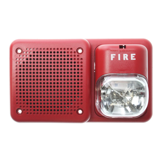
SpectrAlert Selectable Output Series
Wall Speaker/Strobes for
Fire Protective Signaling Systems
For use with models: SP3R1224MC and SP3W1224MC.
U.S. Patent Nos. 5,593,569; 5,914,665; 5,850,178; 5,598,139; 6,049,446; 6,127,935; 6,522,261; 6,856,241
Specifications: Speaker
Mechanical
Input Terminals:
Speaker Size:
Overall Dimensions:
Automatic selection for 12 or 24 volt rated operation (DC or
Full-Wave Rectified)
Electrical
For Strobes
Voltages:
Operational Voltage Ranges:
Synchronous Applications
with MDL Module:
Flash Rate:
Operating Temperature:
Storage Temperature:
Operational Humidity Range: 10 – 93% RH (non-condensing)
Selectable Light Outputs:
12/24 Volt Applications:
NOTICE: This manual shall be left with the owner/user of
this equipment.
General Description
The SpectrAlert SP3 series speaker/strobes are designed to
meet the requirements of most agencies governing these
devices, including: NFPA, ADA, The National Fire Alarm
Code, UL, CSFM, MEA. Also, check with your local Author-
ity Having Jurisdiction for other codes or standards that
may apply.
The SpectrAlert SP3 series speakers can be operated with
distribution amplifiers having an output voltage of either
25 volts or 70.7 volts.
The speakers operate at any one of four input power levels.
The output sound level is selected at the time of installa-
tion, but can be changed, if necessary.
The speaker is also equipped with a capacitive input to al-
low for DC supervision.
The SpectrAlert SP3 series strobe can be installed in systems
using 12 or 24-volt panels having DC or full-wave rectified
(FWR) power supplies. The strobes can also be installed
in applications requiring synchronization (module MDL or
compatible equivalent required) or applications that do not
require synchronization (no module required).
D900-42-00
12 to 18 A WG
4 inches (101 mm)
8.25˝ × 4.9˝
Regulated 12 DC/FWR and
Regulated 24 DC/FWR
8-17.5 Volts and 16-33 Volts
9-17.5 Volts and 17-33 Volts
1 flash per second
32° F to 120° F (0° C to 49° C)
–20°C to 70°C
All candelas are selectable
via a manual slide switch.
15 or 15/75 candela
24 Volt Application:
15/75 is listed at 15 candela per UL 1971 but will pro-
vide 75 candela on axis (straight ahead). 15, 30, 75,
or 110 are rated for that candela.
Maximum Supervisory
Voltage (Speaker):
Sound Output:
Sound output levels are established at Underwriters
Laboratories in their reverberant room. Always use
the sound output specified as UL Reverberant Room
when comparing products.
Listings:
Note for Strobes: Do not exceed; 1) 8-17.5 or 16-33 voltage
range limit; 2) maximum number of 70 strobe lights when
connecting the MDL Sync module with a maximum line im-
pedance of 4 ohms per loop and; 3) maximum line imped-
ance as required by the fire alarm control manufacturer.
NOTE: The SP3 Series is suitable for dry and damp
environments.
Power Supply Considerations For Strobes
Panels typically supply DC filtered voltage or FWR (full-
wave rectified) voltage. The system design engineer must
calculate the number of units used in a zone based on the
type of panel supply. Be certain the sum of all the device
currents do not exceed the current capability of the panel.
Calculations are based on using the device current found
in Table 2 and must be the current specified for the type of
panel power supply used.
Wire Sizes
The designer must be sure that the last device on the circuit
has sufficient voltage to operate the device within its rated
voltage. When calculating the voltage available to the last
device, it is necessary to consider the voltage drop due to
the resistance of the wire. The thicker the wire, the smaller
the voltage drop. Generally, for purposes of determining the
wire size necessary for the system, it is best to consider all
of the devices as "lumped" on the end of the supply circuit
(simulates "worst case").
Typical wire size resistance:
18 AWG solid:
Approximately 8 ohms/1,000 ft.
16 AWG solid:
Approximately 5 ohms/1,000 ft.
14 AWG solid:
Approximately 3 ohms/1,000 ft.
12 AWG solid:
Approximately 2 ohms/1,000 ft.
1
3825 Ohio Avenue, St. Charles, Illinois 60174
1-800-SENSOR2, FAX: 630-377-6495
www.systemsensor.com
15,15/75, 30, 75, 110 candela
50 VDC
UL S5512 (Strobe);
UL S4048 (Speaker/Strobe)
I56-2811-000R
Advertisement

Related Manuals for System Sensor SpectrAlert SP3R1224MC


Summary of Contents for System Sensor SpectrAlert SP3R1224MC
- Page 1 INSTALLATION AND MAINTENANCE INSTRUCTIONS SpectrAlert Selectable Output Series Wall Speaker/Strobes for 3825 Ohio Avenue, St. Charles, Illinois 60174 1-800-SENSOR2, FAX: 630-377-6495 Fire Protective Signaling Systems www.systemsensor.com For use with models: SP3R1224MC and SP3W1224MC. U.S. Patent Nos. 5,593,569; 5,914,665; 5,850,178; 5,598,139; 6,049,446; 6,127,935; 6,522,261; 6,856,241 Specifications: Speaker 24 Volt Application: 15,15/75, 30, 75, 110 candela...
- Page 2 Example: Assume you have 10 devices on a zone and each 2. See Figure 2 as an example of how to select a 1⁄4 Watt requires 50 mA average and 2000 Ft. of 14 AWG wiring (to- input when a 25 volt amplifier is being used. Notice that tal length=outgoing+return).
- Page 3 Candela Selections: C. Plug the remaining two holes that will not be used for attachment with the plugs provided. Figure 3. For strobe candela selections, adjust slide switch located on the rear of the product while NOTE: Two drywall screws (provided) may be used to fasten watching the viewing window on the side of the the mounting plate to the wall.
- Page 4 Three-Year Limited Warranty System Sensor warrants its enclosed speaker/strobe to be free from defects in ma- postage prepaid to: System Sensor, Returns Department, RA #__________, 3825 terials and workmanship under normal use and service for a period of three years Ohio Avenue, St.
Need help?
Do you have a question about the SpectrAlert SP3R1224MC and is the answer not in the manual?
Questions and answers