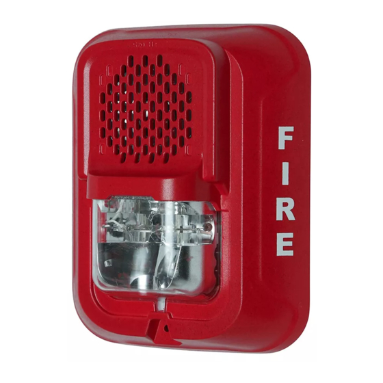
System Sensor L Series Installation And Maintenance Instructions Manual
With led indoor selectable-output speaker strobes
Hide thumbs
Also See for L Series:
- Installation and maintenance instructions manual (11 pages) ,
- Installation and maintenance instructions (4 pages) ,
- Installation and maintenance instruction (4 pages)
Table of Contents
Advertisement
INSTALLATION AND MAINTENANCE INSTRUCTIONS
ENGLISH
L-Series with LED Indoor
Selectable-Output
Speaker Strobes
Manual is for use with the following models:
Wall Mount Speaker Strobes: SPSRLED, SPSRLED-B, SPSRLED-BT, SPSWLED, SPSWLED-B, SPSWLED-BT, SPSRLED-P, SPSWLED-P,
SPSRLED-SP, SPSWLED-CLR-ALERT, SPSWLED-ALERT
Ceiling Mount Speaker Strobes: SPSCRLED, SPSCRLED-B, SPSCRLED-BT, SPSCWLED, SPSCWLED-B, SPSCWLED-P, SPSCWLED-SP,
SPSCWLED-BT, SPSCWLED-T, SPSCWLED-TP, SPSCWLED-CLR-ALERT
Language designators: "-B" are bilingual (English/French). "-BT" is bilingual packaged with a trim ring. "-P" are plain versions (no wording); "TP" is plain
packaged with a trim ring. "-SP" are marked "FUEGO".
Section 1: Introduction .................................................................................................................................................. 2
1.1 Product Specifications .......................................................................................................................................................2
1.2 Dimensions and Mounting Options ...................................................................................................................................2
1.3 Before Installing ................................................................................................................................................................2
1.4 General Description ..........................................................................................................................................................2
1.5 Fire Alarm System Considerations ....................................................................................................................................3
1.6 System Design ..................................................................................................................................................................3
Section 2: Configurations for Notification Appliances ............................................................................................... 4
2.1 Available Candela Settings ...............................................................................................................................................4
2.2 Current Draw and Audibility ratings ...................................................................................................................................5
2.3 Available Power Settings for Speakers .............................................................................................................................5
Section 3: Installation .................................................................................................................................................... 7
3.1 Wiring and Mounting .........................................................................................................................................................7
3.2 Wiring Diagrams ................................................................................................................................................................7
3.3 Install Back Box .................................................................................................................................................................8
3.4 Install Mounting Plate and Appliance ................................................................................................................................8
3.5 Remove a Ceiling Model Appliance ..................................................................................................................................8
3.5.1 Mounting Drawings ........................................................................................................................................................8
3.6 Tamper Screw ...................................................................................................................................................................9
3.7 Test Points ......................................................................................................................................................................10
LED L-series Indoor Speaker Strobes - P/N I56-0024-000 4/15/2024
Table of Contents
3825 Ohio Avenue, St. Charles, Illinois 60174
800/736-7672, FAX: 630/377-6495
www.systemsensor.com
1
Advertisement
Table of Contents

Summary of Contents for System Sensor L Series
-
Page 1: Table Of Contents
INSTALLATION AND MAINTENANCE INSTRUCTIONS ENGLISH L-Series with LED Indoor Selectable-Output 3825 Ohio Avenue, St. Charles, Illinois 60174 800/736-7672, FAX: 630/377-6495 Speaker Strobes www.systemsensor.com Manual is for use with the following models: Wall Mount Speaker Strobes: SPSRLED, SPSRLED-B, SPSRLED-BT, SPSWLED, SPSWLED-B, SPSWLED-BT, SPSRLED-P, SPSWLED-P, SPSRLED-SP, SPSWLED-CLR-ALERT, SPSWLED-ALERT Ceiling Mount Speaker Strobes: SPSCRLED, SPSCRLED-B, SPSCRLED-BT, SPSCWLED, SPSCWLED-B, SPSCWLED-P, SPSCWLED-SP, SPSCWLED-BT, SPSCWLED-T, SPSCWLED-TP, SPSCWLED-CLR-ALERT... -
Page 2: Section 1: Introduction
1.4 General Description System Sensor series of notification appliances offer a wide range of audible and visible devices for life safety notification. Our indoor speaker strobes come with 7 field selectable candela settings. The strobe portion is designed to be used in 24VDC systems. The speaker is designed to be used at either 25 or 70.7 volts, and operate at any one of four input power levels. -
Page 3: Fire Alarm System Considerations
The current draw information for making these calculations can be found in the tables within the manual. For convenience and accuracy, use the voltage drop calculator on the System Sensor website (www.systemsensor.com). -
Page 4: Section 2: Configurations For Notification Appliances
2.1 Available Candela Settings System Sensor offers a wide range of candela settings for your life safety needs. To select your candela output, turn the rotary switch on the back of the product to the desired candela setting. (See Figure 1.) Table 1 shows available candela options. -
Page 5: Current Draw And Audibility Ratings
2.3 Available Power Settings for Speakers System Sensor offers a wide range of power settings for your life safety needs, including ¼, ½, 1, and 2W. Sound levels data per UL 1480 can be found in Table 2. - Page 6 Configurations for Notification Appliances Available Power Settings for Speakers To calculate sound dispersal per UL 1480 and ULC 541, refer to Table 3. Table 3 Directional Characteristics (Calculated Worst Case Limits) Wall Ceiling Horizontal Axis Horizontal Axis Angle Decibel loss (dBA) Angle Decibel loss (dBA) 0°...
-
Page 7: Section 3: Installation
Section 3: Installation 3.1 Wiring and Mounting All wiring must be installed in compliance with the National Electric Code (UL applications), (Canadian Electric Code (ULC applications), and local codes as well as the authority having jurisdiction. Wiring must not be of such length or wire size which would cause the notifica- tion appliance to operate outside of its published specifications. -
Page 8: Install Back Box
Installation Install Back Box 3.3 Install Back Box Attach back box to wall or ceiling. – Junction boxes are mounted following industry standard. (See Figures 8 and 10.) – Surface mount back boxes may be secured directly to the wall or ceiling. Use of grounding bracket with ground screw is optional. (See Figures 9 and 11.) –... -
Page 9: Tamper Screw
Tamper Screw Installation Figure 10 Mounting a Ceiling Device Figure 11 Surface Mounting a Ceiling Device (Double-Gang Box) (SBBCRL/SBBCWL) A0633-00 A0634-00 Figure 12 Ceiling Device - Location of Locking Button Locking button A0635-00 Figure 13 Selecting screw location in a ceiling Figure 14 Surface Mount Back Box “Up”... -
Page 10: Test Points
Test Points 3.7 Test Points System Sensor L-Series with LED notification appliances come with diagnostic test points for ease of access with use of a digital voltage meter to measure device voltage without removing from the wall or ceiling. Insert digital voltage meter positive probe into (+) test point. - Page 11 The strobe must have an uninterrupted source of where the visual flash might be disregarded or not seen. The strobe may not be seen power in order to operate correctly. System Sensor recommends that the horn and by the visually impaired.


Need help?
Do you have a question about the L Series and is the answer not in the manual?
Questions and answers