Table of Contents
Advertisement
Quick Links
Installation AND MAINTENANCE INSTRUCTIONS
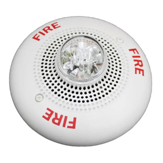
SpectrAlert SP2C Series
Ceiling Mount Speaker/Strobes for
Fire Protective Signaling Systems
For use with the following models: SP2C2415, SP2C241575, SP2C2430,
SP2C2475, SP2C2495, SP2C24115, SP2C24177
U.S. Patent Nos. 5,850,178; 5,598,139; 6,049,446; 6,057,778; D424465; 5,931,569; 6,623,143
Specifications:
Mechanical
Input Terminals:
12 to 18 AWG (3.31 to 0.82 mm
Speaker Size:
4 inches (101 mm)
Overall Dimensions:
6.8˝ diameter (173 mm)
Maximum Supervisory
Voltage (Speaker):
50 VDC
Operational Humidity Range: 10 – 93% RH (non-condensing)
For Strobes
Voltage:
Regulated 24 DC/FWR
Operational Voltage Range: 16–33 Volts
Synchronous Applications
with MDL Module:
17–33 Volts
NOTE: The SP2C Series is suitable for dry and humid environments.
Note for Strobes – Do not exceed: 1) 16-33 Voltage range limit; 2) Maximum number of 70 strobe lights when connecting the MDL
Sync module with a maximum line impedance of 4 Ohms per loop and: 3) Maximum line impedance as required by the fire alarm
control manufacturer.
NOTICE: This manual shall be left with the owner/user of this
equipment.
General Description
The National Fire Protection Association (NFPA) has published
standards and recommended practices for the speaker/strobes
described in this manual. As a result, the installer must be famil-
iar with these requirements as well as all local codes and special
requirements of the authority having jurisdiction.
The SpectrAlert SP2C series ceiling mount speaker/strobe can be
operated with distribution amplifiers having an output voltage of
either 25 volts or 70.7 volts.
The speakers operate at any one of four input power levels. The
output sound level is selected at the time of installation, but can
be changed, if necessary.
The speaker is also equipped with a capacitive input to allow for
DC supervision.
The SpectrAlert SP2C series ceiling mount strobe can be installed
in systems using 24-volt panels having DC or full-wave rectified
(FWR) power supplies. The strobes can also be installed in appli-
cations requiring synchronization (MDL required) or applications
that do not require synchronization (no module required).
The SpectrAlert SP2C series ceiling mount speaker/strobes are
designed to meet the requirements of most agencies governing
these devices, including: NFPA, The National Fire Alarm Code,
UL, CSFM, MEA. Also, check with your local Authority Having
Jurisdiction for other codes or standards that may apply.
D690-02-00
Flash Rate:
2
)
Light Output:
Sound Output:
Listings:
Not suitable for use in air handling spaces.
Power Supply Considerations For Strobes
Panels typically supply DC filtered voltage or FWR (full-
wave rectified) voltage. The system design engineer must cal-
culate the number of units used in a zone based on the
type of panel supply. Be certain the sum of all the device currents
do not exceed the current capability of the panel. Calculations are
based on using the device current found in Table 2 and must be
the current specified for the type of panel power supply used.
Wire Sizes
The designer must be sure that the last device on the circuit has
sufficient voltage to operate the device within its rated voltage.
When calculating the voltage available to the last device, it is
necessary to consider the voltage drop due to the resistance of the
wire. The thicker the wire, the less the voltage drop. Generally, for
purposes of determining the wire size necessary for the system,
it is best to consider all of the devices as "lumped" on the end of
the supply circuit (simulates "worst case").
Typical wire size resistance:
18 AWG solid:
16 AWG solid:
14 AWG solid:
12 AWG solid:
Note: If class "A" wiring is installed, the wire length may be up to
4 times the single wire length in this calculation.
1
firealarmresources.com
3825 Ohio Avenue, St. Charles, Illinois 60174
1-800-SENSOR2, FAX: 630-377-6495
www.systemsensor.com
1 Flash Per Second
Models with 15 only in the model number are
listed at 15 candela.
Models with 1575 in the model number are
listed at 15 candela per UL 1971 but will pro-
vide 75 candela on axis (straight down).
Models with 30, 75, 95, 115, 177 are for that
candela.
Sound
output
levels
are
Underwriters Laboratories in their reverberant
room.
Always use the sound output specified as UL
Reverberant Room when comparing products.
UL S5512 Strobe, UL S4048 (Speaker/Strobe)
Approximately 8 ohms/1,000 ft.
Approximately 5 ohms/1,000 ft.
Approximately 3 ohms/1,000 ft.
Approximately 2 ohms/1,000 ft.
established
at
I56-1455-009R
Advertisement
Table of Contents

Related Manuals for System Sensor SpectrAlert SP2C Series


Summary of Contents for System Sensor SpectrAlert SP2C Series
- Page 1 The speaker is also equipped with a capacitive input to allow for the supply circuit (simulates “worst case”). DC supervision. Typical wire size resistance: The SpectrAlert SP2C series ceiling mount strobe can be installed 18 AWG solid: Approximately 8 ohms/1,000 ft. in systems using 24-volt panels having DC or full-wave rectified 16 AWG solid: Approximately 5 ohms/1,000 ft.
- Page 2 Electrical Example: Assume you have 10 devices on a zone and each requires 50 mA average and 2000 Ft. of 14 AWG wiring 1. Connect the speaker/strobe as shown in Figure 1. Keep in mind (total length=outgoing+return). The voltage at the end that even though the speaker and strobe are a single mechani- of the loop is 0.050 amps per device×10 devices×3 ohms cal unit, they are electrically independent and require separate...
- Page 3 Figure 4: Positioning for maximum brightness 2. See Figure 2 as an example of how to select a Watt input when a 25 volt amplifier is being used. Notice that NOTE: For maximum brightness, unit must be mounted with the header, SW1, has two shunts. One shunt is used to flash angles as shown.
- Page 4 Three-Year Limited Warranty System Sensor warrants its enclosed speaker to be free from defects in #__________, 3825 Ohio Avenue, St. Charles, IL 60174. Please include materials and workmanship under normal use and service for a period a note describing the malfunction and suspected cause of failure.
Need help?
Do you have a question about the SpectrAlert SP2C Series and is the answer not in the manual?
Questions and answers