Advertisement
Quick Links
INSTALLATION AND MAINTENANCE INSTRUCTIONS
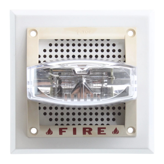
SP100 Series Dual Transformer
Speakers and Speaker/Strobes for
Fire Protective Signaling Systems
Specifications
Mechanical
Input Terminals:
Speaker Size:
Grille Size
Round:
Square:
Electrical
Voltage Input:
Frequency Range:
Operating Temperature Range:
NOTICE: This manual should be left with the owner/user
of this equipment.
General Description
The National Fire Protection Association (NFPA) has pub-
lished standards and recommended practices for the speak-
ers described in this manual. As a result, the installer must
be familiar with these requirements as well as all local
codes and special requirements of the authority having ju-
risdiction.
SP100 series speakers can be operated with distribution
amplifiers having an output voltage of either 25 volts or
70.7 volts.
The speakers operate at any one of six input power levels.
The output sound level is selected at the time of installa-
tion, but can be changed, if necessary.
The speaker is also equipped with a capacitive input to al-
low for DC supervision.
An optional, attached 1.5 or 15 candela (cd) strobe is also
available from System Sensor for use with the speaker. Al-
though they are shipped as a unit, the strobe and speaker
are electrically independent and require separate power
sources. Strobes can be powered by means of a full-wave
rectified unfiltered supply.
D400-40-00
Technical Manuals Online! - http://www.tech-man.com
12 to 18 AWG (3.31 to 0.82 mm
4 inches (101 mm)
7-3/8" (187 mm)
5" (127 mm)
25 volts or 70.7 volts (nominal)
400 - 4000 Hz
32° to 120° F (0° to 49° C)
Installation
All wiring must be installed in compliance with the Na-
tional Electrical Code and all applicable local codes as well
as any special requirements of the authority having juris-
diction, using the proper wire size. This also includes all
applicable NFPA Standards, ANSI/UL 1480, and NEC 760.
Electrical
1. Connect the speaker and strobe (if used) as shown in
NOTE: Do NOT loop electrical wiring under terminal
2. Notice that the speaker circuit board is equipped with
Figure 1. Electrical connections:
1
3825 Ohio Avenue, St. Charles, Illinois 60174
2
)
Figure 1. Keep in mind that even though the speaker and
optional strobe are a single mechanical unit, they are
electrically independent and require separate power
sources.
screws. Wires connecting the device to the control
panel must be broken at the device terminal con-
nection in order to maintain electrical supervision.
two sets of posts and associated electrical jumper wires.
One set of posts is numbered 1 through 6 while the other
is labeled A and B. Both electrical leads are fitted with a
barrel connector. These two sets of posts and leads en-
able the installer to select any one of six sound pressure
levels with either a 25 volt or 70.7 volt amplifier.
A Division of Pittway
1-800-SENSOR2, FAX: 630-377-6495
I56-609-03
Advertisement

Subscribe to Our Youtube Channel
Related Manuals for System Sensor SP100 Series


Summary of Contents for System Sensor SP100 Series
- Page 1 An optional, attached 1.5 or 15 candela (cd) strobe is also able the installer to select any one of six sound pressure available from System Sensor for use with the speaker. Al- levels with either a 25 volt or 70.7 volt amplifier.
- Page 2 For example, Table 1 shows that to select a 1/4 Watt in- Table 1: put when a 25 volt amplifier is being used, slide the blue lead onto post 3 and slide the yellow lead onto post B. Similarly, to select a 4 Watt input with a 70.7 volt ampli- 1/2 W 1/4 W 1/8 W...
- Page 3 Under no circumstances can the strobe input voltage ex- Strobe Light Ratings The signaling strobe is rated for 0° to 49° C and is not suit- ceed 33 VDC or be less than 18 VDC. able for outdoor use. To calculate battery requirements, use the current values See Figure 3.
- Page 4 System Sensor makes no other The Company shall not be obligated to repair or replace units which are express warranty for this speaker/strobe.
- Page 5 INSTALLATION AND MAINTENANCE INSTRUCTIONS SP100ADA Series Dual-transformer Speaker/Strobes for Fire Protective A Division of Pittway 3825 Ohio Avenue, St. Charles, Illinois 60174 Signaling Systems 1-800-SENSOR2, FAX: 630-377-6495 Specifications Mechanical Input Terminals: 12 to 18 AWG (3.31 to 0.82 mm Speaker Size: 4 inches (101 mm) Grille Size: 5"...
- Page 6 For example, Table 1 shows that to select a 1/4 Watt in- Table 1: put when a 25 volt amplifier is being used, slide the blue 1/2 W 1/4 W 1/8 W lead onto post 3 and slide the yellow lead onto post B. Similarly, to select a 4 Watt input with a 70.7 volt ampli- 25 V fier, slide the blue and yellow leads onto posts 2 and A,...
- Page 7 NOTE: The light output at 0° viewing angle for Strobe Light Ratings The signaling strobe is rated for 0° to 49° C and is not suit- SP1*241575ADA is 75 cd (See Figure 3). able for outdoor use. R = Red The rated light output of the SP1 2415ADA and W = White...
- Page 8 System Sensor makes no other The Company shall not be obligated to repair or replace units which are express warranty for this speaker/strobe.
- Page 9 System Sensor recommends that the installer become fa- authority having jurisdiction, using the proper wire size. miliar with these standards and practices, local codes, and 1.
- Page 10 propriate power post. When connecting this plug, make Figure 1. Wiring diagram shown in alarm condition: sure the black wire is connected to the COM post and the red wire to the numbered post. NOTE: The plug MUST be installed for the speaker to oper- 1/4W ate.
- Page 11 C.1 before wiring the speaker/ strobe assembly as described in paragraph B.2. Figure 5. Speaker, Strobe Semiflush Mount: D. Flush Mount Flush mounting requires the use of a System Sensor BBD deep box, or equivalent. 1. Speaker Only (Figure 6) MP-SF...
-
Page 12: Ceiling Mount
The visual warning signal is suitable for direct Three-Year Limited Warranty System Sensor warrants its enclosed sounder to be free from defects in ment, RA #__________, 3825 Ohio Avenue, St. Charles, IL 60174. Please materials and workmanship under normal use and service for a period of include a note describing the malfunction and suspected cause of failure. - Page 13 INSTALLATION AND MAINTENANCE INSTRUCTIONS V4R24ADA Series Speaker/Strobes A Division of Pittway 3825 Ohio Avenue, St. Charles, Illinois 60174 for Fire Protective Signaling Systems 1-800-SENSOR2, FAX: 630-377-6495 Specifications Speaker Frequency Range: 400 Hz to 4000Hz Supervision: Capacitive input for supervisory DC voltage Mounting: Standard 4"...
- Page 14 Figure 1. Vertical and horizontal light distribution: Degrees % of Rating 0˚ 5 - 25 30 - 45 45˚ –45˚ LIGHT 90˚ –90˚ The light output rating of the Model V4R24110ADA is 110 2. See Figure 2. The speaker is equipped with five posts cd;...
- Page 15 C. Semiflush Wall Mount Figure 2: (a) System Sensor semiflush mounting plates are shipped with #8 nuts already installed from the 1/4W back. 1/2W (b) Attach the semiflush mounting plate to a standard 4- inch square electrical box using the two 8-32 X 5/8"...
- Page 16 System Sensor makes no other The Company shall not be obligated to repair or replace units which are express warranty for this speaker/strobe.
Need help?
Do you have a question about the SP100 Series and is the answer not in the manual?
Questions and answers