Table of Contents
Advertisement
Quick Links
Installation AND MAINTENANCE INSTRUCTIONS
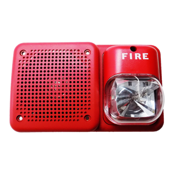
SpectrAlert SP2 Series
Wall Speaker/Strobes for
Fire Protective Signaling Systems
For use with the following models: SP2R2415, SP2R2430, SP2R241575, SP2R2475, SP2R24110,
SP2W2415, SP2W2430, SP2W241575, SP2W2475, SP2W24110
U.S. Patent Nos. 5,593,569; 5.914,665; 5,850,178; 5,598,139; 6,049,446; 6,127,935
Specifications: Speaker
Mechanical
Input Terminals:
12 to 18 AWG (3.31 to 0.82 mm
Speaker Size:
4 inches (101 mm)
Overall Dimensions: 8.25" x 4.9"
Voltage Input:
25 volts or 70.7 volts (nominal)
Frequency Range:
400 – 4000 Hz
Power:
1
⁄
,
4
Operating
Temperature Range: 32° to 120°F (0° to 49°C)
Listings:
UL
Note: As tested by UL (reference revised 1971 STD, sections/paragraphs 27A.1-27A.5 and 48.4), the maximum number
of synchronous strobe lights that can be connected to the MDL synch module is 70. The maximum impedance between
the adjacent units is 250 ohms.
NOTICE: This manual shall be left with the owner/user of
this equipment.
General Description
The National Fire Protection Association (NFPA) has pub-
lished standards and recommended practices for the speak-
er/strobes described in this manual. As a result, the
installer must be familiar with these requirements as well
as all local codes and special requirements of the authority
having jurisdiction.
The SpectrAlert SP2 series speakers can be operated with
distribution amplifiers having an output voltage of either
25 volts or 70.7 volts.
The speakers operate at any one of four input power levels.
The output sound level is selected at the time of installa-
tion, but can be changed, if necessary.
The speaker is also equipped with a capacitive input to
allow for DC supervision.
The SpectrAlert SP2 series strobe can be installed in systems
using 24-volt panels having DC or full-wave rectified (FWR)
power supplies. The strobes can also be installed in appli-
cations requiring synchronization (MDL required) or appli-
cations that do not require synchronization (no module
required).
The SpectrAlert SP2 series speaker/strobes are designed to
meet the requirements of most agencies governing these
devices, including: NFPA, ADA, The National Fire Alarm
Code, UL, CSFM, MEA. Also, check with your local
Authority Having Jurisdiction for other codes or standards
that may apply.
Power Supply Considerations For Strobes
Panels typically supply DC filtered voltage or FWR (full-
wave rectified) voltage. The system design engineer must
D690-01-00
1
⁄
, 1 and 2 Watts
2
Specifications: Strobe
Voltage Range: DC or Full-Wave Rectified
2
)
Flash Rate:
Light Output:
calculate the number of units used in a zone based on the
type of panel supply. Be certain the sum of all the device
currents do not exceed the current capability of the panel.
Calculations are based on using the device current found in
Table 2 and must be the current specified for the type of
panel power supply used.
Wire Sizes
The designer must be sure that the last device on the cir-
cuit has sufficient voltage to operate the device within its
rated voltage. When calculating the voltage available to
the last device, it is necessary to consider the voltage drop
due to the resistance of the wire. The thicker the wire, the
less the voltage drop. Generally, for purposes of determin-
ing the wire size necessary for the system, it is best to con-
sider all of the devices as "lumped" on the end of the sup-
ply circuit (simulates "worst case").
Typical wire size resistance:
18 AWG solid: Approximately 8 ohms/1,000 ft.
16 AWG solid: Approximately 5 ohms/1,000 ft.
14 AWG solid: Approximately 3 ohms/1,000 ft.
12 AWG solid: Approximately 2 ohms/1,000 ft.
Example: Assume you have 10 devices on a zone and each
requires 50 mA average and 2000 Ft. of 14 AWG wiring
(total length=outgoing +return). The voltage at the end
of the loop is 0.050 amps per device × 10 devices × 3
ohms/1,000 ft. x 2000 ft =3 volts drop.
The same number of devices using 12 AWG wire will pro-
duce only 2 volts drop. The same devices using 18 AWG
wire will produce 8 volts drop. Consult your panel manu-
facturer's specifications, as well as SpectrAlert's operating
voltage range to determine acceptable voltage drop.
Note: If class "A" wiring is installed, the wire length may
be up to 4 times the single wire length in this calculation.
1
3825 Ohio Avenue, St. Charles, Illinois 60174
1-800-SENSOR2, FAX: 630-377-6495
www.systemsensor.com
20 to 30 volts, (21 to 30 with MDL module)
1 flash per second
Models with 1575 are listed at 15 candela
per UL1971 but will provide 75 candela on
axis (straight ahead).
Models with 15, 30, 75 or 110 are rated for
that candela.
A Division of Pittway
I56-1368-003R
Advertisement
Table of Contents

Related Manuals for System Sensor SpectrAlert SP2 Series


Summary of Contents for System Sensor SpectrAlert SP2 Series
- Page 1 18 AWG solid: Approximately 8 ohms/1,000 ft. 16 AWG solid: Approximately 5 ohms/1,000 ft. The SpectrAlert SP2 series strobe can be installed in systems 14 AWG solid: Approximately 3 ohms/1,000 ft. using 24-volt panels having DC or full-wave rectified (FWR) 12 AWG solid: Approximately 2 ohms/1,000 ft.
- Page 2 Installation Figure 2. Voltage and Power Selection: All wiring must be installed in compliance with the CORRECT National Electrical Code (NEC) and applicable local codes INCORRECT as well as special requirements of the authority having 25.0V jurisdiction, using the proper wire size. This also includes 25.0V 70.7V all applicable NFPA Standards, ANSI/UL 1480, UL 1971 and...
- Page 3 Mounting Figure 3: Reversible strobe module Reversible strobe module INSERT SCREWDRIVER TO REMOVE Should the back box be located near an obstruction such as a doorway, the strobe module is field-reversible (Fig. 3). To reverse the strobe module: insert screwdriver, as shown in Fig.
- Page 4 The strobe must have an unin- alert persons from hearing the alarm. The speaker may not be heard by terrupted source of power in order to operate correctly. System Sensor rec- persons who are hearing impaired.
Need help?
Do you have a question about the SpectrAlert SP2 Series and is the answer not in the manual?
Questions and answers