Table of Contents
Advertisement
Quick Links
INSTALLATION AND MAINTENANCE INSTRUCTIONS
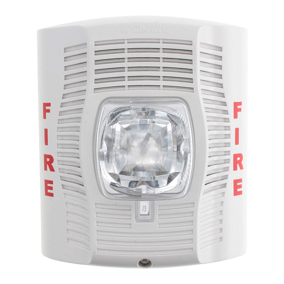
SpectrAlert Advance SPS and SPSV Series
Wall and Ceiling Speaker/Strobes for
Fire Protective Signaling Systems
For use with models: SPSR, SPSRH, SPSW, SPSWH, SPSRV, SPSWV, SPSRK, SPSWK, SPSCR, SPSCRH,
SPSCW, SPSCWH, SPSCRV, SPSCRVH, SPSCWV, SPSCWVH, SPSCWK, SPSCWHK, SPSR-P, SPSRH-P, SPSW-P,
SPSWH-P, SPSRV-P, SPSWV-P, SPSCW-P, SPSCWH-P, SPSCWVH-P, and SPSCHWV-P
PRODUCT SPECIFICATIONS
Operating Temperature
Humidity Range
Nominal Voltage (speakers)
Max. Supervisory Voltage (speakers and strobes) 50 VDC
Strobe Flash Rate
Nominal Voltage (strobes)
Speaker Frequency Range
Power Settings (Speakers)
Operating Voltage Range
(includes fire alarm panels with built in sync)
Operating Voltage with MDL Sync Module
Input Terminal Wire Guage
Dimensions for Speaker/Strobes and Accessories
Wall Product
Length Width
SPS Speaker/Strobe
6.0˝
SPSV Speaker/Strobe
6.0˝
Weatherproof back box **
6.5˝
Surface Mount Skirt
6.5˝
Mounting Box Options
2-Wire Indoor Products
PWBB - red wall plastic weatherproof back box
4 × 4 × 2
1
/
or deeper
8
PWBBW - white wall plastic weatherproof back box
PWBBCW - white ceiling plastic weatherproof back box
The indoor SP and SPV Series are suitable for dry and damp environments. The "K" Series models are suitable for use in both indoor and outdoor applications.
NOTICE: This manual shall be left with the owner/user of this equipment.
The "K" models are suitable for outdoor use in wet environments with out-
door back box supplied with the product.
GENERAL DESCRIPTION
The SpectrAlert Advance series of notification appliances offers a wide range
of speaker/strobe products for wall and ceiling applications, indoors and out-
doors. The strobe portion is designed to be used in 12 or 24 volt, DC or FWR
(full wave rectified) systems. The speaker portion can be operated with distri-
bution amplifiers having an output voltage of either 25 or 70.7 volts.
With its low total harmonic distortion, the SpectrAlert Advance SP series of-
fers high fidelity sound output. The SpectrAlert Advance SPV series offers
greater sound output at every tap setting for applications with high ambient
noise levels. The speakers operate at any one of four input power levels. These
products are electrically backward compatible with the previous generation of
SpectrAlert notification appliances. All SpectrAlert Advance products are suit-
able for use in synchronized systems. The System Sensor MDL module may
be used to provide synchronization for the strobes. Wall and ceiling products
may be used interchangeably (wall products may be used on the ceiling and
ceiling products may be used on the wall.) K Series products are designed to
be used over a wider range of temperatures and are suitable for use in wet
locations.
SS-140-001
Standard 32°F to 120°F (0°C to 49°C)
Standard 10% to 93% Non-condensing K Series Meets NEMA 4X requirements
25 Volts or 70.7 Volts (nominal)
1 flash per second
Regulated 12VDC or FWR or regulated 24DC or FWR
400 to 4000 Hz
1
/
,
1
/
, 1, 2 watts
4
2
8 to 17.5V (12V nominal) or 16 to 33V (24V nominal)
9 to 17.5V (12V nominal) or 17 to 33V (24V nominal)
12-18 AWG
Depth
5.0˝
4.7˝ (including lens and speaker) SPSC Speaker/Strobe
5.0˝
4.8˝ (including lens and speaker) SPSCV Speaker/Strobe
5.5˝
2.9˝*
5.0˝
2.7˝*
*Depth above finished surface of wall or ceiling. **Weatherproff back box dimensions do not include the two mounting tabs.
K Series –40°F to 151°F (–40°C to 66°C)
NOTE: V suffix denotes high volume device, C suffix denotes ceiling device.
Ceiling Product
Weatherproof back box **
Surface Mount Skirt
K Series Products
Plastic
FIRE ALARM SySTEM CONSIDERATIONS
All wiring must be installed in compliance with the National Electrical Code
(NEC) and applicable local codes. System Sensor recommends installing fire
alarm speakers in compliance with NFPA 72, ANSI/UL1480 and NEC 760.
LOOP DESIGN AND WIRING
The system designer must make sure that the total current drawn by the de-
vices on the loop does not exceed the current capability of the panel supply,
and that the last device on the circuit is operated within its rated voltage.
The current draw information for making these calculations can be found in
the tables within this manual. For convenience and accuracy, use the voltage
drop calculator on the System Sensor website (www.systemsensor.com) or
CD-ROM.
When calculating the voltage available to the last device, it is necessary to
consider the voltage drop due to the resistance of the wire. The thicker the
wire, the smaller the voltage drop. Wire resistance tables can be obtained
from electrical handbooks. Note that if Class A wiring is installed, the wire
length may be up to twice as long as it would be for circuits that are not fault
tolerant.
NOTE: For 24 volt applications, the total number of strobes on a single NAC
must not exceed 40, with a maximum loop resistance of 120 ohms. For 12 volt
applications, the total number of strobes must not exceed 12, with a maxi-
mum loop resistance of 30 ohms.
NOTE: Supply power for strobe must be continuous for proper operation.
1
3825 Ohio Avenue, St. Charles, Illinois 60174
1-800-SENSOR2, FAX: 630-377-6495
www.systemsensor.com
Diameter
Depth
6.8˝
4.7˝ (including lens and speaker)
6.8˝
4.8˝ (including lens and speaker)
7.2˝
2.9˝*
7.2˝
2.7˝*
I56-3109-001R
Advertisement
Table of Contents

Related Manuals for System Sensor SPS Series


Summary of Contents for System Sensor SPS Series
- Page 1 SpectrAlert notification appliances. All SpectrAlert Advance products are suit- wire, the smaller the voltage drop. Wire resistance tables can be obtained able for use in synchronized systems. The System Sensor MDL module may from electrical handbooks. Note that if Class A wiring is installed, the wire be used to provide synchronization for the strobes.
- Page 2 FIGURE 1. WIRING DIAGRAM: TAbLE 1. SOUND LEVELS FOR EACh TRANSFORMER POWER TAP: UL Reverberant (dBA @ 10 ft.) SPS, SPSC SPSV, SPSCV (–) (–) OUTPUT TO INPUT FROM NEXT SPEAKER AMPLIFIER OR EOL (–) (–) OUTPUT TO INPUT FROM CAUTION NEXT STROBE POWER...
- Page 3 Connect field wiring to terminals, as shown in Figure 1. FIGURE 8: CEILING MOUNT PRODUCT WITh bACk bOx SkIRT: If the product is not to be installed at this point, use the paint cover to prevent contamination of the mounting plate. To attach product to mounting plate, remove the paint cover, then hook tabs on the product housing into the grooves on mounting plate.
- Page 4 The speaker may not be heard by persons who are hearing impaired. to operate correctly. System Sensor recommends that the horn and signal strobe always be used in combination so that the risks from any of the above limitations are minimized.
Need help?
Do you have a question about the SPS Series and is the answer not in the manual?
Questions and answers