Advertisement
Quick Links
INSTALLATION AND MAINTENANCE INSTRUCTIONS
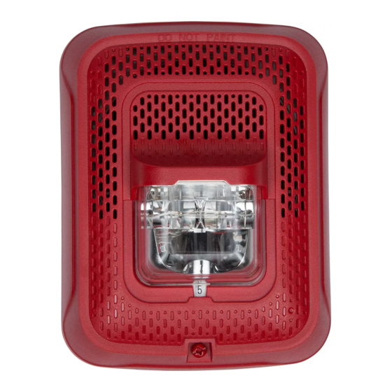
Selectable Output Speaker Strobes
– Wall and Ceiling Mount
For use with the following models:
Wall Speakers: SPSRL, SPSWL, SPSRL-P, SPSWL-P, SPSRL-SP, SPSWL-CLR-ALERT
Ceiling Speakers: SPSCRL, SPSCWL, SPSCWL-P, SPSCWL-SP, SPSCWL-CLR-ALERT
PRODUCT SPECIFICATIONS
Standard Operating Temperature:
Humidity Range:
Nominal Voltage (speakers):
Maximum Supervisory Voltage:
Speaker Frequency Range:
Power Settings:
Input terminal wire gauge:
Strobe Flash Rate:
Nominal Voltage (strobes):
Operating Voltage Range (includes fire alarm
panels with built in sync):
Operating Voltage with MDL3 Sync Module:
DIMENSIONS FOR PRODUCTS AND ACCESSORIES
WALL PRODUCTS
Wall Speaker Strobe
CEILING PRODUCTS
Ceiling Speaker Strobe
WALL SURFACE MOUNT BACK BOX
Speaker Strobe with SBBSPRL/WL Surface
Mount Back Box
CEILING SURFACE MOUNT BACK BOX
Speaker Strobe with SBBCRL/WL Surface
Mount Back Box
NOTICE: This manual shall be left with the owner/user of this equipment.
BEFORE INSTALLING
Please read the System Sensor Voice Evacuation Application Guide, which
provides detailed information on speaker notification devices, wiring and
special applications. Copies of this manual are available from System Sensor.
NFPA 72 and NEMA guidelines should be observed. System Sensor also rec-
ommends installing fire alarm speakers in compliance with NFPA 72, ANSI/
UL 1480 and NEC 760
Important: The notification appliance used must be tested and maintained
following NFPA 72 requirements.
GENERAL DESCRIPTION
System Sensor series of notification appliances offer a wide range of audible
and visible devices for life safety notification. Our indoor speaker strobes
come with 7 field selectable candela setting. The strobe portion is designed
to be used in 12 VDC, 24VDC, or 24V FWR (full wave rectified) systems. The
speaker is designed to be used at either 25 or 70.7 volts, and operate at any
one of four input power levels. Our speaker strobes are suitable for dry and
damp environments. These products are electrically backwards compatible
with previous generation of System Sensor speaker strobes. With its low total
harmonic distortion, the System Sensor SPL series offers high fidelity sound
output.
Speakers Strobes are public mode notification appliances intended to alert oc-
cupants of a life safety event. The speaker is listed to ANSI/UL 1480 (public
mode) and the strobe is listed to ANSI UL 1638 (public mode).
32°F to 120°F (0°C to 49°C)
10 to 93% Non-condensing
25 Volts or 70.7 Volts
50 VDC
400 – 4000 Hz
¼, ½, 1, 2 Watts
12 to 18 AWG
1 flash per second
Regulated 12VDC, regulated 24VDC or FWR
8 to 17.5V (12V nominal) or 16 to 33V (24V nominal)
8.5 to 17.5V (12V nominal) or 16.5 to 33V (24V nominal)
Length
Width
6.5" (165 mm)
5.00" (127 mm)
Length
Width
6.8" (173 mm)
N/A
Length
Width
6.62" (168mm)
5.12" (130 mm)
Diameter
6.92" (176 mm)
FIRE ALARM SYSTEM CONSIDERATIONS
System Sensor also recommends installing fire alarm speakers in compliance
with NFPA 72, ANSI/UL 1480 and NEC 760.
SYSTEM DESIGN
The system designer must make sure that the total current drawn by the de-
vices on the loop does not exceed the current capability of the panel supply,
and that the last device on the circuit is operated within its rated voltage. The
current draw information for making these calculations can be found in the
tables within this manual. For convenience and accuracy, use the voltage drop
calculator on the System Sensor website (www.systemsensor.com).
When calculating the voltage for the last device, it is necessary to consider
the voltage drop due to the resistance of the wire. The thicker the wire, the
smaller the voltage drop. Note that if Class A wiring is installed, the wire
length may be up to twice as long as it would be circuits that are not fault
tolerant. The total number of strobes on a single NAC must not exceed 69 for
24 volt applications.
AVAILABLE CANDELA SETTINGS
System Sensor offers a wide range of candela settings for your life safety
needs. In order to select your candela output, adjust the slide switch on the
rear of the product to the desired candela setting on the selector switch. (See
Figure 1.)
The candela setting can also be verified by looking into the small window
on the front of the unit. See Tables 1 and 2 for candela settings for wall and
ceiling products. All products meet the light output profiles specified in the
appropriate UL Standards. (See Figures 2–4.)
1
3825 Ohio Avenue, St. Charles, Illinois 60174
MOUNTING BOX OPTIONS
Depth
SBBSPRL/WL (wall), SBBCRL/WL (ceil-
2.30" (58.4 mm)
ing), 4" x 4" x 2
Depth
using 12AWG, 14 AWG, or adding extra
2.87" (73mm)
wires in the box, a deeper box or exten-
sion ring is recommended.)
Depth
2.30" (58.4 mm)
Depth
5.37" (116mm)
800/736-7672, FAX: 630/377-6495
www.systemsensor.com
SPEAKER STROBES
/
"or deeper (When
1
8
I56-0002-002
12/10/2018
Advertisement

Subscribe to Our Youtube Channel
Related Manuals for System Sensor SPSRL


Summary of Contents for System Sensor SPSRL
- Page 1 AVAILABLE CANDELA SETTINGS with previous generation of System Sensor speaker strobes. With its low total System Sensor offers a wide range of candela settings for your life safety harmonic distortion, the System Sensor SPL series offers high fidelity sound needs. In order to select your candela output, adjust the slide switch on the output.
- Page 2 FIGURE 1. CANDELA SELECTOR FIGURE 4. LIGHT OUTPUT - VERTICAL DISPERSION, CEILING TO WALLS TO FLOOR Percent of Degrees* Rating 5-25 A0486-00 30-45 CURRENT DRAW AND AUDIBILITY RATINGS For the strobe, the current draw for each setting is listed in Tables 1 and 2. TABLE 1.
- Page 3 Shorting Spring A0499-02 AVAILABLE POWER SETTINGS System Sensor offers a wide range of power settings for your life safety needs, including ¼, ½, 1, and 2W. A0522-01 Sound levels data per UL 1480 can be found in Table 3. FIGURE 9. CEILING SPEAKER/STROBE TABLE 3.
- Page 4 The speaker may not be heard by persons who are hearing impaired. FCC STATEMENT System Sensor speakers have been tested and found to comply with the limits for a radio frequency energy and, if not installed and used in accordance with the instruction Class B digital device, pursuant to part 15 of the FCC Rules.
Need help?
Do you have a question about the SPSRL and is the answer not in the manual?
Questions and answers