
Subscribe to Our Youtube Channel
Related Manuals for Panduit Atlona AT-UHD-SW-5000ED


Summary of Contents for Panduit Atlona AT-UHD-SW-5000ED
- Page 1 4K / UHD Five-Input HDMI Switcher with Two HDBaseT Inputs and Mirrored HDMI / HDBaseT Outputs Atlona Manuals AT-UHD-SW-5000ED Switchers...
- Page 2 Version Information Version Release Date Notes Dec 2020 New format Sep 2021 IR remote no longer shipping with unit; IR documentation is still included for units in the field. AT-UHD-SW-5000ED...
- Page 3 Welcome to Atlona! Thank you for purchasing this Atlona product. We hope you enjoy it and will take a extra few moments to register your new purchase. Registration only takes a few minutes and protects this product against theft or loss. In addition, you will receive notifications of product updates and firmware.
- Page 4 Atlona, Inc. (“Atlona”) Limited Product Warranty Coverage Atlona warrants its products will substantially perform to their published specifications and will be free from defects in materials and workmanship under normal use, conditions and service. Under its Limited Product Warranty, Atlona, at its sole discretion, will either: •...
- Page 5 Atlona, Inc. (“Atlona”) Limited Product Warranty • Damage, deterioration or malfunction resulting from the installation or removal of this product from any installation, any unauthorized tampering with this product, any repairs attempted by anyone unauthorized by Atlona to make such repairs, or any other cause which does not relate directly to a defect in materials and/or workmanship of this product.
- Page 6 Safety and Certification 9. Do not defeat the safety purpose of a polarized CAUTION or grounding-type plug. A polarized plug has two RISK OF ELECTRIC SHOCK blades with one wider than the other. A grounding DO NOT OPEN type plug has two blades and a third grounding CAUTION: TO REDUCT THE RISK OF prong.
-
Page 7: Table Of Contents
Table of Contents Introduction Features Package Contents Panel Description Front Panel Rear Panel Installation Power Audio RS-232 Connection Instructions Connection Diagram IP Configuration Setting the IP Address using the Web Server Auto IP (APIPA) Mode Device Operation LED Indicators System Configuration Getting the MAC Address Changing the Network IP Mode Setting Static IP Mode using the Front Panel... - Page 8 Table of Contents Appendix Updating the Firmware Using the Web Server Using the USB Interface HDBaseT Testing Mounting Instructions Single Unit Rack Installation Dual Unit Rack Installation Flat Surface IR Remote Control Specifications AT-UHD-SW-5000ED...
-
Page 9: Introduction
Introduction The Atlona AT-UHD-SW-5000ED is a 5x1 switcher with two HDBaseT inputs, three HDMI inputs, mirrored HDMI ™ and HDBaseT outputs, balanced audio outputs, automatic input selection, and advanced display control capability. The HDBaseT inputs match perfectly with the HDVS-200-TX modules to enable VGA and HDMI sources to be easily integrated into a system. -
Page 10: Panel Description
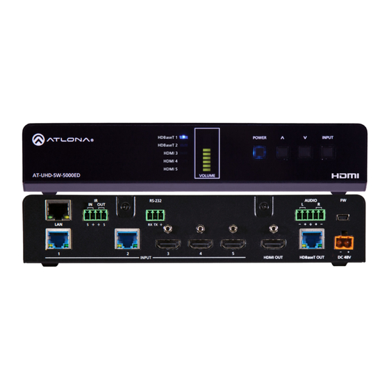
Panel Description Front Panel HDBaseT 1 INPUT POWER HDBaseT 2 HDMI 3 HDMI 4 HDMI 5 AT-UHD-SW-5000ED VOLUME Input LED Indicators Cursor Buttons RS-232 AUDIO These LED indicators display which input is routed Press and release these buttons to increase or to the HDMI OUT port. -
Page 11: Rear Panel
HDBaseT 1 POWER INPUT HDBaseT 2 HDMI 3 HDMI 4 Panel Description HDMI 5 AT-UHD-SW-5000ED VOLUME Rear Panel AUDIO RS-232 RX TX INPUT HDMI OUT HDBaseT OUT DC 48V AUDIO Connect an Ethernet cable from this port to the Local Connect an audio output device to this port using the Area Network (LAN). -
Page 12: Installation
Installation HDBaseT 1 POWER INPUT HDBaseT 2 HDMI 3 HDMI 4 Power HDMI 5 VOLUME Connect the included 2-pin captive screw connector to the DC 48V power receptacle on the rear of the unit. Insert the positive and negative leads, from the power supply, into the terminals of the 2-pin captive screw connector block, as shown. - Page 13 Installation RS-232 The AT-UHD-SW-5000ED provides an RS-232 port which can be used to control a display connected to an HDMI output. Atlona recommends controlling the AT-UHD-SW-5000ED using IP and reserving the RS-232 port for local display control. 1. Use wire strippers to remove a portion of the cable jacket. 2.
-
Page 14: Connection Instructions
Installation Connection Instructions 1. Connect up to two HDBaseT transmitters to INPUT 1 and INPUT 2. Atlona recommends CAT-5e or better cabling. 2. Connect up to five UHD/HD HDMI sources to ports INPUT 3 through INPUT 5. 3. Connect an HDMI cable from the HDMI OUT port to a UHD/HD display. 4. -
Page 15: Connection Diagram
Installation Connection Diagram Ceiling Speakers Laptop HDMI PC AT -HD A IN AT-GAIN-60 AT-HDVS-200-TX 0E D -5 00 -U HD AT-UHD-SW-5000ED Laptop -T X- 10 U VS -2 A T- LI N U SB AT-OME-RX11 AT-HDVS-210U-TX-WP Display AT-UHD-SW-5000ED... -
Page 16: Ip Configuration
Installation IP Configuration The AT-UHD-SW-5000ED is shipped with DHCP enabled. Once connected to a network, the DHCP server (if available), will automatically assign an IP address to the unit. If the AT-UHD-SW-5000ED is unable to detect a DHCP server within 15 seconds, then the unit will use a self-assigned IP address within the range of 169.254.xxx.xxx. Use an IP scanner, along with the MAC address on the bottom of the unit, to identify the unit on the network. -
Page 17: Device Operation
Device Operation LED Indicators The LED indicators on both the front and rear of the unit provide basic information on the current status of the AT- UHD-SW-5000ED. Description HDBaseT 1, Solid green The input is the currently selected (active) input. HDBaseT 2, HDMI 3 - The input is not the active input. -
Page 18: System Configuration
Device Operation System Configuration The AT-UHD-SW-5000ED provides easy access to system configuration through the built-in web server, and is the recommended method to adjust network settings. NOTE: When a setting within the Network Settings page is being modified, the background color will switch from white to gray. -
Page 19: Changing The Network Ip Mode
Device Operation Changing the Network IP Mode By default, the AT-UHD-SW-5000ED is set to DHCP mode. Once connected to a network, and if a DHCP server is found (or available), the AT-UHD-SW-5000ED will be assigned an IP address on the network, and no further network configuration is required. -
Page 20: Setting Static Ip Mode Using The Front Panel
Device Operation Setting Static IP Mode using the Front Panel By default, the AT-UHD-SW-5000ED is set to DHCP mode. Once connected to a network, and if a DHCP server is found (or available), the AT-UHD-SW-5000ED will be assigned an IP address on the network, and no further network configuration is required. -
Page 21: Changing The Telnet Port
Device Operation Changing the Telnet Port Typically, the Telnet service is assigned to TCP port 23. This is the default setting for the AT-UHD-SW-5000ED. However, depending upon the network environment, the default Telnet port can be changed. 1. Login to the web server. Refer to Introduction to the Web Server (page 38). -
Page 22: Telnet Login Mode
Device Operation Telnet Login Mode When a Telnet session is requested, the AT-UHD-SW-5000ED provides the option to prompt for user credentials or bypass authentication before the Telnet session begins. Prompting for credentials can be enabled or disabled. When prompting for user credentials, use the same login information required by the built-in web server. 1. -
Page 23: Setting The Host Name
Device Operation Setting the Host Name By default, the AT-UHD-SW-5000ED is assgned a hostname, which is constructed as follows: SW52ED-[last six digits of MAC address] For example, a default hostname might look like this: SW52ED-006154. This value can be changed to easily identify the AT-UHD-SW-5000ED within the Atlona Management System (AMS) or a network. -
Page 24: Video Switching
Device Operation Video Switching Enabling / Disabling Auto-Switching The AT-UHD-SW-5000ED provides auto-switching capability, which is enabled by default. This feature will automatically switch the input to the most recently-connected source. If a source is disconnected, then the input will automatically be switched to the previously-connected source. By default, auto-switching is enabled on the AT-UHD-SW-5000ED, allowing the unit to automatically switch between inputs when sources are connected or disconnected. -
Page 25: Selecting The Input
Device Operation Selecting the Input The active input can be selected from the front panel, the built-in web server, or an API call. Refer to the AT-UHD- SW-5000ED Application Programming Interface for more information. 1. Login to the web server. Refer to Introduction to the Web Server (page 38). -
Page 26: Resetting To Factory-Defaults
Device Operation Resetting to Factory-Defaults The following procedure will reset the AT-UHD-SW-5000ED to factory-default settings. The network IP mode will be set to DHCP mode. Using the Web Server 1. Login to the web server. Refer to Introduction to the Web Server (page 38). -
Page 27: Using The Front Panel
Device Operation Using the Front Panel 1. Verify that the AT-UHD-SW-5000ED is powered. 2. Simultaneously press and hold the INPUT and POWER buttons for 15 seconds. 3. The input indicator will switch to HDBaseT 1. HDBaseT 1 INPUT POWER HDBaseT 2 HDMI 3 HDMI 4 HDMI 5... -
Page 28: Audio Management
Device Operation Audio Management The AT-UHD-SW-5000ED provides volume control and independent audio muting. Audio muting can be controlled on HDMI OUT, HDBaseT OUT, and ANALOG OUT ports. To de-embed the source audio on the ANALOG OUT port, connect the included 5-pin captive screw connector to the ANALOG OUT port. De-embedding audio is restricted to multichannel Linear PCM formats. -
Page 29: Audio Output Muting
Device Operation Audio Output Muting 1. Login to the web server. Refer to Introduction to the Web Server (page 38). The default username and password are listed below: Username: root Password: Atlona 2. Click Settings in the menu bar. 3. Locate the Audio Settings section. 4. -
Page 30: User Management
Device Operation User Management The AT-UHD-SW-5000ED allows the administrator password to be changed. The password applies to both the web server and Telnet sessions. Note that the Username field cannot be changed. All users have the same level of access to control the AT-UHD-SW-5000ED. However, only the root user is allowed to manage other users. Up to three additional users can be created. -
Page 31: Adding Users
Device Operation Adding Users 1. Login to the web server. Refer to Introduction to the Web Server (page 38). The default username and password are listed below: Username: root Password: Atlona 2. Click Config in the menu bar. 3. Enter the desired username and password for the desired user field: User 1, User 2, and User 3. 4. -
Page 32: Editing / Deleting Users
Device Operation Editing / Deleting Users The username and password of a user can be changed using this method. 1. Login to the web server. Refer to Introduction to the Web Server (page 38). The default username and password are listed below: Username: root Password: Atlona 2. -
Page 33: Edid Management
Device Operation EDID Management Before a source can send picture and sound to a display device, the source reads the EDID (Extended Display Identification Data) structure, which is stored in the display. The EDID contains information about what type of video and audio formats are supported by the display. - Page 34 Device Operation 4. Click the drop-down list, next to the port that is connected to the display device, and select the desired EDID preset. For example, if the HDMI IN 3 port is connected to a display, click the Input 3 drop-down list and select the EDID.
-
Page 35: Storing Edid Data
Device Operation Storing EDID Data The AT-UHD-SW-5000ED provides eight memory locations which can be used to store EDID data. Any downstream EDID can be captured and stored in these locations. Each memory location is non-volatile and captured EDID data is stored after power is disconnected from the unit. 1. - Page 36 Device Operation 5. Click the drop-down list, next to the output which will be used to fetch the EDID. In this example, since the display is connected to the HDMI OUT port, a memory location next to the Output 1 option is selected. Here, the EDID will be stored in MEM_1.
-
Page 37: Hdcp Content
Device Operation HDCP Content Normally, if a source is transmitting HDCP content to a display that is not HDCP-compatible, then the resulting image on the display can be “snow”, image flickering, or no picture. For example, in the illustration below, a laptop source is connected to the AT-UHD-SW-5000ED. -
Page 38: Configuration And Management Interfaces
Configuration and Management Interfaces Introduction to the Web Server The AT-UHD-SW-5000ED includes a built-in web server. Atlona recommends that the web server be used to set up AT-UHD-SW-5000ED, as it provides intuitive management of all features. Follow the instructions below to access the webGUI. -
Page 39: Home Page
Configuration and Management Interfaces Home Page After logging in, the Home page will be displayed. The Info page provides various information about the AT-UHD- SW-5000ED, including software version and video information. Model The model SKU of this product. Video Format The input resolution of the source device. -
Page 40: Network Setup Page
Configuration and Management Interfaces Network Setup Page The Network Setup page provides information about the current network settings of the AT-UHD-SW-5000ED. In addition, the network mode, Telnet port, and hostname can be assigned from this page. DHCP Hostname Click the desired setting to switch the AT-UHD-SW- Displays the hostname of the AT-UHD-SW-5000ED, as it 5000ED to ON or OFF mode. -
Page 41: Settings Page
Configuration and Management Interfaces Settings Page The Settings page is divided into three sections: Video, Audio, and HDCP. The Video section provides controls for switching modes and input selection. The Audio section provides options to control the output audio volume and de-embedding. -
Page 42: Config Page
Configuration and Management Interfaces Config Page The Config page provides management of the administrator password. The administrator username (“root”) cannot be changed. Refer to User Management (page 30) for more information. Up to three additional users can be managed within this page. This page also provides settings for both local and HDBaseT RS-232 control. Username (old) This field cannot be changed. - Page 43 Configuration and Management Interfaces System Sets the RS-232 port settings and used for local control by a third-party control system. Output2 If the AT-UHD-SW-5000ED is connected to a device such as the AT-UHD-EX-100CE-RX-PSE, the drop-down list can be set to the baud rate of the HDBaseT RS-232 settings on the corresponding device. If the AT-UHD-SW-5000ED is connected to another HDBaseT device, such as the AT-UHD-CLSO-824, the drop-down list will be disabled and the HDBaseT baud rate will be locked at 115200.
-
Page 44: Edid Page
Configuration and Management Interfaces EDID Page This page provides controls for selecting and storing EDID data. Refer to EDID Management (page 33) for more information. EDID Settings Click these drop-down lists to select the desired EDID to be used for each input. The following EDID presets are available. - Page 45 Configuration and Management Interfaces HDCP Settings Each input provides control of how HDCP content is handled. Some source devices will send HDCP content if an HDCP-compliant display (sink) is detected. However, there may be applications where sending HDCP content is not desired.
-
Page 46: Control Page
Configuration and Management Interfaces Control Page This page provides controls for CEC, device timers, and configuration for controlling external devices. NOTE: To display all settings on the screen, as shown below, the Display Auto Power drop-down list must be set to Enabled. Power Click this drop-down list to select the control protocol for the POWER button on the front panel. - Page 47 Configuration and Management Interfaces Display Mode Click this drop-down list to select the power mode for the source / display. Setting Description DispSW AVon Display switches on/off, source audio/video signal always on. DispSW AVSW Display switches on/off, source audio/video signal switches on/off. AV SW Display is always on, source audio/video signal switches on/off Always ON...
- Page 48 Configuration and Management Interfaces Display Mode Click this drop-down list to select the power mode for the source / display. Setting Description DispSW AVon Display switches on/off, source audio/video signal always on. DispSW AVSW Display switches on/off, source audio/video signal switches on/off. AV SW Display is always on, source audio/video signal switches on/off IP Mode...
-
Page 49: Hdvs Page
Configuration and Management Interfaces HDVS Page This page provides management for HDVS HDBaseT transmitters that may be connected to the AT-UHD-SW- 5000ED. If a transmitter is connected, then the device will be displayed under the associated input. In the example below, an AT-HDVS-210U-TX-WP is connected to INPUT 2 on the AT-UHD-SW-5000ED. -
Page 50: Update Page
Configuration and Management Interfaces Update Page This page provides management for updating the AT-UHD-SW-5000ED firmware. Choose File Click this button to select the firmware file to be uploaded to the AT-UHD-SW-5000ED. Note that this button is available for both the “master” firmware and Valens chip update. Upload Click this button to begin the firmware update process. -
Page 51: Hdbt Page
Configuration and Management Interfaces HDBT Page This page provides management for updating the AT-UHD-SW-5000ED firmware. HDBT Zone Click this drop-down list to select the output channel (ZONE OUT) to test. Refer to HDBaseT Testing (page 55) more information. AT-UHD-SW-5000ED... -
Page 52: Appendix
Appendix Updating the Firmware Updating the firmware can be completed using either the USB interface or the built-in web server. Atlona recommends using the web server for updating the firmware. However, if a network connection is not available, the AT-HDVS-210H-TX-WP firmware can be updated using a USB-A to USB mini-B cable. Using the Web Server Requirements: •... -
Page 53: Using The Usb Interface
Appendix Using the USB Interface Requirements: • AT-UHD-SW-5000ED • Firmware file • Computer with a USB port HDBaseT 1 POWER INPUT • USB-A to USB mini-B cable HDBaseT 2 HDMI 3 HDMI 4 1. Download the firmware file from atlona.com and extract the contents of the .zip file to a folder on the computer HDMI 5 desktop. - Page 54 Appendix 7. Delete all files from the USB UPDATE drive, if any are present. 8. Drag-and-drop the firmware file to the drive. 9. After the file has been copied, disconnect the USB cable from both the computer and the AT-UHD-SW-5000ED. 10.
-
Page 55: Hdbaset Testing
Appendix HDBaseT Testing The web server of the AT-UHD-SW-5000ED provides a tool for testing the signal integrity of HDBaseT cables. This tool is useful for troubleshooting and identifying defective or damaged category cables which are connected from the HDBaseT INPUTS/OUTPUT ports to a receiver/transmitter. 1. -
Page 56: Mounting Instructions
Appendix Mounting Instructions The AT-UHD-SW-5000ED includes two mounting brackets, which can be used to attach the unit to any flat surface. Use the two enclosure screws, on the sides of the unit to attach the mounting brackets. Single Unit Rack Installation 1. -
Page 57: Dual Unit Rack Installation
Appendix Dual Unit Rack Installation 1. Turn both units upside-down on a flat surface, next to each other, as shown. 2. Position the included mounting plate over the pre-drilled holes on the bottom of the enclosure. When attaching the mounting plate, the countersink bevels on the mounting plate should face upward. Countersink bevel F I E P L I... -
Page 58: Flat Surface
Appendix Flat Surface 1. Turn the unit upside down, on a flat surface. 2. Position the included mounting plates over the pre-drilled holes on the bottom of the enclosure. When attaching mounting plates, the countersink bevels on the mounting plates should face upward. F I E P L I D I O... -
Page 59: Ir Remote Control
Appendix IR Remote Control NOTE: The AT-UHD-SW-5000ED no longer ships with an IR remote control. However, IR documentation remains for units currently in the field. IMPORTANT: The AT-SW-R1 IR remote can be used to control the AT-UHD-SW-5000ED from a maximum distance of 15 feet (4.5 meters). Exceeding this distance may result in unreliable behavior. In addition, environmental lighting conditiions, such as florecent bulbs, high-intensity light (sunlight), and other factors may also affect IR operation. -
Page 60: Specifications
Appendix Specifications Video Signal Type HDMI HDCP Pixel Clock 300MHz UHD/HD/SD 4096×2160@60 /30/25/24Hz 1280x720p@60/59.94/50Hz 3840×2160@60 /30/25/24Hz 720x576p 2048x1080p 720x576i 1920x1080p@60/59.94/50/30/29.97/25/ 640x480p 24/23.98Hz 640x480i 1920x1080i@60/59.94/50Hz VESA 2560×2048 1366×768 2560×1600 1360×768 2048×1536 1280×1024 1920×1200 1280×800 1680×1050 1280×768 1600×1200 1152×768 1600×900 1024×768 1440×900 800×600 1400×1050 640×480... - Page 61 Appendix Buttons and Indicators Buttons: POWER, UP, DOWN, INPUT 4 - Momentary, tact-type Indicators: HDBaseT 1 - HDBaseT 2, HDMI 3 - HDMI 5 5 - LED, blue VOLUME 9 - LED, green, amber, red Connectors HDMI IN 3 – Type A, 19-pin female HDMI OUT 1 –...
- Page 62 Toll free US International atlona.com 877.536.3976 41.43.508.4321 • • 35249-R2...
Need help?
Do you have a question about the Atlona AT-UHD-SW-5000ED and is the answer not in the manual?
Questions and answers