Table of Contents
Advertisement
Quick Links
Advertisement
Table of Contents

Related Manuals for Panduit ATLONA AT-HDR-SW-51


Summary of Contents for Panduit ATLONA AT-HDR-SW-51
- Page 1 4K / HDR Five-Input HDMI Switcher Atlona Manuals AT-HDR-SW-51 Switchers...
- Page 2 Version Information Version Release Date Notes Jan 2024 Updated warranty information AT-HDR-SW-51...
- Page 3 Sales, Marketing, and Customer Support Main Office International Headquarters Atlona Incorporated Atlona International AG 70 Daggett Drive Tödistrasse 18 San Jose, CA 95134 8002 Zürich United States Switzerland Office: +1.408.962.0515 Office: +41.43.508.4321 Sales and Customer Service Hours Monday - Friday: 6:00 a.m. - 4:30 p.m. (PST) Sales and Customer Service Hours Monday - Friday: 09:00 - 17:00 (UTC +1) https://atlona.com/...
- Page 4 Safety and Certification 9. Do not defeat the safety purpose of a polarized CAUTION or grounding-type plug. A polarized plug has two RISK OF ELECTRIC SHOCK blades with one wider than the other. A grounding DO NOT OPEN type plug has two blades and a third grounding CAUTION: TO REDUCT THE RISK OF prong.
-
Page 5: Table Of Contents
Table of Contents Introduction Features Package Contents Panel Description Front Panel Rear Panel Installation Power Connection Instructions Connection Diagram IP Configuration Using the Front Panel Using the Web Server Setting the IP Address Using Commands Automatic Private IP Addressing (APIPA) Mode Device Operation LED Indicators Logging in to the Web Server... - Page 6 Table of Contents Configuration and Management Interfaces Web Server Register page Login page Info page A/V Settings page RS-232 page EDID page Config page System page Appendix Updating the Firmware Using the Web Server Using USB Mounting Instructions Single Unit Rack Installation Dual Unit Rack Installation Flat Surface Specifications...
-
Page 7: Introduction
Introduction The Atlona AT-HDR-SW-51 is a 5x1 HDMI switcher for high dynamic range (HDR) formats. Part of the comprehensive family of Atlona 4K HDR integration products, it features five HDMI inputs and an HDMI output. The HDR-SW-51 is HDCP 2.2 compliant and supports 4K/UHD video @ 60 Hz with 4:4:4 chroma sampling, as well as HDMI data rates up to 18 Gbps. -
Page 8: Panel Description
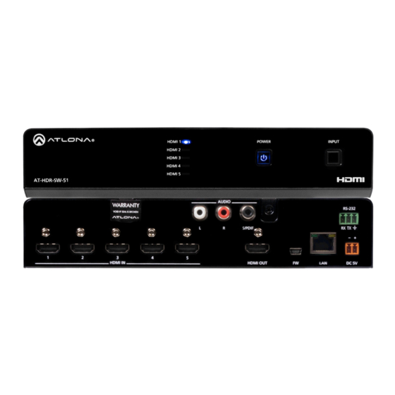
Panel Description Front Panel HDMI 1 POWER INPUT HDMI 2 HDMI 3 HDMI 4 HDMI 5 AT-HDR-SW-51 AUDIO OUT HDMI 1 - HDMI 5: Input LED Indicators INPUT RS-232 These LED indicators display which input is routed Press and release this button to cycle through each to the HDMI OUT port. -
Page 9: Rear Panel
HDMI 1 POWER INPUT HDMI 2 HDMI 3 Panel Description HDMI 4 HDMI 5 AT-HDR-SW-51 Rear Panel AUDIO OUT RS-232 S/PDIF RX TX HDMI IN HDMI OUT DC 5V HDMI IN Connect an HDMI cable from each of these ports to Connect an Ethernet cable from this port to the Local an HDMI source. -
Page 10: Installation
HDMI 1 POWER INPUT HDMI 2 HDMI 3 HDMI 4 Installation HDMI 5 Power Connect the included 2-pin captive screw connector to the DC 5V power receptacle on the rear of the unit. The captive screw comes pre-wired as shown AUDIO OUT RS-232 S/PDIF... -
Page 11: Connection Diagram
Installation Connection Diagram Media Player SYST SYST SPEA SPEA P BOX SYST SYST SPEA SPEA Set-Top Box SYST SYST SPEA SPEA Ceiling Speakers SYST SYST IN PU SPEA SPEA W ER AT-GAIN-60 -5 1 -S W -H DR AT-HDR-SW-51 Laptop Display Laptop Laptop... -
Page 12: Ip Configuration
Installation IP Configuration The AT-HDR-SW-51 is shipped with DHCP enabled. Once connected to a network, the DHCP server (if available), will automatically assign an IP address to the unit. If the AT-HDR-SW-51 is unable to detect a DHCP server within 15 seconds, then the unit will use a self-assigned IP address within the range of 169.254.xxx.xxx/16. -
Page 13: Using The Web Server
Installation Using the Web Server The IP mode of the AT-HDR-SW-51 can also be set using the built-in web server. In order to access the web server, the IP address of the AT-HDR-SW-51 must be known. 1. Open the desired web browser and enter the IP address of the AT-HDR-SW-51. 2. -
Page 14: Automatic Private Ip Addressing (Apipa) Mode
Installation • Setting DHCP mode 1. Connect to the AT-HDR-SW-51 using RS-232 or Telnet. 2. At the command line, execute the IPDHCP command using the on argument, as shown. IPDHCP on Once DHCP is enabled, the unit will be assigned an IP address by the DHCP server (if present). Automatic Private IP Addressing (APIPA) Mode If the AT-HDR-SW-51 is unable to detect a DHCP server within 15 seconds, when set to DHCP mode, then Automatic Private IP Addressing (APIPA) will be used to assign the an address within the IPv4 address block 169.254.xxx. -
Page 15: Device Operation
Device Operation LED Indicators The LED indicators on both the front and rear of the unit provide basic information on the current status of the AT- HDR-SW-51. Description HDMI 1 - Solid blue The input is the currently selected (active) input. HDMI 5 The input is not the active input. -
Page 16: Logging In To The Web Server
Device Operation Logging in to the Web Server Most of the AT-HDR-SW-51 operation is handled through the built-in web server. In order to access the web server, the IP address of the unit must be known. Refer to IP Configuration (page 12) for more information. -
Page 17: Logging In After Registration
Device Operation Logging in after Registration 1. Launch the desired web browser and enter the IP address of the AT-HDR-SW-51 in the address bar. 2. Enter the correct username and password in the respective fields. 3. Click the Submit button. 4. -
Page 18: Selecting The Input
Device Operation Selecting the Input Input selection can be performed on the front panel, through the built-in web server, or by executing a command over Telnet. Refer to the API document for the full set of available commands. Using the Web Server 1. -
Page 19: Auto Switching
Device Operation Auto Switching The AT-HDR-SW-51 provides Auto Switching capability, which is enabled by default. This feature will automatically switch the input to the most recently-connected source. If the active source is disconnected, then the input will automatically be switched to the previously-connected source. Enabling / Disabling Auto Switching By default, Auto Switching is enabled on the AT-HDR-SW-51, allowing the unit to automatically switch between inputs when sources are connected or disconnected. -
Page 20: Scaler Pass-Through
Device Operation Scaler Pass-Through Click this toggle switch to enable or disable the scaler pass-through feature. When set to the ON position, 4K content will be down-scaled to 1080p when the output device detects a 1080p display on the output. When set to the OFF position, the output resolution / timing will be the same as the input source. -
Page 21: Notes On Scaling
Device Operation Notes on Scaling The following section provides important information about how the AT-HDR-SW-51 processes 4K (UHD) video signals. • The HDMI OUT port supports up to 4K @ 60 Hz, 12-bit, with HDR. • If the source is 4K, and the output port is connected to a 1080p (not 4K-capable) display, then the output will be down-scaled as follows: Input Output... -
Page 22: Audio Management
Device Operation Audio Management The AT-HDR-SW-51 provides independent audio muting. Audio muting can be controlled on the L/R and HDMI OUT ports. To de-embed the source audio to the L/R port, connect an RCA cable to both the L and R ports. De-embedding audio is restricted to two-channel Linear PCM formats. -
Page 23: Analog Audio Output
Device Operation Analog Audio Output The AT-HDR-SW-51 features a separate L and R ports on the rear panel. These ports provides de-embedding and conversion of two-channel LPCM audio streams to analog audio. 1. Log in to the web server. 2. Click A/V Settings in the menu bar. 3. -
Page 24: S/Pdif Audio Muting
Device Operation S/PDIF Audio Muting 1. Log in to the web server. 2. Click A/V Settings in the menu bar. 3. Locate the Audio section. 4. Click the S/PDIF Output toggle switch to the OFF position. To re-enable the audio on the S/PDIF OUT port, set the toggle switch to the ON position. -
Page 25: Hdcp Content
Device Operation HDCP Content Transmitting HDCP content to a display that is not HDCP compliant can result in “snow”, image flickering, or no picture. In the illustration below, a laptop source is connected to the AT-HDR-SW-51, which is connected to a display that is not HDCP compliant. -
Page 26: Rs-232 Control
Device Operation RS-232 Control The RS-232 port is used to directly control the AT-HDR-SW-51 using a control system. 1. Log in to the web server. 2. Connect the RS-232 cable between the control system and the RS-232 port on the AT-HDR-SW-51. The included 3-pin captive screw should be wired as shown. -
Page 27: Edid Management
Device Operation EDID Management Before a source can send picture and sound to a display device, the source reads the EDID (Extended Display Identification Data) stored in the display. The EDID contains information about what type of video and audio formats are supported by the display. -
Page 28: Edid Presets
Device Operation EDID Presets The AT-HDR-SW-51 provides the option of selecting a preset EDID. The following presets are available. EDID Description Connected Display (Default) Uses the downstream EDID of the connected display ATL 4K60 MCH 3840 x 2160 (UHD) with multichannel audio support ATL 4K60 PCM MCH 3840 x 2160 (UHD) with PCM multichannel audio support ATL 1080P MCH... -
Page 29: Storing Edid Data
Device Operation Storing EDID Data The AT-HDR-SW-51 provides eight memory locations which can be used to store EDID data. Any downstream EDID can be captured and stored in these locations. Each memory location is non-volatile and captured EDID data is stored after power is disconnected from the unit. - Page 30 Device Operation 6. Click the Save button next to the drop-down list for the memory location. 7. The saved EDID will appear next to the memory location, as shown below. Saved EDID AT-HDR-SW-51...
- Page 31 Device Operation 8. Click any of the input drop-down list boxes. Note that the stored EDID appears as an available EDID preset for each available input on the AT-HDR-SW-51. Saved EDID NOTE: Once an EDID is written to a memory location, it can be overwritten with a different EDID, when desired.
-
Page 32: User Management
Device Operation User Management The AT-HDR-SW-51 allows the login credentials to be changed. The username and password applies to both the web server and Telnet sessions. 1. Log in to the web server. 2. Click Config in the menu bar. 3. -
Page 33: System Configuration
Device Operation System Configuration The AT-HDR-SW-51 provides easy access to system configuration through the built-in web server, and is the recommended method to adjust network settings. Getting the MAC Address 1. Log in to the web server. 2. Click System in the menu bar. 3. -
Page 34: Changing The Telnet Port
Device Operation 3. Locate the IP Mode toggle switch. The default setting of this toggle switch is DHCP. 4. Click this toggle switch to set it to STATIC IP. 5. Enter the desired IP address for the AT-HDR-SW-51 in the IP field. 6. -
Page 35: Telnet Login Mode
Device Operation Telnet Login Mode When a Telnet session is requested, the AT-HDR-SW-51 provides the option to prompt for user credentials or bypass authentication before the Telnet session begins. This credentials prompt option can be enabled or disabled. When prompting for user credentials, use the same login information required by the built-in web server. 1. -
Page 36: Broadcast
Device Operation Broadcast This feature determines whether or not systems changes are announced over TCP/IP connections to any listening devices. 1. Log in to the web server. 2. Click System in the menu bar. 3. Click the Broadcast toggle switch to the desired setting. Setting Description System changes will be announced over TCP/IP connections to any device... -
Page 37: Locking / Unlocking The Front Panel
Device Operation Locking / Unlocking the Front Panel To prevent accidental pressing of the front panel buttons, the front panel buttons can be locked. This may be desirable if, for example, the AT-HDR-SW-51 is installed in a rack environment. By default, the front panel buttons are unlocked. -
Page 38: Resetting To Factory Defaults
Device Operation Resetting to Factory Defaults Using the Web Server The following procedure will reset the AT-HDR-SW-51 to factory-default settings. The network IP mode will be set to DHCP mode. 1. Log in to the web server. 2. Click System in the menu bar. 3. -
Page 39: Using The Front Panel
Device Operation Using the Front Panel 1. Press and hold both the POWER and INPUT buttons for 15 seconds. 2. Release both POWER and INPUT buttons once the front panel LED indicators turn on. After two seconds, the front panel LED indicators will turn off. POWER button INPUT button HDMI 1... -
Page 40: Configuration And Management Interfaces
Configuration and Management Interfaces Web Server The AT-HDR-SW-51 includes a built-in web server. Atlona recommends that the web server be used to set up the AT-HDR-SW-51, as it provides intuitive management of all features. Refer to Logging in after Registration (page for more information. -
Page 41: Login Page
Configuration and Management Interfaces Login page Username Enter the username in this field. Password Enter the password in this field. Submit Click this button to log in. AT-HDR-SW-51... -
Page 42: Info Page
Configuration and Management Interfaces Info page System Info Model Name The model SKU of this product. Software Version The version of firmware that the AT-HDR-SW-51 is running. Always make sure to check the AT-HDR-SW-51 product page, on the Atlona web site, for the latest version of firmware. On-Time (d-h:m:s) Displays the amount of time elapsed since the unit was powered. -
Page 43: A/V Settings Page
Configuration and Management Interfaces A/V Settings page The A/V Settings page is divided into three sections: Video, Audio, and HDCP. The Video section provides controls for switching modes and input selection. The Audio section provides options to control the output audio volume and de-embedding. - Page 44 Configuration and Management Interfaces Audio HDMI Output 1 Set this toggle to the OFF position to mute the audio on the HDMI OUT 1 port. Analog Output Click this toggle switch enable or disable audio output on the L/R port. S/PDIF Output Click this toggle switch enable or disable audio output on the S/PDIF OUT port.
- Page 45 Configuration and Management Interfaces RS-232 page RS-232 RS-232 Console Sets the RS-232 port settings used for local control by a third-party control system. Parameter Description Sets the baud rate. The following options are available: 2400, 4800, 9600, 19200, Baud rate 38400, 57600, 115200.
-
Page 46: Edid Page
Configuration and Management Interfaces EDID page EDID Settings Click these drop-down lists to select the desired EDID to be used for each input. The following EDID presets are available. When selecting an EDID, make sure that the display/sink device is capable of supporting the resolution/ timing. -
Page 47: Config Page
Configuration and Management Interfaces Config page Configuration Old Username Enter the current username in this field. Old Password Enter the current password in this field. New Username Enter the new username in this field. New Password Enter the new password in this field. Confirm New Password Verify the new password by retyping it in this field. -
Page 48: System Page
Configuration and Management Interfaces System page System MAC address Displays the MAC address of the AT-HDR-SW-51. IP Mode Click this toggle to set the IP mode of the AT-HDR-SW-51. Setting Description DHCP Uses an available DHCP server to assign an IP address. STATIC IP Allows the IP address, subnet mask, and gateway IP address to be entered manually. - Page 49 Configuration and Management Interfaces Telnet Timeout Sets the Telnet timeout interval, after no activity, in seconds. Acceptable integer values are: 0 - 60000. The default setting is 300. Once the interval has expired, the Telnet session will be closed. If this field is set to 0, then the timeout interval is infinite.
-
Page 50: Appendix
Appendix Updating the Firmware Updating the firmware can be completed using either the USB interface or the web server. Atlona recommends using the web server for updating the MCU firmware. However, if a network connection is not available, the AT-HDR- SW-51 firmware can be updated using a USB-A to mini-USB cable. -
Page 51: Using Usb
Appendix Using USB Required items: • AT-HDR-SW-51 • Computer containing the firmware file. • USB-A to mini-USB cable NOTE: USB update is not supported on macOS ® HDMI 1 POWER INPUT HDMI 2 HDMI 3 HDMI 4 1. Disconnect power from the AT-HDR-SW-51. HDMI 5 AT-HDR-SW-51 2. -
Page 52: Mounting Instructions
Appendix Mounting Instructions The AT-HDR-SW-51 includes two mounting brackets, which can be used to attach the unit to any flat surface. Use the two enclosure screws, on the sides of the unit to attach the mounting brackets. Single Unit Rack Installation 1. -
Page 53: Dual Unit Rack Installation
Appendix Dual Unit Rack Installation 1. Turn both units upside-down on a flat surface, next to each other, as shown. 2. Position the included mounting plate over the pre-drilled holes on the bottom of the enclosure. When attaching the mounting plate, the countersink bevels on the mounting plate should face upward. Countersink bevel F I E P L I... -
Page 54: Flat Surface
Appendix Flat Surface 1. Turn the unit upside down, on a flat surface. 2. Position the included mounting plates over the pre-drilled holes on the bottom of the enclosure. When attaching mounting plates, the countersink bevels on the mounting plates should face upward. F I E P L I D I O... -
Page 55: Specifications
Appendix Specifications Video Signal Input - HDMI Output - HDMI Copy Protection HDCP 2.2 Pixel Clock 600 MHz UHD/HD/SD 4096x2160 (DCI) @ 24/25/30/50/60 Hz 720x576p @ 50 Hz 3840x2160 (UHD) @ 24/25/30/50/60 Hz 720x576i @ 25/50 Hz 1920x1080p @ 720x480p @ 60 Hz 23.97/24/25/29.97/30/50/60 Hz 640x480p @ 60 Hz 1920x1080i @ 50/60 Hz... - Page 56 Appendix RS-232 Port 1 x 3-pin captive screw Unit and external device control and configuration Baud Rates 2400, 4800, 9600, 19200, 38400, 57600, 115200 Data Flow Bidirectional Resolution / Distance 4K/UHD - Feet / Meters 1080p - Feet / Meters HDMI IN/OUT Buttons and Indicators Buttons:...
- Page 57 Appendix Compliance NDAA-889 Warranty Device To view the product warranty, use the following link: https://atlona.com/warranty AT-HDR-SW-51...
- Page 58 International atlona.com 408.962.0515 41.43.508.4321 • • 35293-R3...
Need help?
Do you have a question about the ATLONA AT-HDR-SW-51 and is the answer not in the manual?
Questions and answers