Table of Contents
Advertisement
Quick Links
DATA LOGGER
PCE-P30U
USER'S MANUAL
PCE Americas Inc.
711 Commerce Way
Suite 8
Jupiter
FL-33458
USA
From outside US: +1
Tel: (561) 320-9162
Fax: (561) 320-9176
info@pce-americas.com
www.pce-instruments.com/english
www.pce-instruments.com
PCE Instruments UK Ltd.
Unit 11
Southpoint Business Park
Ensign way
Hampshire / Southampton
United Kingdom, SO31 4RF
From outside UK: +44
Tel: (0) 2380 98703 0
Fax: (0) 2380 98703 9
info@industrial-needs.com
1
Advertisement
Table of Contents

Related Manuals for PCE Instruments PCE-P30U


Summary of Contents for PCE Instruments PCE-P30U
- Page 1 PCE Americas Inc. PCE Instruments UK Ltd. 711 Commerce Way Unit 11 Suite 8 Southpoint Business Park Jupiter Ensign way FL-33458 Hampshire / Southampton United Kingdom, SO31 4RF From outside US: +1 From outside UK: +44 DATA LOGGER Tel: (561) 320-9162...
-
Page 2: Table Of Contents
4.1. Mounting method ....................9 4.2. External connections diagrams............... 10 5. OPERATION ........................11 5.1. PCE-P30U transducer front panel description ........... 11 5.2. Messages after switching on the power ............12 5.3. Key functions ......................13 5.3.1. Individual key functions................13 5.3.2. - Page 3 5.5.1.6. Mathematical operations on measured values ......46 5.5.1.7. Mathematical functions ............... 48 5.5.1.8. Input individual characteristic ............48 5.5.1.9. Displayed value range limitation ............50 5.5.2. Analog output ....................50 5.5.2.1. Analog output individual characteristic ........50 5.5.2.2. Analog output overflow management .......... 51 5.5.3.
- Page 4 5.9.2. MODBUS protocol description ..............81 5.9.3. Description of the implemented functions ......... 82 5.9.4. Register map ....................86 5.9.5. Read and Write registers ................89 5.9.6. Read-only registers ..................110 5.10. 10/100-BASE-T Ethernet interface .............117 5.10.1. Connecting 10/100-BASE-T Ethernet interface ......117 5.10.2.
-
Page 5: Application
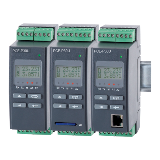
1. APPLICATION The PCE-P30U programmable transducer is designed to convert tem- perature, resistance, direct voltage and direct current signals into a standard DC voltage or DC current signal. The output signal is galva- nically isolated from the input signal and power supply. The transducer is fitted with a 2x8 LCD screen. - Page 6 RS-485 interface Monitor mode – ability to monitor transmission on RS-485 interface and react to the value of the selected register. • 10/100 BASE-T Ethernet interface (option) • protocol: Modbus TCP/IP, HTTP, FTP, • services: WWW server, FTP server, DHCP client Fig.1. Various variants of PCE-P30U transducer.
-
Page 7: Transducer Set
2. TRANSDUCER SET - PCE-P30U transducer 1 pc. - user’s manual 1 pc. - plug-able screw terminal blocks 4 pcs. 3. BASIC REQUIREMENTS, OPERATIONAL SAFETY The transducer meets the requirements of EN 61010-1 standard in terms of operational safety. Safety precautions: •... -
Page 8: Installation
4. INSTALLATION 4.1. Mounting method PCE-P30U transducers should be mounted on a 35 mm rail bracket according to PN-EN 60715. Dimensions and method of mounting are shown in figure 2. Lock Fig.2. Overall dimensions and method of mounting the transducer. -
Page 9: External Connections Diagrams
4.2. External connections diagrams Fig.3. External connections diagram of the PCE-P30U transducer For the connection of input signals in environments with a high noise level, shielded wires should be used. -
Page 10: Operation
5. OPERATION 5.1 PCE-P30U transducer front panel description Fig.4. Front panel description Note: The memory card (option) should be inserted to the transducer slot with contacts facing down LED indicator description: RX – green diode – Data reception on RS-485 indicator... -
Page 11: Messages After Switching On The Power
LED (power indicator), the transdu- cer displays the type, current firmware version and the serial number. If the transducer is equipped with Ethernet interface (PCE-P30U-X2XXXXXX) IP address is displayed after serial number (stored in memory or received from the DHCP server). -
Page 12: Key Functions
After about five seconds, transducer automatically switches to operating mode; it makes a measurement and converts it into an analog output signal. It displays the measured value in the top row of the display and auxiliary information in the bottom row of the dis- play (section 5.5.4). - Page 13 - change digit key • displays the minimum value of the main input, • enters the parameters group level, • navigates the selected level, • changes the value of a selected parameter – switches to the sub- sequent digit, • switching the transducer power supply on while holding this key enters the software update mode through the RS-485 interface, connection parameters: rate 15200 kb/s, mode 8N2.
-
Page 14: Functions Of Key Combinations
5.3.2. Functions of key combinations - hold for about 3 seconds • clear alarm indication; this action works only when the alarm indication memory function is switched on; - hold for about 1 second • clears the maximum value for the measured value - hold for about 1 second •... -
Page 15: Programming Matrix
5.3.3. Programming matrix Fig.7. PCE-P30U operation algorithm... -
Page 16: Programming Transducer Parameters
5.4. Programming transducer parameters Press hold about seconds to enter the programming matrix. If access is password protected, transducer will ask for password. If the entered password is incorrect, Err.Code message will be displayed. Correct password enables access to the programming matrix. Fig. 8 shows the matrix in the programming mode. - Page 17 Median Comp.Val Input Settings AvgTime Compens. Input Number Manual com- of median Measured Averaging Compensa- pensation filter value type time tion type value samples Input parameters Point No Settings Ind.Char The first The first Number of point of the …. The last point Individual point of the...
- Page 18 Math Fun Mathematical function on measured value The last point of the indivi- dual char. Dec.P 2 Unit2 Disp.Reg Bckl.Int Number Minimum of register decimal LCD display Second displayed point of backlight displayed at the lower the second intensity value unit line of the displayed display...
- Page 19 Base.Reg ModeUnit BaudRate No.ofVal Address Number of pol- Number of Transmis- led/monitored polled values Device sion frame Transmission base register Settings in Master / address mode rate in Master/Mo- Mbus 485 Monitor mode nitor mode RS-485 No.OfErr interface Number of parameters acceptable errors in...
- Page 20 Interv. AnswTime Mode ValType Mast.Fun Polling Maximal RS-485 Type of polled Selection of interval in answer interface modbus Master / monitored Master time Master working function values RS-485 mode mode mode Param.SD Ar. Time Ar.Erase Rec.ToSD Percent of internal archive Archiving Copy use which...
-
Page 21: Changing The Value Of The Selected Parameter
5.4.1. Changing the value of the selected parameter increment selected parameter, press Press the key once to increase the value by 1. If value of 9 is incre- ased, the digit will switch to 0. To change the digit, press Press when editing the most significant digit to edit the digit sign character –... -
Page 22: Programmable Transducer Parameters
5.4.3. Programmable transducer parameters The table below shows programmable parameters and the possible ran- ges of values. Table 1 Settings Input Para- meter Description Range of changes symbol Selection Input Displayed symbol Description the input type Voltage -10V … 10V –... - Page 23 Voltage -5...20mV Voltage -5..20mV Voltage -75...75mV Voltage -75..75mV Voltage -200...200mV Voltage -200..200mV Thermocouple J 0...400ºC Therm.J 0..400 Thermocouple J 200...1200ºC Therm.J -200..1200 Thermocouple K 0...400ºC Therm.K 0..400 Thermocouple K -200...1370ºC Therm.K -200..1370 Thermocouple S 0...1760ºC Therm.S -50..1760 Thermocouple N -20...420ºC Therm.N -20..420 Thermocouple N -200...1300ºC Therm.N -200..1300...
- Page 24 C o m p e n s a - Automat. - Automatic compensation Com- pens. tion type of : Manual - Manual compensation - cold junction temperature for thermoco- uples cords sistance measuring re- sistance and temperature from thermo- resistor sen- sors Terminal tem-...
- Page 25 Mathematical Mathematical functions Math Off. function ope- switched off ration on the Square of measured input value Square root of measured √ x value Inverse of measured value Inverse square of measu- 1/x2 red value Inverse square root 1/√ x of measured value Table 2 Settings...
- Page 26 Table 3 Settings Display Parameter Description Range of changes symbol Minimum decimal DecimalP 0.0000 point of the display- 00.000 ed value – display 000.00 format. 0000.0 00000 Displayed unit kVAh Unit MVAh Ω kΩ obr/mi ºC ºF mm/min m/min l/min m3/min kvar szt/h...
- Page 27 Lower display range Over Lo -99999...99999 threshold Upper display range Over Hi -99999...99999 threshold Display backlight - always on Bcklight time Off - always off - active for X seconds … display 10% - LCD display backlight 10% Bckl.Int backlight intensity of maximum backlight 20% - LCD display backlight 20% of maximum backlight...
- Page 28 Table 4 Settings Alarm 1,Alarm 2 Parameter Description Range of changes symbol Input value type displayed value DisplVal Param.A1 alarm 1 Param.A2 time Time the second displayed 2nd Val value Alarm type. Fig.17 shows normal (change from n-on Type A1 graphical illustration of 0 to 1) Type A2...
- Page 29 Alarm indication mode alarm occurrence is SgKeepA1 indicated using LED SgKeepA2 A1/A2, alarm deacti- vation switches LED A1/A2 alarm occurrence is indicated using LED A1/A2, alarm deacti- vation causes blinking of A1/A2 LED’s until the alarm is reconfi- gured or cleared with combination.
- Page 30 Switching analog Overflow manage- OvrIn Lo ment switched off output overflow mana- gement Overflow manage- ment switched on Lower input overflow OvrIn Lo -99999...99999 for output overflows Upper input overflow -99999...99999 OvrIn Hi for output overflows Value expected -24...24 OvrOutLo output on lower overflow Value expected...
- Page 31 38400 bit/s 38400 57600 bit/s 57600 115200 bit/s 115200 230400 bit/s 230400 256000 bit/s 256000 Number polled Base.Reg 0 ... 65536 monitored base register in Master Monitor mode of RS-485 inter- face Number of polled values in No.ofVal 0 ... 50 Master Monitor mode of RS-485 interface...
- Page 32 float type value, 32 flt 2x16 bits floating point va- lue placed on two 16- bit registers (Byte order 1,0,3,2) long type value (32 lng 2x16 bits with sign) placed on two 16-bit registers, (Byte order 1,0,3,2) swapped long type slng2x16 value (32 bits with sign)
- Page 33 RS-485 interface wor- RS-485 interface Slave Mode king mode works Modbus Slave mode, trans- ducer waits for requ- ests and responds on request adressed to its address Transducer moni- Monitor tors trafic on RS-485 interface and acts on data other devices transmitt RS-485 interface...
- Page 34 Table 7 Settings Archive Parameter Description Range of changes symbol Selection archived only displayed value Arch.Val DisplVal values displayed value and Note: changing the re- +2nd Val the second displayed gister value clears the value archive in the internal me- mory!!! displayed value,...
- Page 35 PCE-P30U-X2XXXXXX) Percent of internal ar- … Param.SD chive use which triggers automatic copying SD/SDHC card Table 8 Settings Ethernet (option, only variant PCE-P30U-X2XXXXXX) Parameter Description Range of changes symbol Switching DHCP client DHCP switched DHCP on/off (enables automatic – manually configure...
- Page 36 Third and second byte 000.000 … 255.255 addrIP32 (B3.B2) of transducer’s IP address, value displayed in a decimal format, IPv4 address format: B3.B2. B1.B0 First zero byte 000.000 … 255.255 addrIP10 (B1.B0) of transducer’s IP address, value displayed in a decimal format, IPv4 address format: B3.B2.
- Page 37 First and zero byte (B1. 000.000 … 255.255 MAC 10 B0) of transducer’s MAC address, value displayed in a decimal format; for- mat B5:B4:B3:B2:B1:B0 Device address for Mod- 0 … 255 AddrmTCP bus TCP/IP protocol Modbus TCP/IP port 0 … 65535 PortMbus number Modbus TCP/IP service...
- Page 38 Table 9 Settings Service Parameter Description Range of changes symbol Restore factory parame- without changes Fabr.Par ters. Choose Yes to write standard parame- ters to the transducer. restores factory para- Factory parameters are meters shown in table 17. Enter password. Security -99999...99999 Enter “0”...
-
Page 39: Transducer Functions
5.5. Transducer functions 5.5.1. Measurement input The PCE-P30U transducer is equipped with universal, configurable measurement input, which enables to measure direct current, direct voltage, resistance and temperature from thermocouples and thermi- stors. Detailed information about supported inputs is shown in table 48. - Page 40 entering value „2” into register 4042. Master In the Master mode the following parameters should be configured in the Mbus 485 menu: Table 10 Item Mbus 485 Address of the device being read out Address Transmission mode on the connection ModeUnit Baud rate BaudRate...
- Page 41 In order to make the transducer RS-485 interface work again in the Slave mode, one should select proper mode in menu RS-485 Mbus 485 → Mode → Slave. Supply Fig.9. Example of using a PCE-P30U transducer in the RS-485Master mode to read and register relative humidity from a PCE-P18 transducer.
-
Page 42: Interface Rs-485 Monitor Mode
Monitor device is able to listen to traffic in the RS-485 network and react to spe- cific register of responses of the selected device. The PCE-P30U tran- sducer must have the same communication parameters as the device being listened to. The RS-485 Monitor mode is switched on by selecting the appropriate mode from menu: Mbus 485 →... -
Page 43: Median Filter
Transducer PCE-P30U. This function enables to filter input signal from influence of perturbances on input signal. Parameter Input → Median specifies number of samples from which signal will be filtered - number of samples determines filtering period. For example, if transducer is con- figured for measuring voltage from 0...10 V range (sample rate 80 ms) ,... - Page 44 After switching median filter on with number of samples 5 (sample rate 80 ms) 5 subsequent samples will be sorted and only median sample will be treated as measured value (sample no 3 after sor- ting). After sorting Xn values are as follows: 10.004, 10.0055, 10.0055, 10.0065, 10.025.
-
Page 45: Averaging Time
5.5.1.4. Averaging time Various averaging time of the measured value can be defined in transducer PCE-P30U. Averaging time of measured value can be set within 0.075...0,2...20 s range – the moving window averaging function has been used. The minimal time below 0,2 s can only be used... -
Page 47: Mathematical Functions
5.5.1.7. Mathematical functions The PCE-P30U transducer can calculate the measured values using one of 5 implemented mathematical functions: • square of measured value, • root of measured value, • inverse of measured value, • inverse square of measured value, •... - Page 48 Fig.13. Input individual characteristic During function approximation, must remember that in the case of approximating curves that significantly deviate from linear characteristics, the higher number of linearising sections, the lower the linearisation error. If the measured values are lower than X1, then the calculations will be made based on the first straight line calculated based on points (X1,Y1) and (X2,Y2).
-
Page 49: Displayed Value Range Limitation
+1e20. 5.5.2. Analog output The PCE-P30U transducer is equipped with one current type (source) or voltage type analog output depending on the variant code. 5.5.2.1. Analog output individual characteristic... -
Page 50: Analog Output Overflow Management
Fig.14. Analog output individual characteristic 5.5.2.2. Analog output overflow management PCE-P30U transducer user additionally configure the behaviour of the analog output after controlling output value over- flow. By default, overflow management is switched off – in such a case, after controlling output value is overflowed, the output is still controlled proportionally to the controlling output value outside the basic range of the output. - Page 51 Table 12 Parameter Parameter value Register Register symbol in the symbol value menu in the menu 4040 Param.An DisplVal 4041 OverServ 7610 AnIn Lo 7611 1000 AnIn Hi 1000.0 7612 AnOut Lo 7613 AnOut Hi 20.0 Fig. 15 shows the reaction of the analog output when analog output overflow management is switched off –...
- Page 52 If in the same case the analog output overflow management is switched on (parameters set according to table 13), the reaction of the analog output will be as is shown on fig. 16. Table 13 Parameter Parameter Register Register no. symbol value symbol value...
- Page 53 Temperature [ Fig.16. Operation of the analog output when overflow manage- ment is switched on Example 2: Configuration of the analog output controlled by real time clock The transducer set to measure temperature form Thermocouple J: individual characteristic current Therm.J 0..400 type analog output is set, that the output reacts to current time (hour, minute), i.e.
-
Page 54: Alarm And Power Outputs
5.5.3. Alarm and power outputs The PCE-P30U transducer is equipped with 2 relay alarm outputs with a normally open contact or with 1 relay output with a normally open contact and 1 power supply output 24 V d.c. (depending on the ma- nufacturing variant code). - Page 55 Fig.17. Alarm types: a) n-on; b) n-off; c) on; d) off. AL_L - Lower alarm threshold AL_H – Upper alarm threshold Note: If alarms are n-on, n-off, on, off type, entering AL_L > AL_H will switch off the alarm.
-
Page 56: Lcd Display
5.5.4. LCD display The PCE-P30U transducers are equipped with a backlit LCD display con- sist of two lines of 8 characters each. The top line of the display is used for presenting the displayed value in floating point format (5 digits) and for... - Page 57 - lower overflow of the input signal range - upper overflow of the input signal range The lower line of the PCE-P30U transducer display is multi-func- key to cycle through the functions tional. Press of the bottom row of the display: •...
-
Page 58: Custom Unit Definition
5.5.4.1. Custom unit de definition In the transducers of the PCE-P30U family, apart from the defined stan-dard units, it is possible to define user own unit to be displayed in the lower line of the LCD display. The maximum size of the unit field is 5 characters, each character consists of 8 lines which makes 5x8 = 40 fields (registers) that define the unit. -
Page 59: Displaying Two Values With Their Units
5.5.4.2. Displaying two values with their units PCE-P30U transducer enables displaying two different values witch their units - displayed value at the top row of display and the second displayed value (value of any transducer register) at the bottom row of the display. -
Page 60: Writing And Reading Transducer Configuration From File
The configuration file should be located in PCE-P30U folder and its name should be PCE-P30U_PAR.CON. The file can be generated by a properly configured PCE-P30U trans- ducer or by eCon software (Modbus RS-485 or TCP/IP). In case of... -
Page 61: Default Settings
FTP protocol. In case of PCE-P30U-X1XXXXXX manufacturing variants, a single external memory card can be used to transfer configuration to multiple transducers equipped with external SD card slots. To force parameter update from file, switch on the transducer while pres- sing key. - Page 62 Table 17 Parameter symbol Standard value Therm.J 0..400 o C Input AvgTime 1000 Compens. Automat. Comp.Val Median Math Fun Off.. Point No 0,0000 0,0000 (n-1)*100 (n-1)*100 DecimalP 0.0000 Unit Over Lo -99999 Over Hi 99999 Bcklight Bckl.Int 70,00% Disp.Reg 7515 Dec.P 2 0.0000 DecimalP...
- Page 63 Param.A1 Param.A2 DisplVal Type A1 Type A2 n-on OverLoA1 OverLoA2 OverHiA2 OverHiA2 DlyOnA1 DlyOnA2 DlyOffA1 DlyOffA2 OnLockA1 OnLockA2 SgKeepA1 SgKeepA2 Param.An DisplVal AnIn Lo AnIn Hi AnOut Lo AnOut Hi OverServ OvrIn Lo OvrIn Hi OvrOutLo OvrOutHi Address ModeUnit r8n2 BaudRate 9600 Base.Reg...
- Page 64 Mast.fun 0x03 No.ofErr Arch.Val DisplVal Param.Ar DisplVal Ar. Mode h-off OverLoAr 0,0000 OverHiAr 0,0000 Time Ar Ar.Erase Rec.ToSD Param.SD 50,000 Fabr.Par Security 00000 undefined Time undefined Date AutoTime DispTest Polski (PCE-P30U-XXXXXXPX Language viariants) English (PCE-P30U-XXXXXXEX viariants) SaveFile...
- Page 65 DHCP addrIP32 192.168 addrIP10 001.030 mask 32 255.255 mask 10 255.000 gate 32 192.168 gate 10 001.001 MAC 54 Various value – specific to each MAC 32 transducer MAC 10 AddrmTCP PortMbus TimeMbus no.c.TCP p.comFTP Port FTP 1025 PortHTTP LnkSpeed Auto EthStdPa ReInitEt...
-
Page 66: Firmware Update
5.7. Firmware update PCE-P30U transducer enables firmware update b y u ser u sing PC computer with eCon software installed. free eCon software and update files are available at www.pce- instruments.com RS-485 to USB converter, e.g. PCE-PD10 converter, is required for proceeding with the update. - Page 67 If the transducer establishes communication with UPDATER software, Device found: PCE-P30U message and the version of the main firm-ware and bootloader will be displayed, as well as the Device is ready message will be shown on the transducer display.
-
Page 68: Archiving Measured Values
5.8. Archiving measured values 5.8.1. Transducer memory structure Standard PCE-P30U transducers (regardless of the manufacturing variant code) are equipped with a 4MB internal memory for storing data recorded by the transducer. The default recorded parameter is the displayed value, that is the measured value or value converted using mathematical functions and individual input characteristic. -
Page 69: Internal Memory
Note: Changing the Archive → Arch.Val parameter value menu will delete archive in the internal memory!!! 5.8.2. Internal memory The internal transducer memory is divided into 8,192 pages. Each memory page can store 66 archive data records. Records on the page always begin from the page beginning and occupy the entire space of the page. -
Page 70: Record Structure
Table 18 Symbol Percent of internal memory used 5.8.2.1. Record structure All data contained in the internal data memory are stored as records consisting of 8 bytes. The record structure has been presented in the table below. Table 19 Internal memory record (8 Bytes) Recording time (4 Bytes) Data archived in float format (4 Bytes) Year- 2010... -
Page 71: Downloading Archived Data From The Internal Memory
Table 20 Register HEX value 4553 0x0170 4554 0xBB95 4555 0xE87C 4556 0xB942 rec = 0x0170BB95E87CB942 Data = 0xE87CB942 → (float) → 92.743958; Table 21 Recording time = 0x0170BB95 → b1011100001011101110010101 Year + 2010 Month Hour Minute Second 6 bytes 4 bytes 5 bytes 5 bytes... -
Page 72: Archiving Configuration
archive data). To do this, insert the SD/SDHC card in the transducer slot (contacts facing down) and make sure that the card has been properly mounted (the top right corner of the display shows a card icon ). The percent value of archive use, at which the data will automatically be copied to the card or to the file internal file sy- stem memory, must be set. - Page 73 Triggering conditional archiving can be implemented using one of four options presented in figure 25 (n-on, n-off, off, on). Continuous archiving is switched on by selecting the archiving type h-on, and it is switched off by selecting the option h-off.
- Page 74 Fig.25. Conditional archiving types Ar_L - Lower archiving threshold → OverLoAr → Register 7608 Ar_H – Upper archiving threshold → OverHiAr → Register 7609 Example 4: Example 4: The transducer is configured for measure- ment of temperatur - input C. Conditional archi- Pt100 -200..850 ving of both displayed values triggered by the displayed value level: Table 22...
-
Page 75: Memory Card Or Internal File System Memory (Option)
FAT and FAT32 file systems are supported. If the memory card is not formatted, it should be formatted in the card reader using a PC. PCE-P30U transducer creates folders and files during operation, containing archive data. Before inserting the card into the transducer,... - Page 76 Do not remove the memory card from the transducer before it is un- mount (see section 5.3.2.) – unmount the card by pressing the following keys: If a mounted card is removed, the corruption of the data stored on the memory card can be damaged. The memory card status is described in the transducer registers (sections 5.9.6, table 46).
- Page 77 During the operation, the PCE-P30U transducer creates folders and files on the SD/SDHC memory card or in the internal file system memory. An example folder structure is shown on fig. 27. Fig.27. Folder structure on the memory card (internal file system) Apart from the ARCH folder where recorded data are stored, also the SYSTEM folder is created on the memory in which the start.txt file is...
-
Page 78: Archive File Structure
5.8.5. Archive file structure Files containing archive data on an external SD/SDHC card or in the file system internal memory have a column structure, where the subsequent data columns are separated from another by a tab character. The first row contains the column header. Data records are placed in order in rows, and the fields of a given record are separated from one another with a tab character. -
Page 79: Interface
5.9. RS-485 Interace The digital programmable PCE-P30U transducers are equipped with a serial interface in the RS-485 standard to communicate in computer systems and with other Master devices. Asynchronous character com- munication protocol MODBUS has been implemented on the serial in- terface. -
Page 80: Modbus Protocol Description
Fig.29. Method of connecting the RS-485 interface The PC card transmission line marking depends on the card manufacturer. 5.9.2. MODBUS protocol description The implemented protocol complies with Modicon’s PI-MBUS-300 Rev G specification. PCE-P30U MODBUS protocol serial interface parame- ters : • Transducer address 1..247. •... -
Page 81: Description Of The Implemented Functions
• identical baud rate and type of information unit. 5.9.3. Description of the implemented functions The following MODBUS protocol functions have been implemented in PCE-P30U transducers: • 03 (03h) – Read Holding Registers • 04 (04h) – Read Input Registers •... - Page 82 Response: Table 25 Register value Register value 1DB0 (7600) 1DB1 (7601) E46Fh Example 6: Example 8. Reading two float 32-bit registers (7501,7502) located in 2x2 following 16-bit registers (7002, 7003, 7004, 7005), first register address is 1B5Ah (7002) – 32-bit register values: 25.68, 20.25.
- Page 83 Reading two float 32-bit registers (7501,7502) located Example 7. in 2x2 following 16-bit registers (6002, 6003, 6004, 6005), first register address is 1772h (6002) - 32-bit register values: 25.68, 20.25. Request: Table 28 Register Number Device Fun- address of registers address ction E1A6h...
- Page 84 Response: Table 31 Register Number Device Fun- address of registers address ction 9B94h Write Multiple registers (code 10h) Example 9. Writing value “20” and “200” to registers 1DB0h (7600) and 1DB1h (7601) Request: Table 32 Register value Register value 1DB1 1DB0 (7600) (7601) C9E2h...
-
Page 85: Register Map
4304, 4305 see table 41 manufacturing status 1, manufacturing status 2. 5.9.4. Register map In the PCE-P30U transducer the data is stored in 16- and 32-bit registers. The process variables and parameters of the device are stored in the different address space depending on the variable type. - Page 86 Table 36 Address Value type Description range integer 4000 - 4127 The value is located in the 16-bit register (16 bits) integer 4300 - 4325 The value is located in the 16-bit register (16 bits) integer 4400 - 4439 The value is located in the 16-bit register (16 bits) integer 4500 - 4764...
- Page 87 The value is located in the 32-bit register. float 7600-7668 Registers can be read and written. Byte order (32 bits) (B3,B2,B1,B0) The value is located in the 32-bit register. float 8000-8049 Registers can be read and written. Byte order (32 bits) (B3,B2,B1,B0) The value is located in two following 16-bit regi- float...
-
Page 88: Read And Write Registers
5.9.5. Read and Write registers Table 37 Description 4000 0...34 Input type Input Value reserved Voltage -10…10V Voltage -24…24V Current -20...20mA Resistance 0...400Ω Resistance 0...2000Ω Resistance 0...5500Ω Pt100 -200...850 ºC Pt250 -200...600 ºC Pt250 -200...850 ºC Pt500 -200...180 ºC Pt500 -200...850 ºC Pt1000 -200...250 ºC Pt1000 -200...850 ºC Ni100 -60...180 ºC... - Page 89 Ni1000-LG -60...180 ºC Cu100 -50...180 ºC Voltage -5...20mV Voltage -75...75mV Voltage -200...200mV Thermocouple J 0...400ºC Thermocouple J -200...1200ºC Thermocouple K 0...400ºC Thermocouple K -200...1370ºC Thermocouple S 0...1760ºC Thermocouple N -20...420ºC Thermocouple N -200...1300ºC Thermocouple E -40...260ºC Thermocouple E -200...1000ºC Thermocouple R 0...1760ºC Thermocouple T -200...400ºC Thermocouple B 400...1800ºC...
- Page 90 4004 0...3 Clears minimum and maximum values with time EraseExt and date of occurrence on the main input Value Description without changes erasing minimum value erasing maximum value erasing minimum and maximum value 4005 0...10 Number of acceptable errors in modbus RS-485 No.OfErr answers when transducers interface works...
- Page 91 4019 1...10 Value Description Bckl.Int LCD display backlight 10% of maximum backlight LCD display backlight 100% of maxi- mum backlight 4020 0...57 Displayed unit Unit. Unit Unit Unit kVAh MVAh Ω kΩ obr/mi ºC ºF mm/min m/min l/min /min kvar szt/h Mvar km/h...
- Page 92 4021 0...4 Minimum decimal point of the displayed value DecimalP – display format. Value Description 0.0000 00.000 000.00 0000.0 00000 4022 0….61 Bcklight LCD display backlight time Value Description always off 1..60 active for 1...60 seconds always on 4023 0...57 Second displayed value unit, values similar to Unit 2 register 4020...
- Page 93 4027 Typ A1 Alarm 1 type (description – section 5.5.3.) Value Description n-on n-off h-on h-off 4028 0...900 DlyOnA1 Alarm 1 activation delay (s) 4029 0...900 DlyOffA1 Alarm 1 deactivation delay (s) 4030 0...900 OnLockA1 Alarm 1 reactivation delay (s) 4031 0...1 Alarm 1 indication mode...
- Page 94 4034 Typ A2 Alarm 2 type (Description – section 5.5.3.) Value Description n-on n-off h-on h-off 4035 0...900 DlyOnA2 Alarm 2 activation delay (s) 4036 0...900 OpoWylA2 Alarm 2 deactivation delay (s) 4037 0...900 OpoPonA2 Alarm 2 reactivation delay (s) 4038 0...1 Alarm 2 indication mode...
- Page 95 4041 0...1 Analog output overflow management OverServ Value Description Switched off Switched on 4042 0...2 RS-485 interface working mode Mode RS-485 interface works in modbus Slave mode, transducer waits for requ- ests and responds on request adressed to its address Transducer monitors trafic on RS-485 interface and acts on data other devices transmitt...
- Page 96 4046 0..1 Selection of modbus Master function Mast.Fun function 0x03 function 0x04 4047 RESERVED 4048 10...5000 1000 The maximal response time of the device working AnswTime in Master or Monitor RS-485 interface mode [ms] 4049 0...12 Type of polled / monitored values in either ValType Master or Monitor RS-485 interface mode char type value (8 bits with sign)
- Page 97 4050 0...65535 7510 Number of polled / monitored base register Base.Reg in Master / Monitor mode of RS-485 interface 4051 0...50 Number of polled values in Master / Monitor No.ofVal mode of RS-485 interface 4052 1...36000 Interw. Polling interval in Master RS-485 mode 4053 0...1 Update...
- Page 98 4061 2001... Current year in YYYY format ...2099 4062 0...1 Auto change of summer/winter time and vice versa Value Description Switched off Switched on 4063 RESERVED 4064 0...2 Select archived values Arch.Val Note: changing register value clears the archive in the internal memory!!! Value Description displayed value only –...
- Page 99 Archiving period (s) Time Ar 4068 0...1 Ar.Erase Erasing internal archive 4069 0...1 Copy internal archive into SD/SDHC card Rec.ToSD (variant PCE-P30U-X1XXXXXX) or into internal file system memory (variant PCE-P30U- -X2XXXXXX) Value Description without changes start copying the archive 4070..
- Page 100 4083 0...65535 Third and second byte (B3.B2) of transducer’s 65535 mask 32 subnet mask, value displayed in decimal format, mask format: B3.B2.B1.B0 4084 0...65535 First and zero byte (B1.B0) of transducer’s sub- 65280 mask 10 net mask, value displayed in a decimal format, mask format: B3.B2.B1.B0 4085 0...65535...
- Page 101 4093 20...65535 1025 Port FTP FTP server data port number 4094 1...4 Maximum number of simultaneous connections no.c.TCP with Modbus TCP/IP service 4095 10...600 Modbus TCP/IP service port closing time, TimeMbus the value is given in seconds 4096 0...255 AddrmTCP Device address for Modbus TCP/IP protocol 4097 0...65535...
- Page 102 Table 38 Register address (16 bit registers, Description (1 n 5) 4400+8*(n-1) 0...31 Filling custom unit character n of line 1 (section 5.5.4.1.) 4401+8*(n-1) 0...31 Filling custom unit character n of line 2 (section 5.5.4.1.) 4402+8*(n-1) 0...31 Filling custom unit character n of line 3 (section 5.5.4.1.) 4403+8*(n-1) 0...31...
- Page 103 Table 40 Symbol Range Description 6200...6203 7600 RESERVED /7200..7203 6204/7204 7602 -99999... Lower display range -99999 Over Lo ..99999 threshold 6206/7206 7603 -99999... 99999 Upper display range Over Hi ...99999 threshold 6208/7208 7604 -99999... Lower alarm 1 thres- OverLoA1 ...99999 hold 6210/7210 7605...
- Page 104 6220/7220 7610 -99999... Analog output indi- AnIn Lo ...99999 vidual characteristic – lower input thres- hold 6222/7222 7611 -99999... Analog output indi- AnIn Hi ...99999 vidual characteristic – upper input thres- hold 6224/7224 7612 -24...24 Analog output indi- AnOut Lo vidual characteristic –...
- Page 105 6256/7256 7628 -99999... Individual characte- ...99999 ristic point no. 4. 6258/7258 7629 -99999... Expected value ...99999 for point no.4. 6260/7260 7630 -99999... Individual characte- ...99999 ristic point no. 5. 6262/7262 7631 -99999... Expected value ...99999 for point no.5. 6264/7264 7632 -99999...
- Page 106 6290/7290 7645 -99999... 1100 Expected value for ..99999 point no.12. 6292/7292 7646 -99999... 1200 Individual characte- ...99999 ristic point no. 13. 6294/7294 7647 -99999... 1200 Expected value for ...99999 point no.13. 6296/7296 7648 -99999... 1300 Individual characte- ...99999 ristic point no. 14. 6298/7298 7649 -99999...
- Page 107 6324/7324 7662 -99999... 2000 Individual characte- ...99999 ristic point no. 21. 6326/7326 7663 -99999... 2000 Expected value for ...99999 point no.21. 6328/7328 7664 -99999... Input signal thres- OvrIn Lo ...99999 hold value for lower overflow 6330/7330 7665 -99999... Input signal thres- OvrIn Hi hold value for upper ...99999...
- Page 108 Table 41 Name value 8100/8200 8000 Value of the first read transducer working Master RS-485 in- Monitor terface mode 8102/8202 8001 Value of the 2-th read transducer working Master RS-485 Monitor interface mode 8104/8204 8002 Value of the 3-th read transducer working Master...
-
Page 109: Read-Only Registers
5.9.6. Read-only registers Table 42 Range Description 4300 0...9999 Firmware version * 100 4301 0...65535 Transducer status 1. Describes the current transdu- cer status. The consecutive bits represent a given event. Bit set to 1 means that the event has taken place. - Page 110 Bit4 Default settings must be restored after firmware update Bit3 Wrong configuration of the indi- vidual characteristic Bit2 Settings have been read from file on the SD/SDHC card Bit1 Wrong settings file or file is missing Bit0 not used 4302 0...65535 Transducer status 2.
- Page 111 4303 0...5 Status of the SD/SDHC memory card or file system internal memory Value Description No card inserted or internal file system memory error Card inserted, but not mounted (unmoun- ted) or internal file system memory error. Card inserted, but unmounted or internal file system memory error.
- Page 112 4306 RESERVED 4307 0...8192 Memory page specifying the beginning of the internal archive 4308 0...8192 Memory page specifying the end of the internal archive 4309 0...527 Byte specifying the beginning of the archive. Value in the register specifies from which byte of the archi- ve beginning page the archive beginning is.
- Page 113 Table 43 Name Description 6000/7000 7500 Identifier Constant defining the device. Value “193” means PCE-P30U transducer. 6002/7002 7501 Status Register describes the cur- rent transducer status - value of 4302 register “Status no 2”. 6004/7004 7502 Analog out- Register specifies...
- Page 114 6020/7020 7510 Measured Value currently measured on value the input, not calculated using individual characteristic or mat- hematical functions 6022/7022 7511 Cold ºC Cold junction temperature - junction temperature of transducer ter- temperature minals used for thermocouples temperature compensation 6024/7024 7512 Second Value displayed at the lower...
- Page 115 6050/7050 7525 Minimum Time minimum - time value occurrence on the input HH.MMSS format (e.g. “9.5405” means 09:54:05 o’clock) 6052/7052 7526 Maximum Time of the maximum value - time occurrence on the input in HH.MMSS format 6054/7054 7527 Measured value after opera- tion of individual characteristic and then mathematical function 6056...
-
Page 116: 10/100-Base-T Ethernet Interface
5.10. 10/100-BASE-T Ethernet interface PCE-P30U transducers in PCE-P30U-X2XXXXXX manufacturing variant are equipped with an Ethernet interface enabling connection of the transducer (using RJ45 socket) to the local or global network (LAN or WAN) and using network services implemented in the trans- ducer: WWW server, FTP server, TCP/IP Modbus slave. - Page 117 PCE-P30U to the network hub or switch, • EIA/TIA 568A for the first connector and EIA/TIA 568B for the second connector using the crossover connection, used, among others, in the case of direct connection of the PCE-P30U transducer to the PC.
-
Page 118: Www Server
EPWR- white/brown white/brown EPWR- brown brown 5.10.2. WWW server PCE-P30U transducer provides server enabling remote monitoring of measured values and remote configura- tion as well as reading the transducer status. In particular, the website enables the following: • receiving information about the device (serial number, manufac-... -
Page 119: Website General View
5.10.2.1. Website general view Parameter group Website selection languge menu selection Window with parameters and values presentes on the website Fig.31. View of transducer’s website 5.10.2.2. WWW user selection The transducer has two user accounts for the WWW server protected with individual passwords: •... - Page 120 Fig.32. View of the transducer’s WWW server log in window WWW server user names cannot be changed, but the user passwords can be changed for every user. It is recommended to change the passwords for safety reasons. Password can be changed only through the website in “Ethernet”...
-
Page 121: Ftp Server
5.10.3. FTP server protocol been implemented transducers. The transducer operates in a server FTP mode and enables clients access to the transducer’s internal file system memory. Files can be accessed by a PC, tablet with an installed FTP client software or with another device operating in FTP client mode. - Page 122 user passwords will be restored: user „admin” → password: „admin” ; user „user” → password „passftp”. internet browser basic server client. Enter the transducer’s IP address with “ftp” prefix. f...
-
Page 123: Tcp/Ip Modbus
5.10.4. TCP/IP Modbus PCE-P30U transducers enable access to internal registers using the Ethernet interface and TCP/IP Modbus Slave protocol. The functions of Modbus protocol and structure of registers have been discussed in section 5.9.3-5.9.6. It is required to set an unique IP address for the transducer and to set connection parameters specified in table 45 to set up the connection. -
Page 124: Accessories
6. ACCESSORIES For the transducers in PCE-P30U-X1XXXXXX variants that support SD/SDHC cards user can order an additional industrial SD card with the capacity adapted to the user’s needs according to the table below. It is not recommended to use consumer grade cards due to significant deviations of their parameters and their low durability. - Page 125 Calibration parameters lost – send the transducer Err.CAL to a service, the message does not prevent measured values from being displayed, message is displayed in cycles. Real time clock battery low voltage – loss of real time clock Err Batt presets after a power loss, the transducer can operate, Service consider sending the transducer to a service to replace...
-
Page 126: Technical Data
8. TECHNICAL DATA Inputs: Table 48 -12...12 V Voltage -10..10V -10…10V -28...28 V Voltage -24..24V -24…24V -24…24 mA Current -24..24mA -20…20 mA 0…420 Ω Resistance 400 Ω 0…400 Ω 0…2050 Ω 0…2000 Ω Resistance 2000 Ω 0…5550 Ω 0…5500 Ω Resistance 5500 Ω... - Page 127 -6 … 21 mV Voltage mV -5…20 mV -80 … 80 mV -75…75 mV -210 … 210 mV -200…200 mV -20 … 420 ºC 0…400 ºC Thermocouple J -220 … 1210 ºC -200…1200 ºC -20 … 420 ºC 0…400 ºC Thermocouple K -280 …...
- Page 128 sample rate – input type: Voltage 10 V, 80 ms Voltage -24..24V, Prad -24..24mA – other inputs 160 ms Output: analog output programmable, insulated galvanically, current (0/4...20 mA, load resistance ≤ 500 Ω ) or voltage (0...10 V, load resistance ≥ 500 Ω), analog output accuracy class 0.1;...
- Page 129 Display alphanumeric display characters with LED backlight Warm-up time 15 min Recording Recording into the internal 4 MB memory (max. 534,336 records) – recording with time stamp, for variants compatible with SD/SDHC - possibility to automatically writing internal archive into SD/SDHC cards. Reference conditions and nominal operational conditions supply voltage 85..253 V d.c./a.c.(40..400 Hz) or 20..40 V a.c.
- Page 130 Input parameters resistance of the voltage input -10...10V, -24,...24V: > 1 MΩ resistance of the voltage input Voltage mV, Thermocouple: >100 kΩ resistance of the current input -24...24 mA: 12 ±1 Ω% current flowing through a thermometric resistor < 0,2 mA resistance of cords connecting a thermometric resistor with the transducer: <...
-
Page 131: Ordering Code
9. ORDERING CODE Table 49 PCE-P30U transducer- Analog output: current (0/4...20 mA) voltage (0...10 V) Additional equipment: without any with external SD/SDHC slot With Ethernet interface and internal file system memory Additional output: relay (normally opened) , 5 A 30 V d.c., 250 V a.c. - Page 132 Example of Order The Code PCE-P30U-112100E1 means a transducer in a standard ver- sion with a current analog output, supporting external SD/SDHC cards, with 24 V/30 mA power output, 85...235 V a.c./d.c. power supply, in English language version and a Quality Control Certificate.
Need help?
Do you have a question about the PCE-P30U and is the answer not in the manual?
Questions and answers