Table of Contents
Advertisement
Quick Links
Vibration Data Logger
Model : PCE-VDR 10
OPERAT IO N MANUAL
PCE Americas Inc.
711 Commerce Way
Suite 8
Jupiter
FL-33458
USA
From outside US: +1
Tel: (561) 320-9162
Fax: (561) 320-9176
info@pce-americas.com
www.pce-instruments.com/english
www.pce-instruments.com
Your purchase of this
VIBRATION DATA
RECORDER marks a
step forward for you
into the eld of
precision measurement.
Although this Meter is a
complex and delicate
instrument, its durable
structure will allow
many years of use if
proper operating
techniques are
developed. Please read
the following
instructions carefully
and always keep this
manual within easy
reach.
OPERATION
PCE Instruments UK Ltd.
Units 12/13
Southpoint Business Park
Ensign way
Hampshire / Southampton
United Kingdom, SO31 4RF
From outside UK: +44
Tel: (0) 2380 98703 0
Fax: (0) 2380 98703 9
info@industrial-needs.com
Advertisement
Table of Contents

Related Manuals for PCE Instruments PCE-VDR 10


Summary of Contents for PCE Instruments PCE-VDR 10
- Page 1 United Kingdom, SO31 4RF From outside US: +1 From outside UK: +44 Tel: (561) 320-9162 Tel: (0) 2380 98703 0 Fax: (561) 320-9176 Fax: (0) 2380 98703 9 Model : PCE-VDR 10 info@pce-americas.com info@industrial-needs.com www.pce-instruments.com/english www.pce-instruments.com Your purchase of this VIBRATION DATA...
-
Page 2: Table Of Contents
TABLE OF CONTENTS 1. FEATURES....................... 2. SPECIFICATIONS..................... 3. FRONT PANEL DESCRIPTION................. 4. MEASURING PROCEDURE............... 6 5. DATALOGGER......................5-1 Preparation before execute datalogger function..............5-2 Datalogger....................... 5-3 Check time information..................5-4 SD Card Data structure................. 6. -
Page 3: Features
1. FEATURES * Applications for industrial vibration monitoring : All industrial machinery vibrates. The level of vibration is a useful guide to machine condition. Poor balance, misalignment & looseness of the structure will cause the vibration level increase, it is a sure sign that the maintenance is needed. -
Page 4: Specifications
* LCD with green light backlight, easy reading. * Can default auto power off or manual power off. * Data hold, record max. and min. reading. * Microcomputer circuit, high accuracy. * Power by UM4/AAA( 1.5V ) x 6 batteries or DC 9V adapter. * RS232/USB PC COMPUTER interface. - Page 5 Data Output RS 232/USB PC computer interface. * Connect the optional RS232 cable UPCB-02 will get the RS232 plug. * Connect the optional USB cable USB-01 will get the USB plug. Operating 0 to 50 ℃. Temperature Operating Less than 85% R.H. Humidity Power Supply * DC 9V adapter input.
- Page 6 2-2 Electrical Specifications (23±5 ℃ ℃ ℃ ℃ ) Function Unit Range and Resolution Accuracy Acceleration m/s2 0.5 to 199.9 m/s2 0.05 to 20.39 G ± ( 5%rdg + 2 d ) ft/s2 2 to 656 ft/s2 @ 80 and 160Hz Calibration Point: 50 m/S^2 ( 160 Hz ) Velocity mm/s...
-
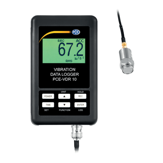
Page 7: Front Panel Description
3. FRONT PANEL DESCRIPTION Fig. 1 3-1 Display 3-12 Battery cover/Battery compartment 3-2 Power button ( Backlight button ) 3-13 Screw of the battery cover 3-14 Hanging unit ( with sticker ) 3-3 ▲ Button ( Unit Button ) 3-4 REC Button ( HOLD Button ) 3-15 Reset Button 3-5 SET Button ( Time Button ) 3-16 RS-232 Output Terminal... -
Page 8: Measuring Procedure
4. MEASURING PROCEDURE 1) Power supply installation : * The meter's power supply should install the batteries and connect " AC to DC adapter " together. * The batteries are the power of " Clock ". Batteries Install the batteries into the battery compartment : * Loose the "... - Page 9 3) Vibration unit The currently selected unit of measure is shown on the meter’s LCD. To change the unit of measure, press and hold the ▲ Button " Unit Button ( 3-3, Fig. 1 )" until the desired unit of measure appears and then release the button. if want change metric or imperial please refer chapter 7-7 (page 18 ).
- Page 10 5) Data Hold: To freeze a displayed reading on the LCD, momentarily press the"HOLD button ( 3-4, Fig. 1 )" (the HOLD icon will appear above the reading). To exit HOLD, press the HOLD button again. 6) ZERO Adjustment The ZERO function is used to remove any small offset caused by temperature changes or other environmental changes.
-
Page 11: Datalogger
8) Time check : Press the "Time button ( 3-5, Fig. 1 )" once,display will be show Year/Month/Date, Hour/Minute/ Second and samling time information. 9) 4-20 mA output : connect anather mA meter in to the viberation data recorder (3-18 Fig. 4-20 mA Output Terminal) socket,At this time the viberation data recorder will be output 4 - 20 mA analog signal ( display show 0 = 4.00mA out, show full scale = 20.00 mA out). - Page 12 c. Time setting If the meter is used at first time, it should to adjust the clock time exactly, please refer chapter 7-1 ( page 15 ). d. Decimal format setting The numerical data structure of SD card is default used the " . " as the decimal, for example "20.6"...
-
Page 13: Datalogger
* If the Display show : It means that the SD card is not plugged into the meter. SD CARD EMPTY 5-2 Datalogger a. Start the datalogger Press the " Logger button ( 3-7, Fig. 1 ) > 2 seconds continuously, until the Display show the indicator "... -
Page 14: Check Time Information
5-3 Check time information Press " Time button " ( 3-5, Fig. 1 ) > 2 seconds continuously, the LCD display will present the time information of Year/Month/Date, Hour/Minute/Second and the sampling value. 5-4 SD Card Data structure 1) When the SD card is used into the meter, the SD card When the first time, the SD card is used into the meter, the SD card will generate a folder : VBC01... -
Page 15: Saving Data From The Sd Card To The Computer
6. Saving data from the SD card to the computer ( EXCEL software ) 1) After execute the Data Logger function, take away the SD card out from the " SD card socket " ( 3-17, Fig. 1 ). 2) Plug in the SD card into the Computer's SD card slot ( if your computer build in this installation ) or insert the SD card into the "... -
Page 16: Advanced Setting
EXCEL graphic screen ( for example ) 7. ADVANCED SETTING Under do not execute the Datalogger function, press the " SET button " ( 3-5, Fig. 1 ) > 2 seconds continuously will enter the " Setting " mode., then release the " SET button ". Following press the "... -
Page 17: Set Clock Time
Remark : During execute the " Setting " function, if within 5 seconds , do not press any buttons further, the LCD Display will return to normal screen. 7-1 Set clock time ( Year/Month/Date, Hour/Minute/ Second ) When the Display show " SET DATE " 1) Use the "... -
Page 18: Set Auto Power Off
5 seconds, 10 seconds, 30 seconds, 60 seconds,120 seconds , 300 seconds, 600 seconds,1800seconds,3600 seconds. After the desired value is set, press the " Enter Button " ( 3-7, Fig. 1 ) to save the adjusting value with default. 7-3 SET POFF ON/OFF When the Display show "... -
Page 19: Set Sd Card Decimal Character
7-5 Decimal point of SD card setting When the Display show " DEC " The numerical data structure of SD card is used the " . " as the decimal with default, for example "20.6" "1000.53" . But in certain countries ( Europe ...) is used the "... -
Page 20: Set Unit
7-6 Set UNIT When the Display show "UNIT METRIC " 1) Use the " ▲ Button " ( 3-3, Fig. 1 ) or " ▼ Button " ( 3-6, Fig. 1 ) to select the upper Display text to METRIC or IMPERIAL 2) press the "... -
Page 21: Power Supply From Dc Adapter
8. POWER SUPPLY from DC ADAPTER The meter also can supply the power supply from the DC 9V Power Adapter. Insert the plug of Power Adapter into " DC 9V Power Adapter Input Socket " ( 3-9, Fig. 1 ). 9. -
Page 22: Rs232 Pc Serial Interface
11. RS232 PC SERIAL INTERFACE The instrument has RS232 PC serial interface via a 3.5 mm terminal ( 3-16, Fig. 1 ) . The data output is a 16 digit stream which can be utilized for user's specific application. Remark: * When power use AC/DC adapter , the RS-232 signal will output A RS232 lead with the following connection will be required to link the instrument with the PC serial port. - Page 23 Each digit indicates the following status : End Word D1 & D8 Display reading, D1 = LSD, D8 = MSD For example : If the display reading is 1234, then D8 to D1 is : 00001234 Decimal Point(DP), position from right to the left 0 = No DP, 1= 1 DP, 2 = 2 DP, 3 = 3 DP Polarity...
Need help?
Do you have a question about the PCE-VDR 10 and is the answer not in the manual?
Questions and answers