Table of Contents
Advertisement
Quick Links
Data Logger
PCE-THB 40
OPERATION MANUAL
PCE Americas Inc.
711 Commerce Way
Suite 8
Jupiter
FL-33458
USA
From outside US: +1
Tel: (561) 320-9162
Fax: (561) 320-9176
info@pce-americas.com
www.pce-instruments.com/english
www.pce-instruments.com
Your purchase of this
HUMIDITY/BAROMETER/
TEMP.
MONITOR
S D
DATALOGGER marks a
step
forward
into
the
precision measurement.
A l t h o u g h
DATALOGGER
complex
and
instrument, its durable
structure
many years of use if
p r o p e r
t e c h n i q u e s
developed. Please read
t h e
f o l l o w i n g
instructions
and always keep this
manual
within
reach.
PCE Instruments UK Ltd.
Units 12/13
Southpoint Business Park
Ensign way
Hampshire / Southampton
United Kingdom, SO31 4RF
From outside UK: +44
Tel: (0) 2380 98703 0
Fax: (0) 2380 98703 9
info@pce-instruments.com
with
C A R D
for
you
field
of
t h i s
is
a
delicate
will
allow
o p e r a t i n g
a r e
carefully
easy
Advertisement
Table of Contents

Subscribe to Our Youtube Channel
Related Manuals for PCE Instruments PCE-THB 40


Summary of Contents for PCE Instruments PCE-THB 40
- Page 1 Data Logger PCE-THB 40 PCE Americas Inc. PCE Instruments UK Ltd. 711 Commerce Way Units 12/13 Suite 8 Southpoint Business Park Jupiter Ensign way FL-33458 Hampshire / Southampton United Kingdom, SO31 4RF From outside US: +1 From outside UK: +44...
-
Page 2: Table Of Contents
TABLE OF CONTENTS 1. FEATURES................2. SPECIFICATIONS................ 3. FRONT PANEL DESCRIPTION..............3-1 Display..................3-2 Logger button, Enter button..............▲ button, Time button............▼ button................3-5 SET button..................3-6 Humidity/Temp./Barometer sensor..........3-7 Hanging holes................3-8 Stand................ 3-9 Battery cover/Battery compartment............3-10 Screw for battery cover............. 3-11 Reset button................ -
Page 3: Features
1. FEATURES * Monitor with real time data logger, save the measuring data along the time information ( year, month, date, hou, minute, second ) into the SD memory card and can be down load to the Excel, extra software is no need. user can make the further data or graphic analysis by themselves. - Page 4 Datalogger 5/10/30/60/120/300/600 seconds Sampling Time or Auto. * Default sampling time is 60 seconds. * The " Auto " sampling . means when the measuring value is changed ( > ℃ ± 1 %RH or > ± 1 or > ± 1 hPa ) will save the data one time only.
- Page 5 Weight 285 g/0.63 LB. Dimension 132 x 80 x 32 mm ( 5.2 x 3.1 x 1.3 inch ) Accessories Instruction manual......1 PC Included Hanging unit ( with sticker )....Optional SD Card ( 2 GB ) Accessories AC to DC 9V adapter. USB cable, USB-01.
-
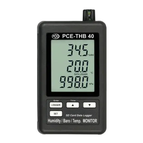
Page 6: Front Panel Description
3. FRONT PANEL DESCRIPTION Fig. 1 3-1 Display 3-2 Logger button, Enter button ▲ button, Time button ▼ button 3-5 SET button 3-6 Humidity/Temp./Barometer sensor 3-7 Hanging holes 3-8 Stand 3-9 Battery cover/Battery compartment 3-10 Screw for battery cover 3-11 Reset button 3-12 RS-232 output terminal 3-13 SD card socket 3-14 DC 9V power sdapter input socket... -
Page 7: Measuring Procedure
4. MEASURING PROCEDURE 1) Install the batteries into the battery compartment : * Loose the " Screw of the battery cover " ( 3-10, Fig. 1 ) and take away the " Battery Cover " ( 3-9, Fig. 1 ) from the meter. - Page 8 c. Time setting If the meter is used at first time, it should to adjust the clock time exactly, please refer chapter 7-2 ( page 11 ). d. Decimal format setting The numerical data structure of SD card is default used the " . " as the decimal, for example "20.6"...
-
Page 9: Datalogger
5-2 Datalogger a. Start the datalogger Press the " Logger button ( 3-2, Fig. 1 ) > 2 seconds continuously, until the Display show the indicator " DATALOGGER ", release the " Logger Button " ( 3-2, Fig. 1 ), then the measuring data along the time information will be saved into the memory circuit. -
Page 10: Sd Card Data Structure
5-4 SD Card Data structure 1) When the SD card is used into the meter, the SD card When the first time, the SD card is used into the meter, the SD card will generate a folder : HBA01 2) If the first time to execute the Datalogger, under the route HBA01\, will generate a new file name HBA01001.XLS. -
Page 11: Saving Data From The Sd Card To The Computer
6. Saving data from the SD card to the computer ( EXCEL software ) 1) After execute the Data Logger function, take away the SD card out from the " SD card socket " ( 3-13, Fig. 1 ). 2) Plug in the SD card into the Computer's SD card slot ( if your computer build in this installation ) or insert the SD card into the "... -
Page 12: Advanced Setting
EXCEL graphic screen ( for example ) 7. ADVANCED SETTING Under do not execute the Datalogger function, press the " SET button " ( 3-5, Fig. 1 ) > 2 seconds continuously will enter the " Setting " mode., then release the " SET button ". Following press the "... -
Page 13: Sd Memory Card Format
Remark : During execute the " Setting " function, if within 5 seconds , do not press any buttons further, the LCD Display will return to normal screen. 7-1 SD memory card Format When the Display show " Sd F " ▲... -
Page 14: Set Sampling Time
Remark : The adjusted unit will be flashed. 2) After set all the time value ( Year, Month, Date, Hour, Minute, Second ), press the " SET button " ( 3-5, Fig. 1 ) once will save the time value, then the screen will jump to Sampling time "... - Page 15 yES - Meter's beep sound will be ON with default when save each data. no - Meter's beep sound will be OFF with default. when save each data. 2) After select the upper text to " yES " or " no ", press the "...
-
Page 16: Set Rs232 Data Output On/Off 1
℃ ℉ 7-6 Select the Temp. unit to When the Display show " t-CF " ▲ ▼ 1) Use the " Button " ( 3-3, Fig. 1 ) or " Button " ( 3-4, Fig. 1 ) to select the upper Display text to " C " or "... -
Page 17: Set The Unit Of Barometer
7-8 Set the unit of Barometer When the Display show " bAro " ▲ ▼ 1) Use the " Button " ( 3-3, Fig. 1 ) or " Button " ( 3-4, Fig. 1 ) to select the upper Display text to hPA ", "... -
Page 18: Battery Replacement
9. BATTERY REPLACEMENT 1) When the left corner of LCD display show " ", it is necessary to replace the battery. However, in-spec. measurement may still be made for several hours after low battery indicator appears before the instrument become inaccurate. 2) Loose the "... -
Page 19: Rs232 Pc Serial Interface
11. RS232 PC SERIAL INTERFACE The instrument has RS232 PC serial interface via a 3.5 mm terminal ( 3-12, Fig. 1 ) if the RS232 function already select to " ON ", refer to chapter 7-7, page 14. The data output is a 16 digit stream which can be utilized for user's specific application. - Page 20 Decimal Point(DP), position from right to the left 0 = No DP, 1= 1 DP, 2 = 2 DP, 3 = 3 DP Polarity 0 = Positive 1 = Negative D11 & D12 Annunciator for Display ℃ ℉ = 01 = 02 % RH = 04 hPa = 91...
Need help?
Do you have a question about the PCE-THB 40 and is the answer not in the manual?
Questions and answers