Sign In
Upload
Download
Table of Contents
Contents
Add to my manuals
Delete from my manuals
Share
URL of this page:
HTML Link:
Bookmark this page
Add
Manual will be automatically added to "My Manuals"
Print this page
×
Bookmark added
×
Added to my manuals
Manuals
Brands
Blackbox Manuals
Switch
LIE1014A
Quick start manual
Blackbox LIE1014A Quick Start Manual
Industrial poe switch
Hide thumbs
1
2
3
4
5
6
7
8
9
10
11
12
Table Of Contents
13
page
of
13
Go
/
13
Contents
Table of Contents
Bookmarks
Table of Contents
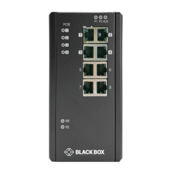
STEP 1 - Hardware Description
STEP 2 - What's Included
Ethernet Switch
Step 5 - Connect the Power
Alarm Relay and Ground
STEP 6 - Connect the Console Port
Console Connection
Connect to the Ethernet Port
STEP 8 - CLI Initialization and Configuration (Optional)
Command Line Interface (Cli)
Advertisement
Quick Links
Download this manual
STEP X - Name of Step
QUICK START GUIDE
LIE1014A, LIE1080A, LIE1082A
INDUSTRIAL
POE SWITCH
24/7 TECHNICAL SUPPORT AT 877.877.2269 OR VISIT BLACKBOX.COM
Table of
Contents
Previous
Page
Next
Page
1
2
3
4
5
Advertisement
Table of Contents
Need help?
Do you have a question about the LIE1014A and is the answer not in the manual?
Ask a question
Questions and answers
Related Manuals for Blackbox LIE1014A
Switch Blackbox LGB1108A Quick Start Manual
10-, 26-, or 48-port gigabit managed switch (36 pages)
Switch Blackbox LB620C User Manual
8-port fast ethernet tp/fiber tp/sc/scs/st/bs series module (2 pages)
Switch Blackbox LPH1006A Quick Start Manual
Lph1000 series industrial ethernet poe switch (2 pages)
Switch Blackbox LIG1014A Quick Start Manual
Industrial switch (13 pages)
Switch Blackbox LIG1082A Quick Start Manual
Industrial switch (13 pages)
Switch Blackbox LGB1003A-R2 User Manual
(1 page)
Switch Blackbox LIG401A Quick Start Manual
Industrial gigabit ethernet switches lig401a has (4) rj-45 and (1) sfp ports. lie401a has (4) rj-45 poe+ and (1) sfp ports. (2 pages)
Switch Blackbox LPH008A-R2 Quick Start Manual
Gb poe plus switch (6 pages)
Switch Blackbox LPJ008A-T-R2 User Manual
8- or 16-port 10 / 100 / 1000 poe injector (12 pages)
Switch Blackbox LPJ016A-T-R2 User Manual
8- or 16-port 10 / 100 / 1000 poe injector (12 pages)
Switch Blackbox LIE1082A Quick Start Manual
Industrial poe switch (13 pages)
Switch Blackbox ServSwitch SW625A-R2 User Manual
Kvm switch (24 pages)
Switch Blackbox KV2004A User Manual
Servswitch wizard dvi dl (37 pages)
Switch Blackbox KV7118SA User Manual
Servswitch elite (72 pages)
Switch Blackbox SERVSWITCH Series Manual
(71 pages)
Switch Blackbox ACX1004 SERIES User Manual
Dkm tc km switch w/ hid ports (36 pages)
This manual is also suitable for:
Lie1080a
Lie1082a
Table of Contents
Print
Rename the bookmark
Delete bookmark?
Delete from my manuals?
Login
Sign In
OR
Sign in with Facebook
Sign in with Google
Upload manual
Upload from disk
Upload from URL


Need help?
Do you have a question about the LIE1014A and is the answer not in the manual?
Questions and answers