Table of Contents
Advertisement
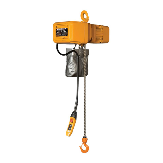
ER2 Series Electric Chain Hoist
To Customer
• Thank you for purchasing KITO Electric Hoist (ER2).
• Operators and maintenance engineers are requested to read this manual.
After reading, please keep this manual at hand for future use.
• This product is designed considering the environment protection. The product contains none of six hazardous
substances specified by European RoHS Directives nor asbestos.
Original Instruction
Owner's Manual
Hook Suspended Type (hoist only) : ER2
Motorized Trolley Type : ER2M
Manual Trolley Type : ER2SP/ER2SG
OM-ER2ZZZ-CEE-02
(125kg to 5t)
Advertisement
Chapters
Table of Contents
Troubleshooting

Related Manuals for KITO ER2M


Summary of Contents for KITO ER2M
- Page 1 Motorized Trolley Type : ER2M Manual Trolley Type : ER2SP/ER2SG To Customer • Thank you for purchasing KITO Electric Hoist (ER2). • Operators and maintenance engineers are requested to read this manual. After reading, please keep this manual at hand for future use.
- Page 2 KITO shall not be liable for any incidental damage due to the use or non-use of the product such as the loss ●...
- Page 3 ■ Restriction on Use The product described herein is not designed or manufactured for transporting people. Do not use the ● product for that purpose. The product described herein is designed for the materials handling work such as lifting/lowering and ●...
- Page 4 Safety Precautions Improper use of electric chain hoist causes danger such as drop of lifted load. Read this Owner’s Manual carefully before installation, operation and maintenance. Use the product after understanding the product knowledge, safety information and precautions. This Owner’s Manual classifies the safety information and precautions into three categories of “DANGER”, “WARNING”...
- Page 5 Mandatory Refer to “Disassembly/Assembly Manual” for disassembling, or contact KITO. (This product uses oil. We prepare SDS (Safety Data Sheet) for the oil. Contact KITO for it.) • Carry out daily inspection by user. • Carry out inspection (monthly, annual) by maintenance engineer.
-
Page 7: Table Of Contents
Chapter 1 Handling the Product This chapter describes mainly how to use, assemble and install, and the check after installation. It also describes the daily inspection items before use. ● For Operators and Maintenance Engineers Type and Names of Each Part ............8 Opening the Package ..............11 Product Specification and Operational Environment ....16 How to Use ..................19... -
Page 8: Type And Names Of Each Part
Chapter 1 Handling the Product Type and Names of Each Part ■ Hook Suspended Type (ER2) Electric chain hoist dedicated for elevation ● Top Hook Body Electric Chain hoist name plate Chain Container Load Chain Cushion Rubber (Chain spring and end plate for the Push Button model of rated load 2 t or more) Switch Cord... - Page 9 ■ Motorized Trolley Type (ER2M) Electric Chain Hoist combined with motorized trolley (MR2) for elevation and traveling motion ● Motorized trolley nameplate Connection Box Cable Support Bar Relay Cable Power Cable Electric chain hoist nameplate Chain Container Push Button Load Chain...
- Page 10 Chapter 1 Handling the Product Type and Names of Each Part (continued) ■ Manual Trolley Type (ER2SG/ER2SP) ER2SG : The electric chain hoist equipped with the geared trolley (TSG) enabling fine ● adjustable lateral motion of the load by pulling the hand chain. ER2SP : The electric chain hoist equipped with the plain trolley (TSP) enabling lateral motion by moving the ●...
-
Page 11: Opening The Package
Equipped with 5-Push Power * Suspender Button Cable Switch set Model MR2 Motorized Trolley ER2M Crane 7-Push Power * Control Box Button Cable Switch set * Power Cable longer than 10 m is available as an optional part. ■ Parts packaged with the Electric Chain Hoist... - Page 12 Chapter 1 Handling the Product Opening the Package (continued) ■ Nameplate and Product Model ■ Nameplate Indication of Electric Chain Hoist Y A MA N A S H I 4 0 9 3 8 5 3 P A N ① ③...
- Page 13 ■ Nameplate Indication of Motorized Trolley Y A MA N A S H I 9 3 8 5 3 P A N ① ② ④ C ODE ( K E NN- NR. ) : : ) . R ⑤ T RAVE LI NG S PE E D (F AHRGE S CHW DIGKEI T) : S E RIAL No.( S E RI E NNR.): ⑥...
- Page 14 Chapter 1 Handling the Product Opening the Package (continued) ■ Nameplate Indication of Manual Trolley KENN-NR./CODE:TSG010 ④ BJ./MFG.YEAR LIEFERNR./LOT No.TS2- ② ③ SERIENNR./SERIAL No. TRAGF. ① YAMANASHI 409-3853 JAPAN MADE IN JAPAN · · · Capacity Ex. 1t, 500kg The maximum mass of the load that can be imposed on the product. The mass of the hook is excluded. 2 LOT No.
- Page 15 RH-DAT ER2-020L/IL 10.2 16 Links Front side : RH-DAT Front side : Original Lot No. of the ER2-020S/IS Load Chain (4 digits) FT-DAT Back side : KITO ER2-025S/IS 11.2 12 Links Back side : H23 ER2-032S/IS 10.2 16 Links ER2-050S/IS 11.2...
-
Page 16: Product Specification And Operational Environment
7-Push Button Switch set for motorized trolley combined model Power supply method..Power supply through cabtyre cable Color.......KITO Yellow (Equivalent to Munsell 7.2YR6.5/14.5) Noise level : ER2, single speed 75dB or less (A scale: measured at 1 m away from the Electric chain hoist) - Page 17 ● ISO 4301 specifies the total operating hour (service life) of gears and bearings according to the loading status. For example, the total operating hour (service life) of the mechanism when it is constantly applied with the capacity is 1,600 hours for M5. The total operating hour is 6,300 hours when operated with a medium load. Total operating hour h Loading status* 1600...
- Page 18 Chapter 1 Handling the Product Product Specification and Operational Environment (continued) ■ Operational Environment Ambient temperature : -20°C — +40°C Gradient of rail : No gradient in travel rail (for the hoist with trolley) Ambient humidity : 85 % or less (no condensation) Explosion-proof construction : Not applicable to the work environment with explosive gases or explosive vapor Non-conforming environment : A place with organic solvent or volatile powder, and a place with a plenty of powder and dust of general substances...
-
Page 19: How To Use
How to Use ER2 Series Electric Chain Hoist has two models: single speed model and dual speed VFD model. Other than them, such products are provided that can travel/traverse when combined with a trolley or a crane. Their push button switches for operation differ in the size and the operating method. -
Page 20: Daily Inspection Of Electric Chain Hoist (Hook Suspended Type)
When replacing with a new nameplate or label is required, please inform KITO of the description in “Record of the Product No." (P17) such as Lot No. and Serial No. Deformation • Check visually. - Page 21 ■ Load Chain Item Check method Criteria When failed Elongation of • Check visually • No apparent elongation Refer to Load Chain Pitch (P69) of Chapter 2, Frequent inspection. Abrasion • Check visually • No apparent abrasion Refer to Load Chain of Wire (P69) of Chapter 2, Diameter...
- Page 22 Chapter 1 Handling the Product How to use (continued) ■ Top Hook/Bottom Hook Item Check method Criteria When failed Opening of • Check visually • No apparent opening of the Hook Carry out the the Hook inspection item of Top and Bottom Hook (P70) of Frequent inspection.
- Page 23 Item Check method Criteria When failed Movement • Check the Idle Sheave by Replace the bearing of CAUTION of the Idle moving the Idle Sheave. • When checking, wear gloves Sheave and be careful for your finger not to be caught. Mandatory Otherwise it may result in injury.
- Page 24 Chapter 1 Handling the Product How to use (continued) ■ Push Button Switch Item Check method Criteria When failed Switch body • Check visually • No deformation, damage and no loosened Clean and repair the size screw label or replace with • Label indication of the push button switch can a new label.
-
Page 25: Daily Inspection Of Motorized Trolley (Mr2)
■ Daily Inspection of Motorized Trolley (MR2) ■ Appearance Item Check method Criteria When failed Indication of • Check visually • No peel off. Indication can be seen clearly. Clean and repair the Nameplates label or replace with a and Labels new label. -
Page 26: Daily Inspection Of Manual Trolley (Tsg/Tsp)
Chapter 1 Handling the Product How to use (continued) ■ Function and Performance ● Check the following item with no load. Item Check method Criteria When failed Operational • Press the push button to • To travel smoothly. No meandering and Refer to Chapter 2 vibration. - Page 27 ■ Function and Performance ● Check the following item with no load. Item Check method Criteria When failed Operational • Check the traveling motion • To travel smoothly. No meandering and Carry out Chapter 2 Check of the electric chain hoist by vibration.
-
Page 28: How To Operate The Push Button Switches
Chapter 1 Handling the Product How to use (continued) ■ How to Operate the Push Button Switches CAUTION • Do not hang the Push Button Switch Cord on other object, or pull the cord strongly. • Do not use the Push Button Switch if its button does not operate smoothly. •... - Page 29 ■ 5-Push Button Switch Set 5-Push Button Switch Set is equipped with a lock type emergency stop button (VFD reset button) and lift/lower push buttons. One-step push button switch or two-step push button switch is mounted as Lift/lower push button switches in accordance with the specification of single speed or dual speed VFD specification.
- Page 30 Chapter 1 Handling the Product How to use (continued) ■ 7-Push Button Switch Set 7-Push Button Switch Set is equipped with a lock type emergency stop button (VFD reset button) and lift/lower push buttons. One-step push button switch or two-step push button switch is mounted as Lift/lower push button switches in accordance with the specification of single speed or dual speed VFD specification.
-
Page 31: Operation
■ Operation ■ General DANGER • Do not operate the electric chain hoist in an environment with flammable or explosive gas. The electric chain hoist is not designed as explosion proof specification. Prohibited • Do not use the electric chain hoist exceeding the ratings (short period rating, intermittent rating) of the lifting motor and the maximum start-up frequency. - Page 32 Chapter 1 Handling the Product How to use (continued) ■ Lifting/Lowering DANGER • Do not lift more than the capacity. (Fig. E) The capacity is indicated in the nameplate. • Do not operate the electric chain hoist exceeding the lifting height. Prohibited •...
- Page 33 CAUTION • Do not use the Friction Clutch to measure the weight of a load. The use of the Friction Clutch other than intended purpose may result in injury or property damage. Prohibited • When carrying a lifted load using a lifting magnet or a vacuum chuck, lower the height of the lifted load as low as possible.
-
Page 34: Speed Change Of Dual Speed Vfd Model
Wrong parameter settings may result in danger such as defective operation and drop of lifted load. Contact Please Prohibited contact KITO for consultation. Failure to comply with these instructions may result in death or serious injury. • When changing the parameter, set it correctly referring to the VFD Manual. -
Page 35: Precautions After Work
■ Precautions After Work CAUTION • Do not store the electric chain hoist at a state of over lifting or over lowering. Failure to comply with these instructions causes bodily injury or loss of property. Prohibited • Store the electric chain hoist with power off. •... -
Page 36: Work Flow Of Assembling And Installation
Hook Suspended Type (hoist only) Trolley Type Motorized Trolley Type Manual Trolley Type ER2M ER2SG / ER2SP Assembling Parts to Electric Chain Hoist (P37) How to use the Oil Cap Preparation... -
Page 37: Assembling
Assembling DANGER • Only maintenance engineers or the personnel with expertise are allowed to assemble and disassemble the electric chain hoist. Assembling or disassembling of the electric chain hoist may result in death or serious injury. Prohibited ■ Assembling Parts to Electric Chain Hoist ■... - Page 38 Chapter 1 Chapter 1 Handling the Product Handling the Product Assembling (continued) Chain Container Seal ● A seal in the right to indicate the relation between the size of the Load Chain and the lift is attached to the Chain Container. Be sure to check it before installation.
- Page 39 Case without Chain Container ● When using the electric chain hoist without the Chain Container, take the following measures. 1) Mount the Stopper at the no-load side of Body size ER2-B/C/D/E the Load Chain. * Number of Links between Chain End Suspender and the Stopper Body size Number of Links...
- Page 40 Chapter 1 Handling the Product Assembling (continued) ■ Oiling the Load Chain DANGER • Be sure to apply lubricant on the Load Chain. Do not carry out oiling work in the place near the fire or arc. Otherwise it will result in fire. Mandatory Remove dust and waterdrops attached on the Load Chain and then apply lubricant.
-
Page 41: Combination With The Trolley
■ How to Use the Oil Cap (only for the Friction Clutch with mechanical brake) An Oil Cap is packaged along with the electric chain hoist equipped with built-in Friction Clutch with mechanical brake (option). When installing the hoist, remove the oil plug and attach the Oil Cap instead. When combining the motorized trolley, mount the oil cap to the hoist at a position where the Oil Cap and the frame of the Trolley do not interfere. - Page 42 ■Combining with the Motorized Trolley CAUTION • When using ER2 series electric chain hoist combined with our old type product, specification needs to be changed. Contact your nearest dealer or KITO. Prohibited ■ Parts replacement of the electric chain hoist The Suspender is attached to the electric chain hoist at shipping.
- Page 43 ■ Checking the Number of the Assembled Adjusting Spacers and Their Positions When installing a trolley to the beam, the length of the Suspension Shaft (width between frames) must be adjusted in accordance with the rail width. Wrong number of wrong position of Spacers may result in the drop of the electric chain hoist. Insert the correct number of Spacers with correct ratings and for rail width at the correct position, referring to the following table.
- Page 44 Chapter 1 Handling the Product Assembling (continued) Adjusting spacer arrangement for LOW Head Suspension (Beam flange width 155-305mm) ● Beam flange width (mm) Parts Name Inner 5 Thin spacer Outer 125kg Inner 2 Thick spacer 250kg Outer 500kg Inner 0 Fixing spacer Outer Inner 1...
- Page 45 Adjusting spacer arrangement for Lug Suspension ● Number of Adjusting Spacers Beam flange (in) 2 width (mm) 58 98 100 102 106 110 113 125 127 131 135 137 143 153 155 160 163 170 Parts Name 0 1+0 1+1 1+2 2+2 3+3 0 1+0 1+1 3+3 4+0 4+1 1+1 2+2 2+3 3+0 Thin spacer Thick spacer...
- Page 46 Chapter 1 Handling the Product Assembling (continued) ■ Combination of the Electric Chain Hoist and the Motorized Trolley DANGER • Use new split pins. After insertion, bend the pin securely at its both ends. Use of old split pins may result in death or serious injury due to drop. Mandatory 125 kg~5 t ●...
- Page 47 ■Combination with the Manual Trolley ■Parts replacement of the Electric Chain Hoist Manual Trolley For Double Chain Type Remove the Top Hook and replace it with a Connection Yoke. Replacing the Top Hook of Body size ER2-B/C/D/E ● 1) Remove the Shaft Retainer Clip using plier.
- Page 48 Chapter 1 Handling the Product Assembling (continued) ■ Checking the Number of the Assembled Adjusting Spacers and Their Positions When installing a trolley to the beam, the length of the Suspension Shaft (width between frames) must be adjusted in accordance with the rail width. Wrong number of wrong position of Spacers may result in the drop of the electric chain hoist.
- Page 49 Capacity(t) Beam flange width (mm) Parts Plain Geared Name trolley trolley Inner 2 3 3 4 4 5 0 0 1 1 2 2 0 1 1 1 1 2 2 2 4 4 3 3 2 2 1 2 4 5 2 5 Thin spacer Outer 125kg...
- Page 50 Chapter 1 Handling the Product Assembling (continued) ■ Combination of the Electric Chain Hoist and the Manual Trolley DANGER • Use new split pins. After insertion, bend the pin securely at its both ends. Use of old split pins may result in death or serious injury due to drop. Mandatory 125 kg~2.5 t ●...
- Page 51 3 t~5 t (For Double Chain type) ● Split pin 1) Fix the Suspension Shaft to the Frame G or the Frame S with a Suspension Shaft Frame S Bolt, a slotted nut and a split pin. • When fixing the Frame G or the Frame S to the Frame G Suspension Shaft, use the hole for standard rail Split pin...
-
Page 52: Checking Power And Power Cable
ER2-005L/IL ER2-003H/IH ER2-005S/IS 1.25 ER2-010L/IL ER2-010S/IS ER2-016S/IS ER2-020L/IL ER2-020S/IS ER2-025S/IS ER2-032S/IS ER2-050S/IS Motorized Trolley type:ER2M ● Capacity of fuse and circuit breaker (A) Wire size 230V Class 400V Class Code ER Single ER Dual ER Single ER Dual MR Single... - Page 53 ER2-020S/IS ER2-025S/IS (3.5) (37) (32) (30) (103) (99) (93) (64) (58) ER2-032S/IS ER2-050S/IS Motorized Trolley type:ER2M ● (Unit: m) 230V Class 400V Class ER single ER dual ER dual ER single ER single ER dual ER dual ER single single...
-
Page 54: Connecting Cables
Chapter 1 Handling the Product Assembling (continued) ■ Connecting Cables NOTE • When clamping a connector, do not use tools. Be sure to clamp it by hand. Excessive tightening of a connector may result in the damage or breakage f plastic thread part. •... - Page 55 ■Motorized Trolley Type ■125 kg~5 t Connecting the relay cable Connecting the Power Cable ● ● 1) Insert the Power Cable into the Holder 1) Remove the Holder A mounted to the C (upper side) of the Socket frame. Connection Box. Turn the Holder A to connect the cable 2) Pass the Power Cable through the securely.
- Page 56 Chapter 1 Handling the Product Assembling (continued) ■Manual Trolley Type ■125 kg~5 t 1) Connecting the Power Cable Insert the Power Cable into the Holder C (upper side) of the Socket frame. Turn the Holder A to connect the cable securely.
-
Page 57: Installation
Consult with the sales shop or KITO for installation, or consign the installation work to special installer or personnel with expertise. • Do not install the electric chain hoist at a place exposed to rain or water always or the place different Prohibited from the Operational Environment (P18). -
Page 58: Installing The Trolley Combined Model
Chapter 1 Handling the Product Installation (continued) ■ Installing the Trolley Combined Model ■Mounting the Hoist to the Travel Rail 1) Make sure that the dimensions of the Sling Trolley Frame satisfy the size of the rail to which the trolley is installed. 2) Make sure that the rail is set to a level. - Page 59 ■ Mounting the Stopper Be sure to mount the stoppers at the both ends of the rail to prevent drop. Decide the mounting position in accordance to the size of the wheel. When the customer wants to make the stopper by oneself, refer to the following figures. Beam width Stopper Bolt...
- Page 60 T-shape Suspender can be applicable to curved rail, however, the application method differs depending on the condition such as radius of curvature. In such case, contact KITO. 1) Mount the wire support bar at the both Rail ends of the rail.
-
Page 61: Check After Installation
Check after Installation Wrong assembling or installation causes death or serious injury. To prevent such danger check the following. ■ Check items Make sure that the following are satisfied: • No bolt, nut nor split pin is lost. Tightening and assembling are completed. • Protection Wire for Push Button Switch Cord is securely tied to accept and endure the force instead of Push Button Switch Cord when the Push Button Switch Set is drawn. - Page 62 Chapter 1 Handling the Product...
- Page 63 Chapter 2 Inspection This chapter describes frequent inspection items and periodic inspection items. Refer to Chapter 1 for the “Handling the Product”. Inspection is the first step of safety. Carry out daily inspection, frequent inspection and periodic check. Table of Contents ................64 Safety Precautions ................66 Frequent Inspection ................68 Periodic Inspection ................75...
-
Page 64: Table Of Contents
Chapter 2 Inspection Table of Contents ■ Safety Precautions ………………………………… 66 ■Frequent Inspection ■ Periodic Inspection (Carry out the frequent inspection after check of no (Carry out the periodic inspection after check of no abnormality in daily inspection items.) abnormality in daily inspection and frequent inspection items.) ■Electric Chain Hoist (ER2) Frequent Inspection ■Electric Chain Hoist (ER2) Periodic Inspection... - Page 65 ■Motorized Trolley (MR2) Periodic Inspection Guidelines on Hook and Yoke Replacement …… 92 Guidelines on V ring Inspection ………………… 92 Brake ■ Check of Operating Hours and Number of Start Appearance ……………………………………… 84 Abrasion of Brake Pad …………………………… 84 (CH Meter) CH Meter: Start Times/Operating Hour Display Device …...
-
Page 66: Safety Precautions
Prohibited for KITO electric chain hoist. Even if the part is genuine KITO part, it cannot be used for other model. Refer to Disassembly/Assembly Manual (Annex) for the correct use of the part. • Do not adjust or disassemble the Electromagnetic Brake, the Friction Clutch and the Friction Clutch with Mechanical Brake. - Page 67 NOTE • When performing the frequent inspection, carry out the daily inspection at the same time. • When performing the periodic inspection, carry out the frequent inspection at the same time. • When detecting any abnormality during inspection due to erroneous use, instruct the operator and user for correct use of the electric chain hoist.
-
Page 68: Frequent Inspection
• Do not change the VFD parameter. When parameters need to be changed, ask our distributors nearest to the customer or KITO. • Do not carry out the work such as maintenance and inspection within 5 minutes after power off. -
Page 69: Electric Chain Hoist (Er2) Frequent Inspection
● Use the needle head caliper (point caliper) to measure the sum of pitches and wire diameter. ● Apply oil on the Load Chain after inspection. ● Application of lubricant influences on the life of the Load Chain considerably. Use the KITO genuine lubricant or equivalent (industrial lithium grease: consistency No.0) ●... -
Page 70: Top Hook, Bottom Hook
Chapter 2 Inspection Frequent Inspection (continued) ■ Top Hook, Bottom Hook Item Check method Criteria When failed Opening and • Check visually and measure Replace the Hook. CAUTION Abrasion of with vernier caliper. • Compare the dimensions the Hook Embossed mark of a, b and c with those at purchasing. -
Page 71: Peripheral Parts Of The Body Size
■ Peripheral parts of the Body size ● Use check stand to check the electric chain hoist from the close point. Item Check method Criteria When failed Chain • Check visually. • To be mounted to the body size securely Replace the Chain Container • No damage, tear, abrasion or deformation... -
Page 72: Push Button Switch
Chapter 2 Inspection Frequent Inspection (continued) ■ Push Button Switch Item Check method Criteria When failed Push Button • Check visually and by • No damage, deformation and loosened bolt. Replace the Push Switch Body operation. • Push Button Switches can be operated Button Switch. -
Page 73: Power Supply
■ Power Supply Item Check method Criteria When failed Power Cable • Check visually. • Power Cable to have enough length. Replace the Power • To have no damage Cable. • To be connected securely Cable Hanger • Check visually and by • To have no damage Re-mount the Cable moving by hand. -
Page 74: Motorized Trolley (Mr2) Frequent Inspection
Chapter 2 Inspection Frequent Inspection (continued) ■ Motorized Trolley (MR2) Frequent Inspection ■ Appearance Item Check method Criteria When failed Travel Rail • Check visually. • To have no apparent deformation and damage Check items in accordance with “Travel Rail” described in Chapter 2 “Periodic Inspection”. (P86) Oiling • Check visually. -
Page 75: Periodic Inspection
• Do not change the VFD parameters. When parameters need to be changed, ask our distributors nearest to the customer or KITO. • Do not carry out the work such as maintenance and inspection within 5 minutes after power off. -
Page 76: Electric Chain Hoist (Er2) Periodic Inspection
Chapter 2 Inspection Periodic Inspection (continued) ■ Electric Chain Hoist (ER2) Periodic Inspection ■ Top Hook, Bottom Hook Item Check method Criteria When failed Number of • Check the number of start • Number of start must not exceed the Replace the Top Hook start with the CH Meter. -
Page 77: Chain Spring
Item Check method Criteria When failed Chain Spring • Check visually and measure • Check visually to have no apparent setting Replace the Chain the dimensions. (deformation). Spring. CAUTION • T h e d efo r m at i o n of t h e Cushion Rubber and the Chain Spring is caused by excessive use of the Friction... -
Page 78: Chain Pin (Double Type Only)
Chapter 2 Inspection Periodic Inspection (continued) Item Check method Criteria When failed Chain Pin • Check visually and measure • To have no apparent deformation and flaw. Replace the Chain Pin. (double type with vernier caliper. Service Limit of Chain Pin only) (Do not fall short of the limit value.) Diameter d (mm) Code Standard... -
Page 79: Electromagnetic Brake
■ Electromagnetic Brake Item Check method Criteria When failed Appearance • Remove the Brake Cover • To have no loosened bolt and screw. Tighten bolts and and check visually. screws. • To have no flaw and damage. Replace the Electromagnetic Brake. • Measure the gap with • Electromagnetic Brake Gap Limit Replace the thickness gauge. -
Page 80: Driving Mechanism
Chapter 2 Inspection Periodic Inspection (continued) ■ Driving Mechanism Item Check method Criteria When failed Bearing • Check visually and rotate • T o have no harmful deficiency such as apparent Replace the Bearing. the Bearing by hand. abrasion, flaw and damage. To rotate smoothly. • Check the operating hours • The operating hours must not exceed with the CH Meter. -
Page 81: Ring
Item Check method Criteria When failed Abrasion and • Disassemble the Load • To have no apparent abrasion, deformation Replace the Load flaw of the Sheave and check it visually. and damage Sheave. Load Sheave • Measure the thickness with • To have neither abrasion of the sheave pocket vernier caliper. -
Page 82: Electrical Equipment
Chapter 2 Inspection Periodic Inspection (continued) ■ Electrical Equipment Item Check method Criteria When failed Electrical • Remove the Controller • To have no damaged or burnt part. Replace the damaged Parts Cover and check the • To have no loosened bolt. Electrical parts or burnt electrical part. -
Page 83: Grounding Resistance
Item Check method Criteria When failed Grounding • Measure the grounding • grounding resistance 100Ω or less Make a grounding Resistance resistance with earth- correctly. DANGER resistance meter. • Turn off the power when measuring the grounding resistance. Mandatory Measuring the grounding resistance without turning off the power may result in death or serious injury due to electric shock. - Page 84 Chapter 2 Inspection Periodic Inspection (continued) ■ Motorized Trolley (MR2) Periodic Inspection ■ Brake Item Check method Criteria When failed Appearance • Disassemble the Brake and • T o have no deformation, flaw and damage on Replace the Part. check it visually. the Brake Drum and the Motor Cover. • To have no deformation and damage on the Replace the Brake Brake Spring.
- Page 85 Item Check method Criteria When failed Lifting Shaft • Check visually. • To have no considerable deformation and Replace the Lifting • Measure the shaft diameter abrasion Shaft. with vernier caliper. • The shaft with obvious deformation reaches at the service limit. • Abrasion limit of the shaft is 5 % of its diameter Shaft diameter respectively.
- Page 86 Chapter 2 Inspection Periodic Inspection (continued) ■ Travel Rail Item Check method Criteria When failed Rail Surface • Check visually. • To have no attachment of paint, oil and foreign Clean the Travel Rail. matter. • To have no dust and powder due to abrasion Deformation • Check the deformation • T o have no deformation of beam flange such...
- Page 87 ■ Function and Performance DANGER • After completion of the inspection of each part, perform the operational check for correct operation. Neglecting to perform the operational check may result in death or serious injury. Mandatory ● Perform the following inspections with capacity. Item Check method Criteria...
- Page 88 Chapter 2 Inspection Periodic Inspection (continued) ■ Manual Trolley (TSG/TSP) Periodic Inspection ■ Body size Components Item Check method Criteria When failed Wheel • Check visually. • To have no apparent deformation and Replace the Wheel. • Measure dimensions D and damage t with vernier caliper.
- Page 89 Item Check method Criteria When failed Deformation • Check the deformation • T o have no deformation of beam flange such Replace or repair the and Abrasion and abrasion visually and as twist and shear drop Travel Rail. measure them with vernier • To have no exceeding abrasion of rail surface caliper.
-
Page 90: Guidelines For Parts Replacement Based On Indication Of Ch Meter
Gear oil amount (ml) ER2-001H, 001IH, 003S, 003IS ER2-003H, 003IH, 005L, 005IL, 005S, 005IS ER2-010L, 010IL Friction Clutch ER2-010S, 010IS KITO genuine oil KITO genuine oil ER2-016S, 016IS, 020L, 020IL 1300 ER2-020S, 020IS, 032S, 032IS 1900 ER2-025S, 025IS, 050S, 050IS... - Page 91 ■ Guidelines on Needle Bearing (for Idle Sheave) Grease Change Cycle Operating hour for gear oil change Every 200 hrs Every 400 hrs Rate of loading ○ Light A case where the capacity is rarely applied. Usually the hoist is used with a light load. A case where the capacity is applied considerably frequently.
-
Page 92: Check Of Operating Hours And Number Of Start (Ch Meter)
Chapter 2 Inspection Periodic Inspection (continued) ■ Guidelines on Motor Shaft (with Rotor) Replacement Operating hours to replace parts Every 1600 Every 3200 Every 400 hours Every 800 hours Body size grade hours hours M6, 3m – Apply grease on spline * –... - Page 93 Chapter 3 Troubleshooting This chapter describes the main failure cause and inspection items based on the fault conditions. The repair work (and maintenance work as well) of the electric chain hoist is accompanied with disassembling/assembling work. Refer to the separate “Disassembling/Assembling Manual” for the correct work. ■Guidance on Troubleshooting ............94 ■Safety Precautions ................98 ■Troubleshooting................99...
-
Page 94: Guidance On Troubleshooting
Chapter 3 Troubleshooting Guidance on Troubleshooting ■ Guidance on Troubleshooting Following table is the summary of the main failure causes based on the failure conditions and their inspection items. Refer to the page of each item for the check method, treatment and the details of countermeasure. • Refer to “Technical Materials”... - Page 95 Main fault Reference Conditions Check item contents page Abnormal Popping sound Abrasion of the Load Load Chain noise Chain Abrasion of the Load Load Sheave, Idle Sheave Sheave Sounds strange operating sound Abrasion or breakage of Gears and Joints Gear Deterioration of Bearing Bearing Brake noise...
- Page 96 Chapter 3 Troubleshooting Guidance on Troubleshooting (continued) ■ Dual Speed VFD Model Main fault Reference Conditions Check item contents page Unable to restart the VFD by resetting with emergency stop Those related to VFD Check the error code of “VFD (the case when the VFD cannot be reset even after cool down) VFD referring to “VFD Manual”...
- Page 97 Main fault Reference Conditions Check item contents page Does not stop Too long stopping distance Relay failure or melted Relay normally. contact point Too long (or short) stopping distance Abrasion of brake lining Brake Does not stop at the upper/lower limit. Negative phase connection Power Cable of motor lead wires...
-
Page 98: Safety Precautions
• When replacing the part, be sure to use the genuine part for KITO electric chain hoist ER2, ER2M, ER2SP and ER2SG. Even if the part is the KITO genuine part, the part for different model may not be used. Use the correct part in accordance with separate “Disassembling/Assembling Manual”. -
Page 99: Troubleshooting
Troubleshooting Power Symptom Cause Remedy Main factor Countermeasure Electric chain hoist Improper source Measure the voltage of each phase at Faulty power receiving Check the power does not operate. voltage power receiving terminal. facility receiving facility If the source voltage is improper, check regularly. -
Page 100: Power Cable
Chapter 3 Troubleshooting Troubleshooting (continued) Power Cable Symptom Cause Remedy Main factor Countermeasure Electric chain hoist Wire breakage Check the conduction, flaw, crimping of Excessive force Support the cable with does not operate. (more than two terminals and soldering of plug. applied on the cable Cable Support Arm wires) -
Page 101: Motor
Motor Symptom Cause Remedy Main factor Countermeasure Motor does not Motor coil burning Measure the coil resistance of each Over current due to Operate the electric operate. (two or more phase. Replace the motor when the over voltage or low chain hoist at the rated phases) resistance of all phases are infinity. -
Page 102: Brake
Chapter 3 Troubleshooting Troubleshooting (continued) Brake DANGER • Do not adjust/disassemble the Electromagnetic Brake. Adjusting or disassembling the Electromagnetic Brake may result in death or serious injury. Prohibited Symptom Cause Remedy Main factor Countermeasure Electromagnetic Brake coil burning Measure the coil resistance of the Brake Over current due to Operate the electric Brake does not... - Page 103 Symptom Cause Remedy Main factor Countermeasure Electromagnetic Rusting When the Brake is rusted shut, replace Wrong assembling of Assemble the brake Brake does not the brake unit as a whole. packings cover packings and V operate. ring securely. Replace the packing if deteriorated.
-
Page 104: Internal Wiring
Chapter 3 Troubleshooting Troubleshooting (continued) Internal wiring Symptom Cause Remedy Main factor Countermeasure Electric chain hoist Breakage of wire Check the wire. Repair the wire if broken. Vibration, impact Use the electric chain does not operate. hoist avoiding the impact. Lead wire damaged at Be careful not to have assembling... -
Page 105: Electromagnetic Contactor, Relay
Electromagnetic Contactor, Relay Symptom Cause Remedy Main factor Countermeasure Electric chain hoist Electromagnetic Operate the contactor manually to check Excessive inching or Do not perform does not stop Contact point the conduction. plugging operation excessive operation. welding, or fusing When the contact point is welded or (consecutive fused, replace the contactor. -
Page 106: Upper/Lower Limit Switch
Chapter 3 Troubleshooting Troubleshooting (continued) Upper/Lower Limit Switch Symptom Cause Remedy Main factor Countermeasure Electric chain hoist Contact point fusing Actuate the limit switch manually to Habitual use of the limit Do not use the limit does not operate. check the conduction of the contact switch switch habitually. -
Page 107: Push Button Switch
Push Button Switch Symptom Cause Remedy Main factor Countermeasure Electric chain hoist Emergency Stop When the Emergency Stop button is Forgot releasing the Read “How to operate does not operate. button is pressed to Emergency Stop the push button” (P28) pressed and locked, turn it clockwise to (Electromagnetic its end and locked. -
Page 108: Vfd
Chapter 3 Troubleshooting Troubleshooting (continued) Symptom Cause Remedy Main factor Countermeasure Electric chain hoist VFD failure Reset the VFD by pressing Emergency VFD failure Check the error code does not operate. Stop button. It the VFD still does not indicated by VFD operate, check it. -
Page 109: Electric Shock
(The gear oil for Friction Clutch with Mechanical Brake is different from the standard specification oil.) Mandatory Use of the oil other than KITO genuine oil may result in death or serious injury due to the drop of a lifted load. Leaving the electric... -
Page 110: Friction Clutch With Mechanical Brake
Mechanical Brake Mandatory is dif ferent from the standard specification oil.) Use of the oil other than KITO genuine oil may result in death or serious injury due to the drop of a lifted load. Secular change Leaving the electric... -
Page 111: Hook
Hook Symptom Cause Remedy Main factor Countermeasure Widened Hook Deformation of the Replace the Hook if the deformation Over load Use the electric chain opening Hook exceeds the criteria. (See P70.) hoist with a load less than the capacity. Earth lifting Do not carry out earth lifting. - Page 112 Chapter 3 Troubleshooting Troubleshooting (continued) Hook (continued) Symptom Cause Remedy Main factor Countermeasure Hook Latch has Deformation of the Replace the Hook if the deformation Over load Use the electric chain come off Hook exceeds the criteria. (See P70.) hoist with a load less than the capacity.
-
Page 113: Load Chain
Load Chain Symptom Cause Remedy Main factor Countermeasure Twisted Load Chain Capsized Bottom Turn over the Bottom Hook to the original Bottom Hook was When using multi fall Hook position to cancel the capsizing. turned over by one turn model hoist, check during working. - Page 114 Store the electric chain hoist exposed to rain hoist indoor or under the roof when not using. Influence of sea water Contact KITO for and chemicals the use in special environment in advance. Use the electric chain hoist correctly within the scope guaranteed by the manufacturer.
-
Page 115: Load Sheave, Idle Sheave
Mechanical Brake Mandatory is dif ferent from the standard specification oil.) Use of the oil other than KITO genuine oil may result in death or serious injury due to the drop of a lifted load. Long hour operation Apply grease at without grease (motor periodic inspection. -
Page 116: Bearing
Chapter 3 Troubleshooting Troubleshooting (continued) Bearing Symptom Cause Remedy Main factor Countermeasure Unable to lift a load. Sticking, Breakage Replace the bearing. Use under hot Avoid using under environment or hot environment or excessively frequent use excessively frequent use Strange noise Deterioration Replace the bearing. - Page 117 Traveling motion of the Trolley (only for motorized trolley) Symptom Cause Remedy Main factor Countermeasure Wheel unable to rotate Locking of brake Disassemble the motor Ambient conditions, Check regularly. cover. Remove rust and environment stains. Electric system failure (Refer to the items of Electric chain hoist) (Refer to the items of Electric chain hoist) Serpentine motion...
- Page 118 Chapter 3 Troubleshooting...
- Page 119 Appendix This Appendix summarizes the information helpful for the use of KITO electric chain hoist, such as optional parts, technical materials and service network. ■Optional Parts ................120 ■Product Structure and Names of Each Part .......122 ■Technical Material .................124 • Hook Dimensions (for ER2) ............124 • Table of Lifting Load ..............124...
-
Page 120: Optional Parts
C : (103mm) D : (128mm) T-shape Suspender 175 A : (153mm) • Contact KITO when the Travel Rail width exceeds 175 mm. Mounting Suspender Presser ● • When using T-shape Suspender, the suspender presser needs to be mounted to the trolley. - Page 121 ■ Angle Suspender: Accessory for power feeding Code Angle Hole pitch 50×50 53 mm THLT and THLP 65×65 66 mm 75×75 79 mm < THLT (for intermediate support > < THLP (for Push Button Switch cord > Cable guard Cable guard ■...
-
Page 122: Product Structure And Names Of Each Part
Appendix Product Structure and Names of Each Part Controller cover The structure inside the controller cover and the names of each part are described below. Top Hook Packing G Shaft retainer clip Gear case Oil seal Friction clutch Load gear Load Sheave Body Shaft retainer plate... - Page 123 ■ Single Speed Model Panel Controller cover Limit switch Packing C ■ Dual Speed VFD Model (Body size B, C) Panel Inverter Noise filter Controller cover Braking resistor Limit switch Resistor cover Interface board Packing C Nameplate ■ Dual Speed VFD Model (Body size D, E, F) Panel Noise filter Inverter...
-
Page 124: Technical Material
Appendix Technical Material ■ Hook Dimensions (for ER2) Top Hook Bottom Hook ● ● Top Hook (mm) Bottom Hook (mm) Code ER2-001H/IH ER2-003S/IS 35.5 27.0 17.5 23.5 28.0 17.5 35.5 27.0 17.5 23.5 28.0 17.5 ER2-003H/IH ER2-005S/IS ER2-010L/IL 42.5 31.0 22.5 31.0 36.5... - Page 125 ■ Lifting motor (Dual speed) (Unit:A) 230V Class 400V Class Capacity Motor output Code (kW) 220–230V 380–415V 380–440V 125kg ER2-001IH 250kg ER2-003IS 0.56 500kg ER2-005IL 250kg ER2-003IH 500kg ER2-005IS ER2-010IL ER2-010IS ER2-016IS ER2-020IL ER2-020IS ER2-025IS 16.2 ER2-032IS ER2-050IS Motor Insulation Class ■...
-
Page 126: Conversion Table Between Lift/Travel/Speed
Appendix Technical Material (continued) ■ Conversion Table between Lift/Travel/Speed (m/s"m/min) Converted Conventional Converted Conventional Converted Conventional Converted Conventional Converted Conventional Converted Conventional value (m/s) value (m/min) value (m/s) value (m/min) value (m/s) value (m/min) value (m/s) value (m/min) value (m/s) value (m/min) value (m/s) value (m/min) -
Page 127: Clearance Between Trolley And Applicable Rail
■ Clearance between Trolley and Applicable Rail ■ Motorized Trolley (Unit:mm) Clearance between trolley and rail I-beam size ~3.2t Single Double × × × × × × × × × 13.8 9.75 × × × × × × × 13.8 9.75 ×... -
Page 128: Wiring Diagram Of Single Speed Er2/Er2Sp/Er2Sg
Appendix Technical Material (continued) ■ Wiring Diagram of Single Speed ER2/ER2SP/ER2SG 230V class , 400V class... -
Page 129: Wiring Diagram Of Dual Speed Er2/Er2Sp/Er2Sg
■ Wiring Diagram of Dual Speed ER2/ER2SP/ER2SG 230V class , 400V class (to be continued) -
Page 130: Wiring Diagram Of Single Speed Er2M
Appendix Technical Material (continued) ■ Wiring Diagram of Single Speed ER2M 230V class , 400V class... -
Page 131: Wiring Diagram Of Dual Speed Er2M
■ Wiring Diagram of Dual Speed ER2M 230V class , 400V class (to be continued) -
Page 132: Check Sheet For Er2 Series Electric Chain Hoist Daily Inspection
Appendix Check Sheet for ER2 Series Electric Chain Hoist Daily Inspection Code Capacity Lot No. Location Installation date Your CTRL No. Inspection Certification valid thru Electric Chain Hoist Motorized Trolley Geared Trolley TS2 (TSG) Plain Trolley TS2 (TSP) ■ Electric Chain Hoist ER2 Daily Inspection ■Check result : ○... - Page 133 • When any abnormality is observed during inspection, stop the Decide the check items use of electric chain hoist, indicate “FAILURE”, and contact the appropriate to the maintenance engineer or KITO for repair. environment and operating Mandatory conditions of the customer.
-
Page 134: Check Sheet For Er2 Series Electric Chain Hoist Frequent Inspection
Appendix Check Sheet for ER2 Series Electric Chain Hoist Frequent Inspection Code Capacity Lot No. Location Your CTRL No. Installation date Inspection Certification valid thru Electric Chain Hoist Motorized Trolley Geared Trolley TS2 (TSG) Plain Trolley TS2 (TSP) ■ Electric Chain Hoist ER2 Frequent Inspection ■Check result : ○... - Page 135 • When any abnormality is observed during inspection, stop the Decide the check items use of electric chain hoist, indicate “FAILURE”, and contact the appropriate to the maintenance engineer or KITO for repair. environment and operating Mandatory conditions of the customer.
-
Page 136: Check Sheet For Er2 Series Electric Chain Hoist Periodic Inspection
Appendix Check Sheet for ER2 Series Electric Chain Hoist Periodic Inspection Code Capacity Lot No. Location Your CTRL No. Installation date Inspection Certification valid thru Electric Chain Hoist Motorized Trolley Geared Trolley TS2 (TSG) Plain Trolley TS2 (TSP) ■ Electric Chain Hoist ER2 Periodic Inspection (1/2) ■Check result : ○... - Page 137 • When any abnormality is observed during inspection, stop the Decide the check items use of electric chain hoist, indicate “FAILURE”, and contact the appropriate to the maintenance engineer or KITO for repair. environment and operating Mandatory conditions of the customer.
- Page 138 Appendix Check Sheet for ER2 Series Electric Chain Hoist Periodic Inspection (continued) Code Capacity Lot No. Location Your CTRL No. Installation date Inspection Certification valid thru Electric Chain Hoist Motorized Trolley Geared Trolley TS2 (TSG) Plain Trolley TS2 (TSP) ■ Motorized Trolley MR2 Periodic Inspection ■Check result : ○...
- Page 139 • When any abnormality is observed during inspection, stop the Decide the check items use of electric chain hoist, indicate “FAILURE”, and contact the appropriate to the maintenance engineer or KITO for repair. environment and operating Mandatory conditions of the customer.
- Page 140 KITO shall, at the election of KITO, repair or replace free of charge any parts or items which are proven to have said defects, provided that all claims for defects under this warranty shall be made in writing...
- Page 141 《Memo》...
- Page 142 《Memo》...
- Page 143 DECLARATION OF CONFORMITY We, KITO Corporation, 2000 Tsuijiarai, Showa-cho, Nakakoma-gun, Yamanashi-ken, Japan declare under our sole responsibility that the products: Electric chain hoist ER, model ER2 for use with or without the relevant serial trolleys in capacity range of 125 kg up to 20 tonnes to which this declaration relates is in conformity with the following EC directives and standards.
- Page 144 Global Website: kito.com KITO Europe GmbH Heerdter Lohweg 93, D-40549 Düsseldorf, Germany TEL: +49-(0)211-528009-00 FAX: +49-(0)211-528009-59 E-mail: info@kito-europe.eu URL: http://www.kito.net/ KITO corporation Tokyo Head Office: SHINJUKU NS Building 9F, 2-4-1, Nishi-Shinjuku, Shinjuku-ku, Tokyo 163-0809, Japan URL: http://kito.com/ Head Office & Factory: 2000 Tsuijiarai Showa-Cho, Nakakoma-Gun, Yamanashi 409-3853, Japan URL: http://kito.com/...
Need help?
Do you have a question about the ER2M and is the answer not in the manual?
Questions and answers