Table of Contents
Advertisement
Quick Links
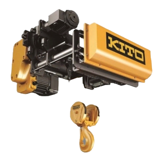
RY Series Wire Rope Hoist (2.8t to 5t)
Disassembly and Reassembly Manual
Safety precaution
This Disassembly and Reassembly Manual includes contents to prevent injury to any person performing
Disassembly and reassembly, users, and other persons and damage to property, and to disassemble/
reassemble the Wire rope hoist safely and correctly.Before performing disassembly/reassembly, be sure to
read and follow this manual as well as the RY series Wire Rope Hoist Owner's Manual (separate document)
since its contents are also important for Disassembly/reassembly.Disassembly/reassembly of the Wire rope
hoist are required operations for regular inspection and repair.Carry out disassembly/reassembly properly in
accordance with these manuals.
Persons performing disassembly/reassembly
Disassembly/reassembly shall be performed by a competent person (a person duly authorized by the company as having expertise on the structure
and device of the Wire rope hoist) or consult KITO.
Low Headroom Type: RYL
AS-RYLZZZ-MGE-01
Advertisement
Table of Contents

Subscribe to Our Youtube Channel
Related Manuals for KITO RY Series


Summary of Contents for KITO RY Series
- Page 1 Wire rope hoist safely and correctly.Before performing disassembly/reassembly, be sure to read and follow this manual as well as the RY series Wire Rope Hoist Owner's Manual (separate document) since its contents are also important for Disassembly/reassembly.Disassembly/reassembly of the Wire rope hoist are required operations for regular inspection and repair.Carry out disassembly/reassembly properly in...
-
Page 2: Safety Precautions
Safety Precautions Improper use of the hoist may cause serious accidents resulting in death or severe injury such as drop of lifted load. Read this Disassembly and Reassembly Manual carefully before installation, operation and maintenance. Use the product after understanding the product knowledge, safety information and precautions.This Disassembly and Reassembly Manual classifies the safety information and precautions into three categories of“DANGER”,“WARNING”, and “CAUTION”. - Page 3 Disassembly/reassembly by anyone other than competent persons may result in death or sever injury. Prohibited • Do not use unauthorized parts for RY Series Wire Rope Hoist. Even if the part is an authorized part, it may not be used for a different model.
- Page 4 • When reassembling, replace the following parts with new ones. • Gear grease (Type and required amount of grease vary depending on the specification and main body size. Refer to the separated "RY Series Wire Rope Hoist Owner's Manual". Mandatory •...
-
Page 5: Table Of Contents
Table of Contents Safety Precautions .................2 Table of Contents ................5 Disassembly and assembly tool ...........6 Major parts in common ..............7 Name of parts..................8 Disassembly procedure ..............9 1. Wire rope ..................9 2. Hook block ..................13 3. Anchorage ..................16 4. Idle sheave .................18 5. -
Page 6: Disassembly And Assembly Tool
Disassembly and assembly tool For disassembly and reassembly, prepare the following tools. Tool/jig name Application Icon Wrench 7 mm/8 mm/13 mm/16 mm/18 mm/ Bolts and nuts 19 mm/22 mm/24 mm/30 mm Hexagon wrench Socket bolts 3mm/5mm/6mm/8mm/10mm/14mm Snap ring pliers S Snap rings (shaft) Snap ring pliers R Snap rings (hole) -
Page 7: Major Parts In Common
Major parts in common The table below indicates the major parts in common when the destination and power source are the same. Rated load 2.8 t/3 t/3.2 t Rail width (mm) 125-175 176-350 351-500 Difference 10.2 10.2 10.2 Lifting range (m) Frame A, B, C, and D Length Suspension shaft... -
Page 8: Name Of Parts
Name of parts Upper lower Rope guide Limit switch Rope drum Guide roller Direct limit switch (Option) Gear box Idle sheave Motor (for lifting) Wire rope Anchorage Hook latch Hook Frame D Frame B Frame A Frame C Wheel Motor (for traversing) Control box Suspension shaft... -
Page 9: Disassembly Procedure
Disassembly procedure DANGER • Do not disassemble the rope hoist while it is being suspended. Doing so may result in death or severe injury due to a falling part. Place it on the floor and perform maintenance on the workbench. Prohibited The overall disassembly procedure is shown below. - Page 10 If it is difficult to tap the tip of the cotter, put a slotted screw driver on the cotter as shown in the figure and tap the driver with a hammer. Socket (6) Remove the Wire Rope from the socket. Wire Rope (7) Pull out slowly the Wire Rope from the Hook Sheave of Wire Rope...
- Page 11 There are two types of Rope Guides with different shapes of connecting parts as shown below. Understand the structures of the Rope Guides first and perform the procedures for each type to remove or attach parts. Shim Guide C Guide B Guide C Guide B Guide A...
- Page 12 12-2. Loosen the socket bolt connecting Guide A to Socket Bolt Guide C, and remove Guide A from the Rope Guide A Support Shaft Drum at a position where Guide A has no interference with the Support Shaft. 12-3. As shown in the figure on the right, rotate Guide A and Guide C along the Rope Drum with Guide A removed from the Rope Drum.
-
Page 13: Hook Block
Hook block ■ Removing the hook block (1) Pull out the spring pin fixing the hook nut and hook. Pin punch Hook nut Spring pin (2) Remove the hook nut fixing the hook. Hook nut Hook (3) Remove the thrust bearing from the hook. Hook Thrust bearing... - Page 14 (4) Remove the hook from the trunnion hole. Trunnion hole Hook (5) Remove the hex nuts and spring lock washers fixing the sheave covers A and B. 24mm Spring lock washer (6) Remove the sheave cover A. Hex nut Sheave cover A (7) Remove the snap ring fixing the sheave subassembly.
- Page 15 (9) Remove the sheave cover B from the trunnion. Trunnion Sheave cover B (10) Pull out the spring pin from the L bracket. Spring pin L bracket (11) Remove the parts on the opposite side in the same way. Follow the steps from (5) to (10).
-
Page 16: Anchorage
Anchorage ■ Removing the anchorage (1) Remove the socket bolts and spring lock washers (two Shaft locations for each) of the key plate fixing the shaft of the anchorage, and remove the key plate. [5mm] Spring lock washer Anchorage Key plate Socket bolt (2) Pull out the shaft of the anchorage from the hole of the beam A, and remove the anchorage. - Page 17 ■ Disassembling the anchorage (1) Remove the snap ring fixing the anchorage shaft. Anchorage shaft Anchorage hanger (2) Pull out the anchorage shaft from the anchorage Socket hanger and socket. Snap ring (3) Remove the hex nuts (two locations), and remove the wire clip at the rope end.
-
Page 18: Idle Sheave
Idle sheave ■ Removing the idle sheave (1) Remove the socket bolts (two locations) of the key plate fixing the sheave support, and remove the key plate. Sheave support [5mm] Key plate Socket bolt Spring lock washer (2) While supporting the idle sheave by hand to prevent Sheave support it from dropping, pull out the sheave support from the hole of the beam B and frame C, and remove the idle... -
Page 19: Lifting Motor
Lifting motor ■ Removing the lifting motor harness (terminal box side) ● For 200V-03S, 03H, 05S, 400V-03S, 03H, 05S, and 05H Lifting motor harness (1) Cut the cable band fixing the lifting motor harness to the joint plate. Cable band Joint plate (2) Remove the round head screws and spring lock washers (four locations for each) fixing the terminal... - Page 20 (4) Cut the cable band fixing the insulation cap, and re- move the insulation caps (three locations). Cable band When removing plastic insulation caps, refer to the procedure • Insulation cap below. How to remove a) While pushing here, b) remove the cap downwards. After removal (5) Remove the round head screw, spring lock washer, and hex nut each connecting the lead wires (red,...
- Page 21 (6) a) Remove the cap of the cable gland. b) Pull out the lifting motor harness. c) Return the cap of the cable gland to the main body of the cable gland. ① ② Lifting motor harness ③ Cable gland main body ●...
- Page 22 (3) Cut the cable bands (three locations) fixing the insu- lation caps (three locations). Cable band Insulation cap (4) Remove the round head screw, spring lock washer, and hex nut for connecting the motor wire to the lift- ing motor harness. Black [7mm/8mm] White...
- Page 23 ■ Removing the lifting motor (1) Suspend the lifting motor with a fiber sling, etc., remove the socket bolts (four locations) fixing the lifting motor, and remove the lifting motor from the gear box. [14mm] Lifting motor Socket bolt Gear box Lead wire When removing the lifting motor, make sure not to let •...
- Page 24 (2) Remove the socket bolts and toothed lock washers (four locations for each) fixing the fan cover, and remove the fan cover. Socket bolt [6mm] Toothed lock washer Fan cover Snap ring (3) Remove the snap ring and fan washer for installing the fan, and remove the fan.
- Page 25 (5) Remove the socket bolts and spring lock washers (four locations for each) of the motor cover. Socket bolt [10mm] Spring lock washer Motor brake Motor cover Stator (6) Insert the flathead screwdriver into a gap of the matching surfaces of the motor cover (two diagonal locations).
- Page 26 ■ Disassembling the motor brake (1) Use the flathead screwdriver to return the nut washer Flathead screwdriver claw to be flat, and rotate the adjusting nut to remove. Nut washer Adjusting nut Motor cover (2) Remove the nut washer and spacer, and remove the Motor shaft motor cover from the motor shaft.
- Page 27 (4) Tighten the pull rotor and rotor with the vise, and remove the pull rotor holder. Vise Pull rotor 2 pieces Pull rotor holder Rotor Put in two pull rotor holders. • Pull rotor holder Pull rotor (5) Remove the vise, and remove the pull rotor and pull rotor spring.
-
Page 28: Rope Drum
Rope drum ■ Removing the LS harness (1) Remove the socket bolts, spring lock washers, and Drum cover large plain washers (eight locations for each) install- ing the drum cover. [3mm] Socket bolt Spring lock washer Large plain washer (2) Cut all the cable bands fixing the LS harness to the Support shaft support shaft and mount base. - Page 29 (4) Loosen the round head screw fixing the lead wire of Round head screw Round head screw the limit switch, and remove the lead wire from the limit switch. Lead wire Hex nut When removing the lead wire of the Lower limit switch, •...
- Page 30 (2) Remove the socket bolts and hex nuts fixing the con- Washer Socket bolt Hex nut nection pins B (two locations) of the back frame side, Spring lock washer and remove the washers and spring lock washers. Washer [10mm] [19mm] Back frame Connection pin B (3) Remove the snap rings outside of the connection...
- Page 31 (5) Remove the rope drum unit from the frame A and frame C. Frame A Frame C Rope drum unit ■ Disassembling the rope drum (1) Place the rope drum unit with the back frame side Back frame facing up. (2) Remove the socket bolts, spring lock washers, and plain Back frame washers (three locations for each) of the back frame.
- Page 32 (4) Loosen the hex nuts (two locations) of the limit switch bolt (hereinafter referred to as LS bolt) on the back Hex nut frame side. [18mm] LS bolt (5) While hammering at the back side of the back frame Back frame with the plastic hammer, remove the back frame.
- Page 33 (8) Wind the fiber sling around the rope drum. While lifting the rope drum with a crane gradually, pull it out straight. Rope drum Gear shaft ■ Disassembling the gear box Gear case (1) Place the gear box on the sleeper with the gear case side facing up.
- Page 34 (4) Remove the packing, and remove the set pins (two Set pin locations). Packing Set pin (5) Remove the lubricating oil (grease) in the body. Remove it using the spatula and the like. • Lubricating oil (6) Remove the bearing at the tip of the gear 2 sub- Bearing for gear 2 subassembly Bearing for pinion assembly, and remove the bearing at the tip of the...
- Page 35 (8) Remove the gear 2 subassembly Gear 2 subassembly (9) Remove the gear shaft subassembly Gear shaft subassembly (10) Remove the bearing for gear 4 subassembly Bearing for gear 4 subas- sembly (11) Use the screwdrivers (-) and the like to re- move the oil seal for gear shaft.
- Page 36 (13) a) Remove the socket bolts (three locations) for installing the bearing holder. Socket bolt b) Remove the bearing holder. Bearing holder c) Remove the pinion subassembly. d) Use the screwdriver (-) and the like Pinion subassembly to remove the oil seal for pinion. [5mm] Oil seal for pinion...
-
Page 37: Direct Limit Switch
Direct limit switch ■ Removing the direct limit switch (1) Remove the hex nut fixing the fixing bracket of the Suspension direct limit switch, and remove the direct limit switch shaft from the suspension shaft. [16mm] Fixing bracket Hex nut ■... - Page 38 (5) Remove the hex low nut from the lever shaft, and pull out the lever shaft from the sensor bracket and lever Hex low nut Lever shaft bracket. [16mm] Lever subassembly [8mm] (Sensor bracket) (6) Loosen the hex nut B, pull out the fixing bolt, and remove the sensor bracket and switch plate.
- Page 39 (3) Loosen the screw fixing the DLS harness, and re- move the DLS harness. loosen loosen (4) Pull out the DLS harness from the wiring cover, and return the wiring cover to the limit switch. DLS harness Wiring cover (5) Cut the cable band bundling the DLS harness and 2 LS harnesses on the control box side, and pull out Suspension shaft the DLS harness from the suspension shaft.
-
Page 40: Control Box
Control box ■ Removing the control box unit Counter weight (1) Install the eye type bolt M12 to the screw holes (two Eye type Bolt locations) of the counter weight on both sides. (Ring internal diameter 30 mm) (2) Pass the chain sling through the eye type bolts (two locations). - Page 41 (4) Remove the socket bolts (two locations for each) of the key plates (two locations), and remove the key Counter weight plates from the counter weight. [5mm] Socket bolt Key plate (5) While pulling out the lifting motor harness from the Control box unit suspension shaft, remove the control box unit.
- Page 42 ■ Disassembling the control box Positions of the harness and the like are shown below. Lifting motor harness Traversing resistor Traversing motor harness Power supply Distortion OLL Inverter Inverter Option for traversing Movement signal harness for lifting DLS harness Resistor harness LS harness (ULS) LS harness (LLS) Push button...
- Page 43 (2) Cut the cable band fixing the resistor harness to the mount base. Cable band Resistor harness Mount base (3) Remove the round head screw, spring lock washer, and hex nut each connecting the lifting resistor to the resistor harness, and remove the resistor harness and lead wire.
- Page 44 ■ Removing the internal wiring and electrical components Cover ● Removing the lifting inverter (1) Remove the cover of the lifting inverter Round head screw (2) Cut the cable band bundling the harness (lead wire) as necessary. (3) Pull out the harness (H1 and H2) from the lifting inverter.
- Page 45 (2) Remove the internal cover of the traversing inverter. Internal cover (3) Remove the cover stay of the traversing inverter. Cover stay (4) Cut the cable band bundling the harness (lead wire) as necessary. (5) Pull out the harness (H1 and H3) from the traversing inverter.
- Page 46 ● Removing the traversing resistor (1) Pull out the harness from the traversing resistor. The traversing resistor is not installed on products • where the first two serial number digits are 18 or higher. Refer to the wiring diagram in the separated "RY •...
-
Page 47: Traversing Motor
Traversing motor ■ Removing the traversing motor harness (terminal box side) (1) Cut the cable band fixing the traversing motor har- ness to the adjusting bolt. Cable band Adjusting bolt Traversing motor harness (2) Remove the round head screws and spring lock Round head screw washers (four locations for each), and remove the Spring lock washer... - Page 48 (4) Remove the round head screws and spring lock washers (three locations for each) fixing the cable packing and cable holder. Make sure not to let the lead wire get caught and remove the traversing motor harness from the terminal box. Packing Traversing motor harness Cable holder...
- Page 49 ■ Disassembling the traversing motor ● Disassembling the brake Round head screw (1) Remove the 4 round head screws and 4 spring lock Spring lock washer Terminal cover washers, and remove the terminal cover and terminal cover packing. Terminal cover packing (2) Remove the lead wires (two locations) inserted into the rectifier.
- Page 50 (5) Remove the socket bolts (four locations). [5mm] Socket bolt Socket bolt (6) Apply the flat screwdriver (-) to the insertion positions (two Electromagnetic brake assembly locations). Hammer it gently with the plastic hammer, and re- Screwdriver (-) insertion position move the electromagnetic brake assembly.
- Page 51 (9) Remove the armature and brake disk fitted into the brake bracket. Armature Brake disk (10) Remove the snap ring at the end of the motor shaft. Snap ring Motor shaft (11) Apply the screwdriver (-) to the insertion position. Screwdriver (-) insertion position Hammer the screwdriver gently with the plastic ham- mer, and remove the brake bracket.
- Page 52 ● Removing the stator and rotor Stator (1) Remove the socket bolts (four locations), and remove the stator. [5mm] Socket bolt (2) Hold the rotor. While hammering the gear case B gently with the plastic hammer, remove the rotor. Rotor Gear case B Hammer gently with the plastic hammer at the position indicated with arrows.
- Page 53 ● Disassembling the gear box Socket bolt (1) Remove the socket bolts and spring lock washers Spring lock washer (four locations for each) fixing the gear case B, and remove the gear case B and packing. [5mm] Gear case B Packing Gear case A (2) Remove the snap ring of the pinion.
- Page 54 (5) Remove the snap ring fixing the bearing, and remove the bearing. Snap ring Bearing...
-
Page 55: Trolley Frame
Trolley frame ■ Removing the frame A/B/C/D (1) Place the frame A /B and frame C/D on the sleep- er with the beam installation side facing up as shown in the figure. Sleeper (2) Remove the reamer bolts (two locations for each: four locations in total) of the frame A and frame C. - Page 56 Since the components are different, there are two methods for mounting the frames to the suspension shaft: type A and type B.Follow the disassembly procedure for your type. Type A Socket bolt Frame B (5) Loosen the hex nut fixed to the bush of the frame A Hex nut or frame B (one location for each), and remove the Frame A...
- Page 57 (9) Remove the hex nuts (three locations) outside of the frame A, and pull out the frame A from the adjusting bolt. Frame A Adjusting bolt [30mm] Hex nut Frame A Adjusting bolt (10) Remove the hex nut and spring lock washer outside Frame B of the frame B, and pull out the frame B from the Hex nut...
- Page 58 Since the components are different, there are two methods for mounting the frames to the suspension shaft: type A and type B.Follow the disassembly procedure for your type. Type A Socket bolt (11) Loosen the hex nut fixed to the bush of the frame C Hex nut or D (one location for each), and remove the socket Frame D...
- Page 59 (15) Remove the hex nut and spring lock washer outside of the frame D, and pull out the adjusting bolt from Hex nutSpring the frame D. lock washer [30mm] Frame D Adjusting bolt Frame D Adjusting bolt (16) Remove the remaining hex nuts from each of the adjusting bolts (two locations for each).
- Page 60 ■ Disassembling the frame A ● Removing the rubber buffer/guide roller (1) Remove the socket bolts A (two locations), and re- Frame A move the rubber buffer from the frame A. Rubber Buffer Socket bolt B [10mm] Socket bolt A (2) Remove the socket bolts B (two locations) fixing the guide roller, and remove the guide roller from the Spring lock washer...
- Page 61 ● Removing the wheel A (1) Remove the socket bolts, spring lock washers, and Socket bolt plain washers (four locations for each) fixing the Spring lock washer wheel cover A, and remove the wheel cover A. Plain washer Frame A [5mm] Wheel cover A (2) Remove the snap ring fixing the wheel A, and remove...
- Page 62 ■ Disassembling the frame B ● Removing the rubber buffer/guide roller (1) Remove the socket bolts A (two locations) fixing the rubber buffer, and remove the buffer from the frame B. Frame B Buffer Socket bolt B [10mm] Socket bolt A (2) Remove the socket bolts B and spring lock washers Spring lock washer (two locations for each) fixing the guide roller, and...
- Page 63 ● Removing the wheel A Wheel cover B (1) Remove the socket bolts, spring lock washers, and plain washers (four locations for each) fixing the wheel cover B, and remove the wheel cover B. [5mm] Socket bolt Spring lock washer Large plain washer (2) Remove the snap ring fixing the wheel A subassem- bly, and remove the wheel A subassembly from the...
- Page 64 ■ Disassembling the frame C ● Removing the buffer/guide roller Rubber buffer (1) Remove the socket bolts A (two locations) fixing the buffer, and remove the buffer from the frame C. Socket bolt B Socket bolt A [10mm] Spring lock washer (2) Remove the socket bolts B and spring lock washers (two locations for each) fixing the guide roller, and remove the guide roller from the frame C.
- Page 65 ■ Disassembling the frame D ● Removing the rubber buffer/guide roller (1) Remove the socket bolts A (two locations) fixing the Rubber buffer rubber buffer, and remove the buffer from the frame D. [10mm] Socket bolt A (2) Remove the socket bolt B and spring lock washer (two Guide roller locations for each) fixing the guide roller, and remove Spring lock washer...
-
Page 66: Reassembly Procedures
Reassembly Procedures Trolley frame ■ Assembling Frame A (1) Insert a bearing for idle gear into Frame A. Be careful not to scratch the bearing. • Scocket bolt (2) <For 4.8t and 5t hoists> Secure the bearing with a snap ring. Spring lock washer <For 2.8t, 3t, and 3.2t hoists>... - Page 67 (5) Install a snap ring to the axle. Axle Snap ring The snap ring must not be protruding. • (6) Apply lubricant to the teeth of both the idle gear and Wheel A subassembly. Wheel A sub assembly Lubricant: EPNOC AP (N) No. 2 •...
- Page 68 (8) Using a plastic hammer, secure a collar, a bearing, and then a guide roller to the guide roller shaft. Plastic hammer Guide roller shaft Collar Bearing Guide roller shaft Guide roller (9) Fix a rubber buffer to the buffer bracket by using a hex nut and a spring lock washer.
- Page 69 ■ Assembling Frame B (1) Insert a bearing for idle gear into Frame B. Be careful not to scratch the bearing. • Socket bolt Spring lock washer Large plain washer (2) <For 4.8t and 5t hoists> Fix the bearing with a snap ring. <For 2.8t, 3t, and 3.2t hoists>...
- Page 70 (5) Install a snap ring to the axle. Axle Snap ring (6) Apply lubricant to the teeth of both the idle gear and the Wheel A subassembly. Lubricant: EPNOC AP (N) No. 2 • Wheel A subassembly The lubricant must be applied to the entire •...
- Page 71 (9) Fix a rubber buffer to the buffer bracket by using a hex nut and a spring lock washer. Hex nut [13mm] Rubber buffer M8 torque setting: 18 N・m Buffer bracket (10) Install the guide roller to Frame B by using two socket bolts and two spring lock washers.
- Page 72 ■ Assembling Frame C (1) Insert the Wheel B subassembly into the axle. Wheel B subassembly Axle Snap ring (2) Install a snap ring to the axle into which the Wheel B subassembly has been inserted. (3) Using a plastic hammer, secure a collar, a bearing, and then a guide roller to the guide roller shaft.
- Page 73 (5) Install the guide roller to Frame C by using two Socket Bolt As and two spring lock washers. [5mm] Buffer bracket Torque M6 torque setting: 8 N・m Socket bolt length • 2.8 t/3 t/3.2 t: 30 mm Socket bolt A 4.8 t/5 t: 35 mm Guide roller (6) Fix the buffer bracket to Frame C by using two Socket...
- Page 74 ■ Assembling Frame D (1) Insert the Wheel B subassembly into the axle. Wheel B subassembly Axle (2) Install a snap ring to the axle. Snap ring (3) Using a plastic hammer, secure a collar, a bearing, and then a guide roller to the guide roller shaft.
- Page 75 (5) Install the guide roller to Frame D by using two Socket Bolt As and two spring lock washers. [5mm] Buffer bracket Torque Socket bolt B M6 torque setting: 8 N・m Socket bolt A Socket bolt length • 2.8 t/3 t/3.2 t: 30 mm 4.8 t/5 t: 35 mm Spring lock washer (6) Install the buffer bracket to Frame D by using two Socket...
- Page 76 ■ Assembling all frames Frame D (1) Pass one suspension shaft through Frame A and Frame B and another suspension shaft through Frame Frame C C and Frame D, and then place them on sleepers as shown in the figure to the right. Frame B Frame A Suspension shaft...
- Page 77 (6) Pass the adjusting bolt through Frame B, and then install a spring lock washer and a hex nut onto the adjusting bolt. Hex nut Spring lock washer Hold the nut with its tapered end facing away from • Adjusting bolt the adjusting bolt when you thread the nut onto the adjusting bolt.
- Page 78 Since the components are different, there are two methods for mounting the frames to the suspension shaft: type A and type B.Follow the disassembly procedure for your type. Type A Bush (9) Screw in and tighten a socket bolt (with a hex nut) against the bush adjoining Frame B to lock the suspen- sion shaft in place.
- Page 79 (11) Pass the adjusting bolt through Frame D, and then thread a spring lock washer and a hex nut onto the ad- justing bolt. Hex nut Hold the nut with its tapered end facing away from the • Spring lock washer adjusting bolt when you install the nut onto the adjust- ing bolt.
- Page 80 Since the components are different, there are two methods for mounting the frames to the suspension shaft: type A and type B.Follow the disassembly procedure for your type. Type A (14) Screw in and tighten a socket bolt (with a hex nut) onto Bush the bush adjoining Frame D to fix the suspension shaft in place.
- Page 81 (16) Join Frame B with Frame D by loosely fastening Beam Beam A Frame D A to them by using four reamer bolts, four spring lock washers, four hex nuts, four spring lock washers, and Reamer bolt four plain washers. Spring lock washer Frame B Hex nut...
- Page 82 (20) Screw in and loosely tighten a socket bolt (with a hex nut) against the bush adjoining Frame A. (Similarly, remember to only loosely tighten the hex nut.) Fully tighten the socket bolt and the hex nut only after • lifting the main unit and adjusting the distance be- Hex nut tween frames.
-
Page 83: Traversing Motor
Traversing Motor Gear Case A (1) Insert two bearings into Gear Case A, and then fix them in place with a snap ring. Snap ring Bearing (2) Hold a round bar against a pinion, and then with a plas- Pinion tic hammer, lightly tap on the round bar to insert the pin- ion. - Page 84 (5) Apply lubricant to Gear Case A and Gear 2. Gear 2 Gear Case A Lubricant: EPNOC AP (N) No. 2 • (For details about the amount of lubricant to be used, Lubricant see the owners' manual.) (6) With a plastic hammer, drive two pins into the gear case. Pins (7) Install a packing, making sure that the pins are aligned with the holes on the packing.
- Page 85 (9) With a plastic hammer, lightly tap on a rotor to drive it into Gear Case B. Rotor Lightly tap on the rotor with a plastic hammer. Gear Case B (10) Fix a stator to Gear Case B by using four socket bolts. Stator [5mm] Torque...
- Page 86 (12) Install a brake bracket, making sure that the spring pin Align this hole with the spring pin. is aligned with the hole on the brake bracket. With a plastic hammer, lightly tap on the brake bracket to • make it engage with the stator. Spring pin Snap ring (13) Install a snap ring to the motor shaft.
- Page 87 Brake spring the opening on the spring holder, screw in an adjusting bolt. [10mm] [28mm] For details about how to adjust the brake, see the "Owners' Spring holder • Manual for KITO Rope Hoist RY Model (10 t)". Adjusting bolt...
- Page 88 (20) After tightening the adjusting bolt to the designated torque, screw in a lock nut to prevent the adjusting bolt from becoming loose. [28mm] Lock nut (21) Lay the lead wire routed to the terminal box as shown in the figure to the right. Where each end of the lead wire should be con- nected to ■...
- Page 89 ■ Installing the traversing motor harness (1) Remove the three round head screws and three spring lock washers fixing the cable holder in place. Packing Cable holder Spring lock washer Round head screw (2) Wrap black plastic tape around the traversing motor harness about four times, and then pass the traversing motor harness through the cable holder and the packing.
- Page 90 (4) Secure the ground wire (green/yellow) from the travers- ing motor harness to the inside of the terminal box by using a screw. Connect the remaining three lead wires (red, white, and black wires) to Terminal 1, Rectifier, and Terminal 3, re- spectively.
-
Page 91: Control Box
Control Box (1) Lay the ground wire over the internal plate and route it to the control box. The traversing resistor is not installed on products Hex nut • where the first two serial number digits are 18 or higher. Internal plate [13mm] [6mm]... - Page 92 (7) Connect each harness to an inverter or a terminal. For details, see the wiring diagram provided in the • "Owners' Manual for KITO Rope Hoist RY Model (2.8 - 5 t)". (8) Tie harnesses together with a cable band.
- Page 93 (9) Install a cover stay to the traversing inverter. Cover stay (10) Install an internal cover to the traversing inverter. Internal cover (11) Install covers to the lifting inverter and the traversing inverter. Round head screw Cover Traversing motor Lifting inverter Cover Round head screw (12) Let a small loop at the end of two fall-prevention wires...
- Page 94 ■ Installing lifting resistors (1) Fix the lifting resistors to the counter weight by using two Socket bolts Spring lock washers socket bolts and two spring lock washers. [5mm] Torque M8 torque setting: 16 N・m 03S: One lifting resistor • 03H/05S/05H: Two lifting resistors •...
- Page 95 (4) Fix the resister harness to the mount base by Cable band using a cable band. Resister harness Mount base (5) Remove the four socket bolts and four spring lock wash- ers, and then insatll the resistor cover to the counter weight.
- Page 96 (2) Secure the ground wire to the internal plate by using a hex nut. [13mm] Hex nut Internal plate Ground wire (3) Close the lid on the control box by using eight machine Machine screw with screws with spring washers. spring washer ■...
- Page 97 ■ Installing the control box unit (1) While inserting the lifting motor harness into the suspen- sion shaft, install the control box unit to both the suspen- Lifting motor harness sion shaft and the adjusting bolt. Control box unit Suspension shaft Adjusting bolt (2) Install two key plates to the counter weight by using two socket bolts each.
-
Page 98: Direct Limit Switch
Direct Limit Switch ■ Installing the DLS harness Suspension shaft (1) Pass a DLS harness through the suspension shaft locat- ed on the right of the control box, and pull it out from the rope-drum side. Note that the DLS harness must come out from the correct side. - Page 99 (4) Attach the wiring cover to the direct limit switch. Wiring cover (5) Wrap a spiral tube around 100 mm of the DLS harness, Spiral tube and fix the DLS harness to the adjusting bolt with a ca- ble band. Cable band Adjusting bolt (6) With a cable band, tie the inserted DLS harness and the...
- Page 100 (2) Engage the lever bracket with the sensor bracket. Sensor bracket Lever bracket (3) Insert the lever shaft halfway in. Lever shaft (4) Install a hex low nut onto the lever shaft and tighten it. Hex low nut [16mm] Lever shaft Hole on the lever bracket (5) As shown in the figure to the right, insert the claws of the Hole on the sensor bracket...
- Page 101 (6) Holding down the spring, pass the lever shaft through the spring and through the sensor bracket and the lever Lever shaft Spring subassembly. Lever subassembly (sensor bracket) Lever shaft (7) Insert a split pin into the hole on the tip of the lever shaft. Split pin Sensor bracket Lever bracket...
- Page 102 (10) By using two hex nuts and two spring lock washers, fix the direct limit switch to the fixing bracket, with the suspension shaft placed between them. Mount the direct limit switch to the suspension shaft located between Spring lock Frame C and Frame D.
-
Page 103: Rope Drum Unit
Rope Drum Unit ■ Assembling the gear box (1) Place the body on the sleepers, with the surface on which to install the lifting motor facing up. Body Sleeper Sleeper (2) Apply lubricant (grease) to the lip and outer circumfer- ence of the oil seal for pinion. - Page 104 (6) Turn the body upside down and place it on the sleepers. Sleeper (7) Apply lubricant (grease) to the lip and outer circumference of the oil seal for gear shaft. Oil seal: AE2085A0 • Lubricant (grease): EPNOC AP (N) No. 2 •...
- Page 105 (11) Apply lubricant (grease) to the outer surface of the Bearing for bearing for gear 2 subassembly, and then install the the gear 2 subassembly bearing into the body. Lubricant (grease): EPNOC AP (N) No. 2 • Bearing for gear 4 (12) Apply lubricant (grease) to the outer surface of the bear- subassembly ing for gear 4 subassembly, and insert it into the body,...
- Page 106 (15) Install two set pins, cover them with a packing, and posi- Set pin tion the body such that it is aligned with the outer circum- ference of the gear case. Packing Set pin (16) Install the gear case to the body, making sure Socket bolt that the set pins on the body is aligned with the holes on the gear case.
- Page 107 (19) Attach a cable gland to the side of the gear box. * For the 200V-05H speed model, the terminal cover • is box-shaped, in which case a blind-type cable gland must be installed at the usual position. Cable gland Cable gland (blind type) 200V-05H ■...
- Page 108 (4) Install three support shafts to the body. [24mm] Support shaft Torque M16 torque setting: 120 N・m Body The locations to which to attach the support shafts Install the support shafts to the correct locations, as • shown in the figure to the right. (5) Install an LS bolt to the gear box and fix it in place with a hex nut.
- Page 109 (7) Screw in three socket bolts to lock the back frame to the Back frame support shafts. Socket bolt [10mm] Spring lock washer Torque Plain washer M12 torque setting: 69 N・m Back frame (8) Tighten the two hex nuts on the LS bolt against the back frame.
- Page 110 (2) Put fiber slings around the two support shafts located on the upper section of the rope drum unit, and lift the rope drum unit while keeping it level. (3) Adjust the height of the rope drum unit so that the con- necting hole on the rope drum unit is aligned with the one on the trolley frame unit.
- Page 111 (7) Install a snap ring to each of the two Connection Pin As. Connection Pin A Snap ring (8) Apply connection washers to both ends of Connection Connection Pin B Hex nut Pin Bs, and then by using socket bolts, hex nuts, and spring lock washers, lock Connection Pin Bs in place.
- Page 112 ■ Installing the LS harnesses Suspension shaft (1) Insert LS harnesses into the suspension shaft located on the right of the control box, and pull it out from the opposite side. Note that the LS harnesses must come out from the correct side. DLS harness LS harnesses The DLS harness must come...
- Page 113 (5) Attach the wiring covers to the limit switches. Fix them in place after confirming that the openings on these covers, from which the upper-limit-side and low- er-limit-side LS harnesses come out, are facing each other. Openings from which LS harnesses come out There are two types of Lifting limit switch: type A and type B.
- Page 114 Australia Type B setting position For details on how to adjust the stop position, refer to “RY Series Wire Rope Hoist Owner's Manual”. (7) As shown in the figure to the right, lay the LS harnesses Secured to the support shaft...
-
Page 115: Lifting Motor
Lifting Motor ■ Assembling a lifting motor (1) Fit a pull rotor spring and a pull rotor into the rotor as- Pull rotor spring sembly. Indentation Be careful not to insert the pull rotor upside down. • The side with the indentations must be facing out- ward. - Page 116 (4) Put four Pull Rotor Spring Ms on top of one another, positioning each as shown in the figure to the right. Positioning of each Pull Rotor Spring M Motor shaft (5) Install Spacer M and the motor cover to the motor shaft, and then install a spacer and a nut washer, in that order.
- Page 117 (8) Fix the motor brake and the stator in place by using four socket bolts and four spring lock washers. Socket bolt Spring lock washer [10mm] Stator Torque Motor cover M12 torque setting: 60 N・m Motor brake (9) Install a key to the motor shaft and install an O-ring. O-ring Motor shaft (10) Install a fan to the motor shaft, making sure that...
- Page 118 ■ Installing the lifting motor (1) Install set pins to the surface of the gear box where the Set pins lifting motor is to be installed, by lightly tapping on them with a plastic hammer. Packing (2) Install a packing to the gear box, making sure that the pins on the gear box are aligned with the holes on the packing.
- Page 119 (4) Fix the lifting motor to the gear box by using four socket bolts. Lifting motor Socket bolts [14mm] Torque M12 torque setting: 120 N・m Gear box ■ Installing the lifting motor harness ● (200 V-03S, 03H, 05S, 400 V-03S, 03H, 05S, 05H) (1) Remove the cap from the cable gland, and pass the lifting motor harness through the removed cap and then the cable gland.
- Page 120 (2) Secure the ground wire (green/yellow), which is one of the four lead wires of the lifting motor harness, to the inside of the terminal box with a screw. Connect the remaining three lead wires (red, white, and black) with the lead wires (with tubes Black White that have U, V, and W markings on them) extending from the...
- Page 121 (5) Place the connected lead wires inside the terminal box, and fix the terminal packing and terminal cover to the terminal box by using four round head screws and four spring lock washers. Terminal box Terminal packing Terminal cover Torque M5 torque setting: 2.5 N・m Spring lock washer Round head screw...
- Page 122 (3) Secure the ground wire (green/yellow), which is one of the four Ground wire lead wires of the lifting motor harness, to the inside of the ter- minal box with a screw. Connect the remaining three lead wires (red, white, and black) with the lead wires (with tubes that have U, V, and W markings on them) extending from the lifting motor in combinations of red-U, white-V, and black-W, by using round head screws, spring lock washers, and hex nuts.
- Page 123 (6) Place the connected lead wires inside both the terminal box and the terminal cover, and install the terminal cover and the terminal packing to the terminal box with four round head screws and four spring lock washers. Terminal box Terminal packing Terminal cover If, after installation, it turns out that the length of the exposed...
-
Page 124: Idle Sheave
Idle Sheave ■ Assembling the idle sheave (1) Slide a spacer, a sheave hanger, and then a sheave onto the idle sheave shaft. Idle sheave shaft Sheave hanger Spacer Spacer Key plate (2) Align a key plate to the groove on the idle shave shaft, and then fix it in place by using two socket bolts and two Spring lock spring lock washers. -
Page 125: Anchorage
Anchorage ■ Assembling the anchorage (1) Draw a wire rope through a sheave hanger. Pay attention to the position of the sheave hanger (remember to draw a wire rope through the side that has no R attached to it). (2) Insert a cotter. (3) Draw a wire rope through a gap between the cotter and the sheave hanger. - Page 126 (6) Install a snap ring to the anchorage shaft. Snap ring Anchorage shaft ■ Installing the anchorage (1) Install the shaft of the anchorage to Beam Subassembly Beam Subassembly A A and the anchorage subassembly. Shaft Anchorage subassembly (2) Align a key plate to the groove on the shaft of the anchorage, and then fix it in place by using two socket Shaft bolts and two spring lock washers.
-
Page 127: Hook Block
Hook Block ■ Assembling the hook block (1) Press the spring pin into the L-bracket. Spring pin L-bracket (2) Fit Sheave Cover B onto the trunnion. Trunnion Sheave Cover B (3) Slide the sheave onto the trunnion shaft. Sheave Trunnion shaft (4) Fix the sheave in place with a snap ring. - Page 128 (5) Fix Sheave Cover A and Sheave Cover B in place by using a hex nut and a spring lock washer. Spring lock washer [24mm] Hex nut Torque M16 torque setting: 153 N・m Sheave Cover B Sheave Cover A (6) Install all the parts on the opposite side as well by fol- lowing the same procedure.
- Page 129 (9) Screw in the hook nut onto the head of the hook. Hook nut Confirm that the hook turns. • Before installing the hook nut, apply lubricant to • the thrust bearing. Lubricant: EPNOC-AP(N)-2 Hook (10) Align the hole on the hook nut with the hole on the hook, and insert a spring pin into the hole.
-
Page 130: Wire Rope
Wire rope ■Installing Wire Rope WARNING Convex part • Wind the Wire Rope following the wire rope groove on the Rope Drum. Winding the Wire Rope over the convex part of the wire rope groove (refer to the figure on the right) will not only impair the proper functionality and performance of the Wire Rope Hoist, but Mandatory could also cause the Wire Rope Hoist to malfunction, resulting in a serious accident. - Page 131 (5) After fixing the Wire Rope, rotate the Rope Drum slowly, and place the Wire Rope in the Rope Drum’s groove from the groove’s start point. When doing so, lightly pull on the Wire Rope while rotating the Rope Drum in the lifting direction to prevent the Wire Rope from floating as you place the Wire Rope in the groove of the Rope Drum.
- Page 132 7-4. As shown in the figure on the right, rotate Guide A and Guide C along the Rope Drum using the Guide Roller as a guide. Rope Drum Guide Roller (8) Move Guide A toward the Reduction Gear side until CAUTION: For the Type B Rope Guide, put the Shim in the part its Guide Roller lies on the Wire Rope on the Rope connecting Guide A to Guide C.
- Page 133 (11) Paying attention to a passing position, pass the Wire Rope through the Idle Sheave. (12) Pass the Wire Rope through the other Hook Sheave of the Hook Block. (13) Pass the Wire Rope through the socket. Be careful about the position. (Pass the Wire Rope from the side not having an arc shape [R-shape].) (14) Insert the cotter.
- Page 134 (18) Firmly fix the tip of the fixed end shaft with the snap ring. Snap ring (19) In order to securely attach the cotter to the socket after installing the Hoist on the rail, lift the Hook Block from the floor. Then, raise the block by approx.
- Page 136 URL. http://www.kito.com...
Need help?
Do you have a question about the RY Series and is the answer not in the manual?
Questions and answers