KITO ER2 Series Disassembly And Reassembly Manual
Electric chain hoist
Hide thumbs
Also See for ER2 Series:
- Owner's manual (164 pages) ,
- Owner's manual supplement (14 pages) ,
- Operation manuals (9 pages)
Table of Contents
Advertisement
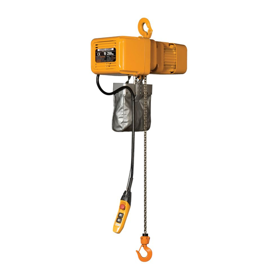
ER2 Series Electric Chain Hoist (125kg to 5t)
Disassembly and Reassembly Manual
Safety precaution
This Disassembly and Reassembly Manual includes contents to prevent injury to any person performing
disassembly and reassembly, users, and other persons and damage to property, and to disassemble/
reassemble the electric chain hoist safely and correctly.
Before performing disassembly/reassembly, be sure to read and follow this manual as well as the ER2
Series Electric Chain Hoist Owner's Manual (separate document) since its contents are also important for
disassembly/reassembly.
Disassembly/reassembly of the electric chain hoist are required operations for regular inspection and repair.
Carry out disassembly/reassembly properly in accordance with these manuals.
Persons performing disassembly/reassembly
Disassembly/reassembly shall be performed by a competent person (a person duly authorized by the company as having expertise on the structure
and device of the electric chain hoist) or consult KITO.
AS-ER2ZZZ-MGE-00
1
Advertisement
Table of Contents

Related Manuals for KITO ER2 Series


Summary of Contents for KITO ER2 Series
- Page 1 Carry out disassembly/reassembly properly in accordance with these manuals. Persons performing disassembly/reassembly Disassembly/reassembly shall be performed by a competent person (a person duly authorized by the company as having expertise on the structure and device of the electric chain hoist) or consult KITO.
-
Page 2: Safety Precaution
Disassembly/reassembly by anyone other than competent persons may result in death or sever injury. Prohibited • Do not use unauthorized parts for KITO Electric Chain Hoist. Even if the part is an authorized part, it may not be used for a different model. - Page 3 Before disassembly and reassembly Danger • Only competent persons with expertise and experience must disassemble/reassemble the electric chain hoist. Alternately, contact the nearest distributor or KITO. Disassembling/reassembling improperly causes death or severe injury. Mandatory • Perform disassembly and reassembly in correct procedures as described in the manual.
-
Page 4: Table Of Contents
Table of Contents Safety precaution ..................2 Table of Contents ..................4 Disassembly and assembly tool ..............5 Name of parts ..................6 Disassembly procedure ................8 1 Removing the outer circumference parts ........8 2 Removing the controller cover .............9 3 Removing the top hook ..............14 4 Disassembling the gear parts .............15 5 Disassembling the load chain circumference ......18 6 Disassembling the motor and electromagnetic brake ....19... -
Page 5: Disassembly And Assembly Tool
Disassembly and assembly tools For disassembly and reassembly, prepare the following tools. Tool name Application Icon Wrench Bolts and nuts 10mm / 13mm / 17mm / 19mm Hexagon wrench Socket bolts 4mm / 5mm / 6mm / 8mm / 10mm Snap ring pliers S (Large) (Small) Snap rings (shaft) Snap ring pliers R... -
Page 6: Name Of Parts
Name of parts Controller cover The structure and names of parts in the controller cover are shown on the next page for each model. Top hook Packing G Shaft clip Gear case Oil seal Friction clutch Load gear Load sheave Body Plate A Top pin... - Page 7 Single speed type / Dual speed pole change type Plate Controller cover Limit switch Packing C Dual speed inverter type (Basic main body B/C type) Plate Inverter Controller cover Braking resistor Limit switch Resistor cover Interface board Packing C Name plate ...
-
Page 8: Disassembly Procedure
Disassembly procedure Danger • Do not disassemble the electric chain hoist while it is being suspended. Failure to follow this instruction may result in death or severe injury due to dropped parts. Be sure to place the electric chain hoist on a floor and perform the disassembly on the workbench. Prohibited The overall disassembly procedure is shown below. -
Page 9: Removing The Controller Cover
(3) When disassembling the gear part, remove Oil plug B (for oilhole) the oil plug (for waste oil hole) and plug Body packing from the bottom of the gear case, and then remove gear oil. Check stain and viscosity of the removed oil. •... - Page 10 Disassembly procedure (continued) (4) Remove the limit switch as required. Remove 4 lead wires (connectors) of the limit switch first. • Loosen the 3 socket bolts to remove the limit switch • (replace the O ring attached to the shaft with a new part upon reassembly).
- Page 11 (2) Remove the connector and ground line connected to the controller cover. Braking resistor To remove the ground line, loosen the pan-head machine • lead wire screw of the plate side. Ground line Pan-head machine screw Controller cover (3) Remove the socket bolt (gear case side) Controller cover securing the cover belt, and remove the controller cover from the gear case.
- Page 12 Disassembly procedure (continued) (5) Remove the limit switch as required. Remove the connector of the limit switch first. • Remove it carefully by holding the connector of the limit • switch side. Loosen the 3 socket bolts to remove the limit switch •...
- Page 13 (3) Remove the socket bolt (gear case side) Controller cover securing the cover belt, and remove the controller cover from the gear case. The controller cover can be removed with the cover belt • attached. Socket bolt (gear case side) Cover belt Ground line (4) Remove the lead wire and connector...
-
Page 14: Removing The Top Hook
Disassembly procedure (continued) Removing the top hook Remove the top hook first to make it easier to disassemble other parts. Removing the top hook (Basic main bodies B, C, D, and E) Shaft clip Top hook or (1) Loosen the socket bolt to remove the Plate Presser Suspender part... -
Page 15: Disassembling The Gear Parts
Disassembling the gear parts (1) Remove the friction plug from the gear case Friction plug as required. Slot for removal For the friction clutch with mechanical brake ("friction • clutch with mechanical brake" hereafter) specification, this operation is not required. (2) Loosen the 4 socket bolts (5 for F type). - Page 16 Disassembly procedure (continued) Danger • Do not disassemble the friction clutch or friction clutch with mechanical brake. Failure to follow this instruction may result in death or severe injury due to a falling load. Prohibited Double reduction The gear configuration as shown to the right is the double •...
- Page 17 Triple reduction The gear configuration with Gear B built in as shown • Gear B to the right is the triple reduction specification. Perform disassembly in the following steps. (4) Remove Gear B from the bearing of the Friction clutch with Release mechanical brake gear plate.
-
Page 18: Disassembling The Load Chain Circumference
Disassembly procedure (continued) Disassembling the load chain circumference (1) Remove the stopper and cushion rubber from the load chain (no load side). Cushion rubber For the double chain type, also remove the stopper of the • load side. Socket bolt Stopper (2) Remove the load chain from the body to the load side. -
Page 19: Disassembling The Motor And Electromagnetic Brake
Disassembling the motor and electromagnetic brake (1) Loosen the 4 socket bolts, and remove the Socket bolt fan cover. Fan cover (2) Remove the snap ring. Snap ring (3) Insert the "pawl" part of the puller to the Puller outer circumference bottom of the fan to remove the fan. - Page 20 Disassembly procedure (continued) (5) Remove the brake cover. If it is difficult to remove, hammer it gently with a plastic • hammer to remove. Be careful not to hammer it too much to cause • deformation. (6) Remove the brake wiring. Hold the male and female bullet terminals to remove it.
- Page 21 (9) Remove the V ring, snap ring, Packing B, and hub. Be careful not to scratch the motor junction face. • Some models don't have the snap ring (for hub bottom). • Remove the hub using a puller. • V ring Spline hub is also available.
-
Page 22: Disassembling The Body Part
Disassembly procedure (continued) (10) Remove the 4 socket bolts. Hammer the Loosen socket stator gently with a plastic hammer to bolts (x4). remove it from the body. Turn it over so that the stator is facing down and the body •... - Page 23 (2) Place the body sideways. Hammer the pinion gently to remove the bearing holder (including the pinion). Pinion (Integrated with the bearing and bearing holder) (3) Hammer the load sheave gently as shown in the figure to remove it. Hold the load sheave with hands to prevent it from falling. •...
-
Page 24: Reassembly Procedure
Reassembly procedure Danger • Do not perform reassembly using parts exceeding application limits. • For parts to be replaced with new parts upon reassembly, refer to page 3. • Tighten the bolts and nuts securely with the specified torques. Mandatory •... - Page 25 (3) Install the oil seal with machine oil applied to the load sheave securely. Install it fully so that the flat part faces the direction as • shown in the figure. Bearing After installation, apply additional oil on the lip •...
- Page 26 Reassembly procedure (continued) (7) Insert the pinion (with the bearing) to the bearing holder. If it is difficult to insert the pinion, hammer it gently with a • Pinion plastic hammer. Bearing Bearing holder (8) Insert the bearing bearer (integrated with Torque Socket the pinion) to the body.
-
Page 27: Assembling The Motor And Electromagnetic Brake
Assembling the motor and electromagnetic brake (1) Press-fit the bearings at 2 locations on the motor shaft. Snap ring Bearing (For hub (2) Install a Snap ring between the key groove (For rotor) driving) and Bearing. Install it so that the key slot and snap ring opening are in •... - Page 28 Reassembly procedure (continued) (6) Install the hub to the motor shaft. Hub installation cross-sectional view If it is difficult to insert, hammer it gently with a plastic • Snap ring Motor Snap Motor hammer. shaft ring shaft Press down until the slot to which a snap ring is mounted •...
- Page 29 Brake (8) Install the electromagnetic brake with the Tighten with Torque (Disassembly (three) bolts 3 socket bolts. is prohibited.) Check the orientation of the electromagnetic brake. • Refer to the position data recorded upon disassembly. Electromagnetic brake gap Check that the lead wire is not too long or too short for •...
- Page 30 Reassembly procedure (continued) (11) Install the fan. If the fit is hard and it is difficult to install, set a proper jig • and hammer it gently with a plastic hammer. Be careful not to hammer the motor shaft or fan directly. •...
-
Page 31: Connecting The Motor And Body
Connecting the motor and body (1) Install the 2 set pins and Packing M to the motor. Pass through the wiring hole of the body. Body Pass the (2) Mount the body on the motor. lead wire. Chain Guide A Mount it so that the Chain Guide A side of the body is in •... -
Page 32: Installing The Load Chain
Reassembly procedure (continued) Installing the load chain Rotate with hand. (1) Install the load chain so that the welded part Load side No load side comes outside of the load sheave. (insert from the Insert it to the main body from the horizontal link (or •... - Page 33 (3) Re-check the orientation of the load chain, and check for any twist. (4) Install the stopper and cushion rubber or chain spring to the 3rd link from the end of the no load side load chain as they were No load side chain before disassembly.
-
Page 34: Assembling The Gear Parts
Reassembly procedure (continued) Assembling the gear parts Double reduction Mechanical brake specification (option) Pawl shaft • Pawl spring (1) Insert the pawl spring and pawl to the pawl (Replace it with shaft, and lock them with a snap ring. a new part if worn.) Check the orientation so that the pawl is in engagement •... - Page 35 Danger • Do not adjust the friction clutch or friction clutch with mechanical brake. Failure to follow this instruction may result in death or severe injury. Prohibited Triple reduction (1) Insert the load gear to the load sheave, and Fig. A Orientation of the load gear Friction clutch with lock it with a new snap ring.
- Page 36 Reassembly procedure (continued) (3) Press-fit the bearing for the pinion to the Bearing gear case using a proper jig. Oil seal Cross-sectional shape Bearing (triple reduction (4) Install the oil seal to the gear case using a specification proper jig. only) (5) Install the friction plug by hammering it with a plastic hammer.
-
Page 37: Installing The Top Hook
Installing the top hook Assembling the top hook (Basic main bodies B, C, D, and E) Top hook or Shaft clip (1) Install the top hook by inserting the 2 top Suspender pins. Top pin (2) Install Plate A (for Top pin) with Socket bolt (1 piece) and Shaft clip on the opposite Plate A side. - Page 38 Reassembly procedure (continued) Double chain When the reassembly of the top hook of Basic main body E/F is complete, install the load chain. (1) Insert Load chain from the load side of Chain Guide A through Limiting plate, Chain spring, Bottom hook, and Chain spring in that order.
-
Page 39: Assembling The Controller Cover
Assembling the controller cover J Single speed type Caution • Be careful so that your finger won't get caught by the panel plate. Mandatory (1) Fix the plate securely with the 3 setscrews. Draw out from Align the elongate hole of the plate to the fulcrum pin head the notch of •... - Page 40 Reassembly procedure (continued) (4) Install the cover belt to the gear case. Socket bolt Plain washer (gear case side) Pass the cover belt through Controller Cover Packing C. • Tighten the socket bolt while holding the controller cover Controller • Cover Packing C with hands.
- Page 41 Holder C (upper side) Holder C (lower side) (10) Install the chain bucket to the main body. For information on how to install various types of buckets, refer to ER2 Series Electric Chain Hoist Owner's Manual (separate • document). (To be continued)
- Page 42 Reassembly procedure (continued) J Dual speed inverter type (Basic main body B/C type) Caution • Be careful so that your finger won't get caught by the panel plate. Mandatory (1) Fix the plate securely with the 3 setscrews. Draw out from the notch of the plate.
- Page 43 (4) Install the cover belt to the gear case. Socket bolt Torque (gear case side) Pass the cover belt through Controller Cover Packing C. • Controller cover Tighten the socket bolt while holding the controller cover Spring lock • packing C washer with hands.
- Page 44 Reassembly procedure (continued) J Dual speed inverter type (Basic main body D/E/F type) Caution • Be careful so that your finger won't get caught by the panel plate. Mandatory (1) Fix the plate securely with the 3 setscrews Remove the lead wire and the inverter with the 2 pan-head in advance.
- Page 45 (4) Install the cover belt to the gear case. Socket bolt Torque (gear case side) Pass the cover belt through Controller Cover Packing C. • Spring lock Tighten the socket bolt while holding the controller cover • Controller cover washer with hands.
-
Page 46: Installing The Bottom Hook (If Removed From The Chain)
Reassembly procedure (continued) Installing the bottom hook (if removed from the chain) Caution • Check the load side of the load chain to install the bottom hook. Mandatory 2t or more Installing single type Bottom hook For 2t or more, pass the limiting plate and chain spring •... - Page 47 Installing double type Bottom hook Idle sheave Fix with a double spanner (1) Apply grease to Thrust bearing. Grease Bottom shaft assembly (2) Face the smaller internal diameter of Thrust bearing to the A side (upper side) of Thrust Stopper to incorporate it into Hook.
-
Page 48: Oil Filling
(3) Place a new packing on the oil plug B (for oilhole) and tighten it. Use Kito genuine gear oil. (Refer to the oil quantity on the next page.) * The friction clutch with mechanical brake specification has a sticker that indicates “With mechanical brake"... -
Page 49: Operation Check, Etc
If any part is left, perform disassembly and reassembly again for correct assembly. • (2) Perform daily inspection. For details, refer to "Daily inspection" in ER2 Series Electric Chain Hoist Owner's Manual (separate document). • (3) After checking that no error occurs with no load, perform an operation test with a rated load. - Page 50 Memo...
- Page 51 Memo...
- Page 52 URL. http://www.kito.com...
Need help?
Do you have a question about the ER2 Series and is the answer not in the manual?
Questions and answers