Advertisement
Quick Links
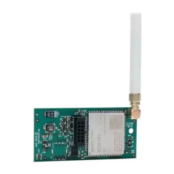
263LTE-FN CELLULAR
COMMUNICATOR
Installation Guide
Figure 1: 263LTE-FN
DESCRIPTION
The 263LTE-FN Cellular
Communicator provides
a fully-supervised alarm
communication path over a
reserved AT&T network. The
module installs on the panel
inside the enclosure and is
powered by the panel so no
additional enclosure, power
supply, or battery back-up is
needed.
The 263LTE-FN is
FirstNet Ready™.
Compatibility
•
XR150/XR550 Series
panels with Version 202 or
higher
•
XT30/XT50 Series Panels
with Version 202 or higher
What is Included
•
263LTE-FN Cellular
Communicator
•
383 antenna
•
PCB standoff
•
Hardware pack
1
INSTALL THE 263LTE-FN
Caution: Touch grounded metal to discharge
static before handling the panel.
XT30/XT50 Series Panels
1.
Open the panel enclosure, set the reset
jumper, and remove power from the panel.
2. Insert the included standoff into the
panel standoff hole.
3. Align the 263LTE-FN SMA antenna connector
with the antenna hole in the top of the panel
enclosure, place one washer around the
connector, and secure it on the 12-pin cell
module connector. See Figure 2.
Note: For XT50 panels, install the included
washers between the antenna and the panel.
4. Align the 263LTE-FN standoff hole with the
standoff already placed in the panel and
snap it into place.
Standoff and
Standoff Hole SMA Connector
Figure 2: 263LTE-FN on an XT30/XT50 Panel
XR150/XR550 Series Panels
1.
Open the panel enclosure, set the reset
jumper, and remove power from the panel.
2. Insert the included standoff into the
XR150/XR550 Series panel standoff hole.
3. Secure the 263LTE-FN on the 12-pin cell
module connector. See Figure 3.
4. Align the 263LTE-FN standoff hole with the
standoff already placed in the panel and
snap it into place.
Back of the
263LTE-FN
Figure 3: 263LTE-FN on an XR150/XR550 Panel
Back of the
263LTE-FN
Washer (XT50 only)
Standoff and
Standoff Hole
1
2
3
4
Advertisement

Related Manuals for DMP Electronics 263LTE-FN


Summary of Contents for DMP Electronics 263LTE-FN
- Page 1 12-pin cell module connector. See Figure 2. Note: For XT50 panels, install the included washers between the antenna and the panel. 4. Align the 263LTE-FN standoff hole with the DESCRIPTION standoff already placed in the panel and snap it into place.
- Page 2 1. If installing an XT50, place the second washer around the 263LTE-FN SMA connector and connect it to the included antenna at the hole in the top of the panel. 2. Connect the 263LTE-FN SMA connector to the included antenna at the hole in the top of the panel. See Figure 4.
- Page 3 The panel provides a diagnostic function to test the communication integrity and cellular signal strength of the 263LTE-FN to the nearest tower for the cellular carrier. To use the diagnostic function, reset the panel, enter 2313 (DIAG), and press CMD.
- Page 4 établies par le Code de sécurité 6 de Santé Canada. Le système doit être installé à une distance minimale de 7.87 pouces (20 cm) séparant l’antenne d’une personne présente en conformité avec les limites permises d’exposition du grand public. 263LTE-FN CELLULAR Underwriters Laboratory (UL) Listed • ANSI/UL 294 Access Control System Units COMMUNICATOR •...
Need help?
Do you have a question about the 263LTE-FN and is the answer not in the manual?
Questions and answers