Table of Contents
Advertisement
Quick Links
Inside US: +1 (877) 432-9908
Outside US: +1 (717) 767-6511
www.redlion.net
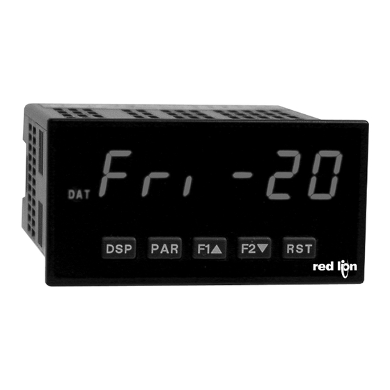
MODEL PAX ‐ 1/8 DIN PRESET TIMER (PAXTM) & REAL‐TIME CLOCK (PAXCK)
U L
C
US LISTED
PROC. CONT. EQ.
E179259
GENERAL DESCRIPTION
The PAXTM (PAX
®
Timer) and PAXCK (PAX
features and performance capabilities to suit a wide range of industrial
applications. Both can function as an Elapsed Timer or Preset Timer,
while the PAXCK also offers Real-Time Clock with Date capability. The
option cards allow the opportunity to configure the meter for the present
application, while providing easy upgrades for future needs.
Both units can function as an Elapsed Time Indicator. By using two
separate signal inputs and 23 selectable timer ranges, the meters can be
programmed to meet most any timing application. By adding a setpoint
option card, they can easily become a dual or quad output preset timer.
The PAXCK can also operate as a Real-Time Clock (RTC), with the
Real-Time Clock Card already installed. The meter is capable of
displaying time in 12 or 24-hour time formats. The 12-hour format can be
displayed in hours and minutes, with or without an AM/PM indication or in
hours, minutes, and seconds. The 24-hour format can be displayed in
hours and minutes or in hours, minutes, and seconds. The PAXCK is also
capable of a calendar display in which the day, month and/or year can be
displayed. The meter will recognize leap years, and can automatically
adjust for Daylight Savings Time. The Real-Time Clock has the ability to
externally synchronize with other PAXCK meters to provide a uniform
display network throughout the plant.
If the application calls for both a Preset Timer and a Real-Time Clock at
the same time, the PAXCK can handle this requirement as well. The
meter provides up to four different displays, accessed via front panel push
buttons or external inputs. The displays are Timer (TMR), which displays
the current timer value; Count (CNT), which displays the current cycle
counter value; Date (DAT), which displays the current programmed date;
and Real-Time Clock, which displays the current time. A battery-backed
Real-Time Clock card is provided with the PAXCK. This card, which
includes a lithium coin-cell battery, will maintain the time and date when
main power is removed.
The meters accept inputs from a variety of sources including switch
contacts and outputs from CMOS or TTL circuits. The input can be
configured to trigger on the edge or level of the incoming pulse. Internal
jumpers are available to allow the selection for sinking inputs (active low)
or sourcing inputs (active high).
The front panel keys and three user inputs are programmable to
perform various meter functions. One of the functions includes
exchanging parameter lists, allowing for two separate listings of setpoint
DIMENSIONS In inches (mm)
TMR
CNT
DAT
SP1
SP2
SP3
PAR
F1
F2
DSP
3.80
(96.5)
®
Clock/Timer) offer many
1.95
(49.5)
SP4
RST
.10
(2.5)
•
6-DIGIT 0.56" RED SUNLIGHT READABLE DISPLAY
4 SEPARATE DISPLAYS (TIMER, COUNTER, REAL-TIME CLOCK,
•
AND DATE)
•
CYCLE COUNTING CAPABILITY
PROGRAMMABLE FUNCTION KEYS/USER INPUTS
•
•
FOUR SETPOINT ALARM OUTPUTS (W/OPTION CARD)
COMMUNICATION AND BUS CAPABILITIES (W/OPTION CARD)
•
•
BUS CAPABILITIES: DEVICENET, MODBUS AND PROFIBUS-DP
CRIMSON
®
PROGRAMMING SOFTWARE
•
•
NEMA 4X/IP65 SEALED FRONT BEZEL
values, timer start/stop values, counter start/stop values and RTC daily on
and off values.
Optional digital output cards provide the meter with up to four setpoint
outputs. The cards are available as dual relay, quad relay, quad sinking
transistor, quad sourcing transistor/SSR drive, or dual triac/dual SSR
drive outputs. The setpoint alarms can be configured to suit a variety of
control and alarm requirements.
Communication and Bus Capabilities are also available as option
cards. These include RS232, RS485, Modbus, DeviceNet, and Profibus-
DP. Readout values and setpoint alarm values can be controlled through
the bus. Additionally, the meters have a feature that allows a remote
computer to directly control the outputs of the meter. With an RS232 or
RS485 card installed, it is possible to configure the meter using a
Windows
®
based program. The configuration data can be saved to a file
for later recall.
Once the meters have been initially configured, the parameter list may
be locked out from further modification entirely, or the setpoint, timer start/
stop values, counter start/stop values, RTC time SET, and Display
Intensity can be made accessible. This lockout is possible through a
security code or user input.
The meters have been specifically designed for harsh industrial
environments. With a NEMA 4X/IP65 sealed bezel and extensive testing
to meet CE requirements, the meter provides a tough yet reliable
application solution.
SAFETY SUMMARY
All safety related regulations, local codes and instructions that appear
in this literature or on equipment must be observed to ensure personal
safety and to prevent damage to either the instrument or equipment
connected to it. If equipment is used in a manner not specified by the
manufacturer, the protection provided by the equipment may be impaired.
Do not use this unit to directly command motors, valves, or other
actuators not equipped with safeguards. To do so can be potentially
harmful to persons or equipment in the event of a fault to the unit.
CAUTION: Risk Of Danger.
Read complete instructions prior to
installation and operation of the unit.
Note: Recommended minimum clearance (behind the panel) for mounting clip installation is
2.1" (53.4) H x 5.0" (127) W.
1.75
(44.5)
4.10
(104.1)
-1-
Bulletin No. PAXCK-J
Drawing No. LP0524
Released 2018-05-15
CAUTION: Risk of electric shock.
12
16
20
13
17
21
14
18
22
1.75
15
19
23
24
(44.5)
25
1
2
3
4
5
6
7
8
9
10
11
3.60 (91.4)
Advertisement
Table of Contents

Related Manuals for red lion PAXTM


Summary of Contents for red lion PAXTM
- Page 1 PROC. CONT. EQ. E179259 values, timer start/stop values, counter start/stop values and RTC daily on GENERAL DESCRIPTION and off values. The PAXTM (PAX ® Timer) and PAXCK (PAX ® Clock/Timer) offer many Optional digital output cards provide the meter with up to four setpoint features and performance capabilities to suit a wide range of industrial outputs.
-
Page 2: Table Of Contents
Bulletin No. PAXCK-J Released 2018-05-15 Drawing No. LP0524 TABLE OF CONTENTS Ordering Information ..............2 4.0 Wiring the Meter ..............7 Using This Manual..............3 5.0 Reviewing the Front Buttons and Display......9 Crimson Programming Software ..........3 6.0 Programming the Meter ............ 10 General Meter Specifications ........... -
Page 3: Using This Manual
Released 2018-05-15 Bulletin No. PAXCK-J Drawing No. LP0524 USING THIS MANUAL This manual contains installation and programming instructions for the available through Crimson. The programming section of the manual will PAX and all applicable option cards. To make installing the option card serve to provide expanded explanations some... -
Page 4: General Meter Specifications
Bulletin No. PAXCK-J Released 2018-05-15 Drawing No. LP0524 GENERAL METER SPECIFICATIONS 1. DISPLAY: 6 digit, 0.56" (14.2 mm) red sunlight readable or standard 11.USER INPUTS: Three programmable user inputs green LED Logic inputs configurable as Current Sinking (active low) or Current 2. -
Page 5: Option Cards
Bulletin No. PAXCK-J Released 2018-05-15 Drawing No. LP0524 OPTION CARDS WARNING: Disconnect all power to the unit before REAL-TIME CLOCK CARD: PAXRTC00 installing option cards. Time Accuracy: ± 5 secs./Month (1 min./year) with end-user calibration Battery: Lithium 2025 coin cell Battery Life Expectancy: 10 yrs. -
Page 6: Installing The Meter
Released 2018-05-15 Bulletin No. PAXCK-J Drawing No. LP0524 1.0 INSTALLING THE METER While holding the unit in place, push the panel latch over the rear of Installation the unit so that the tabs of the panel latch engage in the slots on the case. The PAX meets NEMA 4X/IP65 requirements when properly installed. -
Page 7: Installing Option Cards
Visit RLC’s web site at http://www.redlion.net/emi for more information and heaters, etc. The cables should be run through metal conduit that on EMI guidelines, Safety and CE issues as they relate to Red Lion is properly grounded. This is especially useful in applications where... - Page 8 Released 2018-05-15 Bulletin No. PAXCK-J Drawing No. LP0524 4.1 POWER WIRING AC Power DC Power AC AC Terminal 1: VAC Terminal 1: +VDC Terminal 2: VAC Terminal 2: -VDC 4.2 TIMER SIGNAL WIRING Before connecting signal wires, the Timer Input logic jumper must be verified for proper position. Two Wire Proximity, Current Source Current Sinking Output Current Sourcing Output...
-
Page 9: Reviewing The Front Buttons And Display
Bulletin No. PAXCK-J Released 2018-05-15 Drawing No. LP0524 4.4 SETPOINT (ALARMS) WIRING See appropriate option card bulletin for details. 4.5 SERIAL COMMUNICATION WIRING 4.6 REAL‐TIME CLOCK WIRING (PAXCK) Time synchronization between multiple PAXCK meters can be accomplished through a hardware interface on the Real-Time Clock SYNC option card. -
Page 10: Programming The Meter
Released 2018-05-15 Bulletin No. PAXCK-J Drawing No. LP0524 6.0 PROGRAMMING THE METER OVERVIEW DISPLAY MODE PROGRAMMING MENU User Input/ Display/ Predefined* Function Program Cycle Timer Setpoint* Serial* Real-Time* Factory Operating Lock-out Count (Alarm) Communication Clock (RTC) Service Timer Input Parameters Parameters Parameters Modes Parameters Parameters... - Page 11 Bulletin No. PAXCK-J Released 2018-05-15 Drawing No. LP0524 6.1 MODULE 1 ‐ TIMER INPUT PARAMETERS PARAMETER MENU 1-INP rANgE INP OP FILtEr t dir t Strt t StOP FLASH InP-UP t P-UP Flash Timer Timer Timer Input Timer Input Timing Timer Start Timer Stop Timer Input Timer Reset Range Operation...
- Page 12 Released 2018-05-15 Bulletin No. PAXCK-J Drawing No. LP0524 FLASH TIMER ANNUNCIATOR TIMER RESET AT POWER‐UP This parameter allows the Timer annunciator (TMR) to flash when the The Timer can be programmed to Reset at each meter power-up. Timer is running or stopped/inhibited.
- Page 13 Bulletin No. PAXCK-J Released 2018-05-15 Drawing No. LP0524 DISPLAY HOLD DISPLAY SELECT (Level Active) (Level Active) When active (maintained action), meter continuously scrolls through all displays that are not “locked-out” in the Display mode. (See Module 3 for ...
- Page 14 Released 2018-05-15 Bulletin No. PAXCK-J Drawing No. LP0524 CHANGE DISPLAY INTENSITY LEVEL OUTPUT SET (Level Active) When activated (momentary action), the display intensity changes to When activated (maintained action), the meter continually activates the the next intensity level (of 4).
- Page 15 Released 2018-05-15 Bulletin No. PAXCK-J Drawing No. LP0524 6.3 MODULE 3 ‐ DISPLAY ASSIGNMENT AND PROGRAM LOCK‐OUT PARAMETERS ( PARAMETER MENU PAXCK PAXCK ONLY ONLY RTC Date Timer Cycle Counter Setpoint ** Setpoint ** Setpoint ** RTC Time Display Display Display Off Value Time-out Display On Value Lock-out Access Lock-out Lock-out...
- Page 16 Released 2018-05-15 Bulletin No. PAXCK-J Drawing No. LP0524 6.4 MODULE 4 ‐ CYCLE COUNTER PARAMETERS ( PARAMETER MENU 4-CNt C Src C dir C Strt C StOP C P-UP Cycle Counter Cycle Counter Cycle Counter Cycle Counter Cycle Counter Count Source Count Direction Start Value Stop Value Reset at Power-up...
- Page 17 Bulletin No. PAXCK-J Released 2018-05-15 Drawing No. LP0524 should be entered directly in Module 5 after selecting the operating mode. parameters for Setpoint 1 ( ) in Module 6 are automatically Only the value parameters which apply to the selected mode are configured to implement the selected operating mode.
- Page 18 This section of the bulletin replaces the bulletin shipped with the Dual and when activated and “on” when deactivated. Quad Setpoint option cards. Discard the separate bulletin when using Setpoint option cards with the PAXCK and PAXTM. SETPOINT ON SETPOINT SELECT ...
- Page 19 Bulletin No. PAXCK-J Released 2018-05-15 Drawing No. LP0524 the Setpoint is assigned ( ). When assigned to the Timer or Cycle PAXCK: DAILY OFF OCCURENCE Counter, the value is entered in the same format as the assigned display. When assigned to the Real-Time Clock Date Display ( ), the date ...
- Page 20 4.5 Serial Communication Wiring. time clock master. See Serial Real-time Clock Master Adressing. This section of the PAXTM/CK bulletin replaces the bulletin shipped with the RS232 and RS485 serial communications option cards. Discard the ABBREVIATED PRINTING...
- Page 21 Bulletin No. PAXCK-J Released 2018-05-15 Drawing No. LP0524 PRINT OPTIONS DISPLAY PARAMETER FACTORY MNEMONIC Timer Cycle Counter RTC Date * This parameter selects the meter values transmitted in response to a ...
- Page 22 Example: SP1 assigned to RTC. RTC format = 12:00 P. 3. Address = 0, Reset Timer value SP1 printout = 12:00 P. String: RA* Note: When communicating with a Red Lion Controls HMI unit, set Transmitting Data To the Meter Numeric data sent to the meter must be limited to Transmit Details in programming module 7 (serial) to .
- Page 23 Bulletin No. PAXCK-J Released 2018-05-15 Drawing No. LP0524 COMMAND RESPONSE TIME SERIAL TIMING The meter can only receive data or transmit data at any one time (half- PROCESS TIME (t COMMAND COMMENT duplex operation). During RS232 transmissions, the meter ignores Reset 2-50 msec. commands while transmitting data, but instead uses RXD as a busy Write 100-200 msec.
- Page 24 Released 2018-05-15 Bulletin No. PAXCK-J Drawing No. LP0524 6.8 MODULE 8 ‐ REAL‐TIME CLOCK PARAMETERS ( ) ‐ PAXCK PARAMETER MENU 8-rtC SEt-t SEt-d dSP-t dSP-d Ch-dSt SYNC Set Time Date Display Set Date Set Day Time Display Auto Change Meter Type Calibrate for Clock Format Format for Daylight Real-Time Savings Time...
-
Page 25: Factory Service Operations (9-Fcs)
Bulletin No. PAXCK-J Released 2018-05-15 Drawing No. LP0524 CALIBRATE REAL‐TIME CLOCK IF RTC CLOCK GAINED TIME: IF RTC CLOCK LOST TIME: USE VALUE FROM THIS TABLE USE VALUE FROM THIS TABLE SECONDS GAINED ENTER THIS SECONDS LOST ENTER THIS IN 30 DAYS OFFSET VALUE IN 30 DAYS OFFSET VALUE ... -
Page 26: Troubleshooting
ERROR CODE ( Shaded areas are model dependent. If for any reason you have trouble operating, connecting, or simply have questions concerning your new unit, contact Red Lion’s technical support. Email: support@redlion.net Website: www.redlion.net Inside US: +1 (877) 432-9908 Outside US: +1 (717) 767-6511 PAXCK Application... -
Page 27: Parameter Value Chart
Bulletin No. PAXCK-J Released 2018-05-15 Drawing No. LP0524 PARAMETER VALUE CHART Programmer ________________ Date ________ PAXCK Clock Timer Meter# _____________ Security Code __________ Display and Program Lock-out Parameters Timer Input Parameters FACTORY FACTORY DISPLAY PARAMETER USER SETTING DISPLAY PARAMETER USER SETTING SETTING SETTING... - Page 28 Released 2018-05-15 Bulletin No. PAXCK-J Drawing No. LP0524 Setpoint (Alarm) Parameters FACTORY FACTORY FACTORY FACTORY DISPLAY PARAMETER USER SETTING USER SETTING USER SETTING USER SETTING SETTING SETTING SETTING SETTING SETPOINT ASSIGNMENT SETPOINT ACTION OUTPUT LOGIC SETPOINT ON (A) SETPOINT ON (B)* SETPOINT ON VALUE (A) SETPOINT ON VALUE (B)* SETPOINT OFF (A)
-
Page 29: Programming Quick Overview
Bulletin No. PAXCK-J Released 2018-05-15 Drawing No. LP0524 PAXTM/PAXCK PROGRAMMING QUICK OVERVIEW -29-... - Page 30 Released 2018-05-15 Bulletin No. PAXCK-J Drawing No. LP0524 This page intentionally left blank -30-...
- Page 31 Released 2018-05-15 Bulletin No. PAXCK-J Drawing No. LP0524 This page intentionally left blank -31-...
- Page 32 Drawing No. LP0524 LIMITED WARRANTY (a) Red Lion Controls Inc., (the “Company”) warrants that all Products shall be free from defects in material and workmanship under normal use for the period of time provided in “Statement of Warranty Periods” (available at www.redlion.net) current at the time of shipment of the Products (the “Warranty Period”).
Need help?
Do you have a question about the PAXTM and is the answer not in the manual?
Questions and answers