Table of Contents
Advertisement
Quick Links
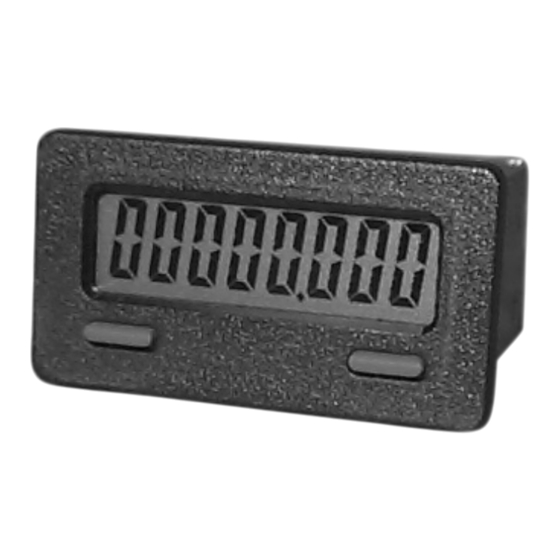
MODEL CUB7 – MINIATURE ELECTRONIC 8 DIGIT COUNTER or TIMER
U L
C
US LISTED
R
3RSD
PROCESS CONTROL EQUIPMENT
DESCRIPTION
The CUB7 series is an 8-digit lithium battery powered miniature counter or
timer with large 0.35" (8.9 mm) high digits. It has an LCD read-out available in
Positive Imagine Reflective, Negative Image Transmissive with yellow/green or
red backlighting. The backlight versions require an external 6-26 VDC power
supply. The CUB7 series is housed in a lightweight, high impact plastic case
with a clear viewing window. The sealed front panel with silicon rubber keypad
meets NEMA 4X/IP65 specification for wash-down and/or dusty environments,
when properly installed with supplied panel gasket and mounting clip.
Both counter and timer CUB7 models are available with a low voltage input
(28 VDC max) or an isolated high voltage input (50-250 VDC/VAC). The low
voltage input has DIP switch selections for SINKING or SOURCING along
with a HIGH/LOW FREQUENCY selection (low frequency for contact inputs).
Both units have front panel keypads that can be used to reset the display. The
keypad can be enabled/disabled via a single DIP switch. The standard unit uses
22 gauge wires for external connections, an optional plug-in terminal block is
available.
SAFETY SUMMARY
All safety related regulations, local codes and instructions that appear in the
literature or on equipment must be observed to ensure personal safety and to
prevent damage to either the instrument or equipment connected to it. If
equipment is used in a manner not specified by the manufacturer, the protection
provided by the equipment may be impaired.
CAUTION: Risk of Danger.
Read complete instructions prior to
installation and operation of the unit.
DIMENSIONS In inches (mm)
1.10
(27.9)
2.00 (50.8)
l 0.35" (8.9 mm) HIGH LCD DIGITS, REFLECTIVE OR TRANSMISSIVE
WITH YELLOW/GREEN OR RED BACKLIGHTING (6-26 VDC power
supply required for version with LED backlighting)
l INTERNAL LITHIUM BATTERY PROVIDES UP TO 7 YEARS OF
TYPICAL UNINTERRUPTED OPERATION
l COUNT SPEEDS UP TO 10KHZ
l 9 PROGRAMMABLE TIME RANGES
l CONTACT, LOGIC, OPEN COLLECTOR, OR HIGH VOLTAGE INPUTS
l STANDARD WIRE CONNECTIONS OR OPTIONAL PLUG-IN TERMINAL
BLOCK
l NEMA 4X/IP65 SEALED FRONT BEZEL THAT FITS 1/32 DIN CUT-OUT
CAUTION: Risk of electric shock.
Note: Recommended minimum clearance (behind the panel) for
mounting clip installation is 2.1" (53.4) H x 5.5" (140) W.
1.64 (41.6)
With Wires
1
SPECIFICATIONS
1. DISPLAY: 8-digit LCD, 0.35" (8.90 mm) high digits
2. POWER: Non-replaceable internal 3.6 VDC lithium battery provides 7 years
of typical continuous operation (high count speeds in SNK mode & extreme
ambient temperatures will decrease battery life, use of SRC mode can extend
battery life)
OPTIONAL LED BACKLIGHT POWER: 6-26 VDC @ 25 mA max.
Must use an NEC Class 2 or Limited Power Source (LPS) rated power supply.
Note: External power shall incorporate disconnecting device (switch or circuit
breaker) and provide Double/Reinforced isolation from MAINS supply.
3. LOW VOLTAGE INPUT:
COUNTERS: CUB7CCS0, CUB7CCR0, CUB7CCG0
SNK mode (DIP switch 1 off, internal pull-up to battery)
V
High Min = 1.25 VDC; V
IN
I
Max = 8 µA; V
Max = 3.6 VDC
IN
IN
Count Speed: (count on negative edge)
High freq mode (DIP switch 2 off): max 5 kHz @ 50% duty cycle
Low freq mode (DIP switch 2 on): max 30 Hz @ 50% duty cycle
Note: The three models listed above may be used for count inputs with
10-50 VAC signals when using a VCM10000 converter module. DIP
switches must be set for SNK and Low frequency.
SRC mode (DIP switch 1 on, internal 20 kW pull-down to common)
V
High Min = 1.25 VDC; V
IN
I
Max = 5 mA; V
Max = 28 VDC
IN
IN
Count Speed: (count on negative edge)
High freq mode (DIP switch 2 off): max 10 kHz @ 50% duty cycle
Low freq mode (DIP switch 2 on): max 50 Hz @ 50% duty cycle
TIMERS:
Models: CUB7TCS0, CUB7TCR0, CUB7TCG0 For these models, the
unit will time when the CUB7 input is low.
SNK mode (DIP switch 1 off, internal pull-up to battery)
V
High Min = 1.25 VDC; V
IN
I
Max = 8 µA; V
Max = 3.6 VDC
IN
IN
Note: The three models listed above may be used with 10-50 VAC
0.87
(22.1)
With Terminal Block
Low Max = 0.45 VDC
IN
Low Max = 0.45 VDC
IN
Low Max = 0.45 VDC
IN
2.17 (55)
Advertisement
Table of Contents

Related Manuals for red lion CUB7 Series


Summary of Contents for red lion CUB7 Series
-
Page 1: Specifications
The backlight versions require an external 6-26 VDC power ambient temperatures will decrease battery life, use of SRC mode can extend supply. The CUB7 series is housed in a lightweight, high impact plastic case battery life) with a clear viewing window. The sealed front panel with silicon rubber keypad OPTIONAL LED BACKLIGHT POWER: 6-26 VDC @ 25 mA max. - Page 2 signals when using a VCM10000 converter module. 10. CERTIFICATIONS AND COMPLIANCES: SAFETY SRC mode (DIP switch 1 on, internal 20 kW pull-down to common) High Min = 1.25 VDC; V Low Max = 0.45 VDC UL Listed, File # E179259, UL508 Max = 5 mA;...
- Page 3 (22.2 -0.0 Installation The CUB7 series of products meets NEMA 4X/IP65 requirements for outdoor use, when properly installed. The units are intended to be mounted into an enclosed panel. The viewing window and reset button are factory sealed for a washdown environment. A sponge rubber gasket and mounting clip are provided for installing the unit in the panel cut-out.
- Page 4 2.0 s dip s etting the witches Rear of Unit Rear of Unit Bottom of Unit Bottom of Unit 1 2 3 High Voltage Input Unit Low Voltage Input Unit Low voltage input units have 3 DIP switches that must be positioned High voltage input units have 1 DIP switch to enable or disable the front bezel appropriately prior to wiring.
- Page 5 5.0 w iring eter WIRING OVERVIEW Electrical connections are made to the #22 AWG colored wires protruding from the rear of the unit. When using the optional terminal block, the #22 AWG colored wires are cut off and electrical connections are made via screwless type terminal block.
- Page 6 USING THE OPTIONAL TERMINAL BLOCK 1. Remove the rear cover. Refer to Figure 1. A small slotted screwdriver is required to release the side latches. Insert the screwdriver tip between the rear cover and the side of the unit. Leverage the screwdriver away from the case to unlatch the side latch and slightly lift the rear cover.
- Page 7 This page intentionally left blank.
-
Page 8: Limited Warranty
The Company’s option. The Company disclaims all liability for any affirmation, promise or representation with respect to the products. The customer agrees to hold Red Lion Controls harmless from, defend, and indemnify RLC against damages, claims, and expenses arising out of subsequent sales of RLC products or products...
Need help?
Do you have a question about the CUB7 Series and is the answer not in the manual?
Questions and answers